Manual
Page 4
...Intel 865G Chipset Intel 865G Graphics Subsystem USB Support IDE Support Real-Time Clock, CMOS SRAM and Battery I/O Controller Audio Subsystem Audio Connectors LAN Subsystem Hardware Management Subsystem Power Management ACPI Hardware Support Chapter 2 System Board Options Overview of Jumper Settings System Board Jumper Settings Motherboard... Problems Resetting the System Troubleshooting Procedures Problems Operating Add-in Boards Problems and Suggestions Error and Information Messages BIOS Beep Codes Chapter 4 System BIOS What is the BIOS? D865GLC Motherboard Manual 5 6 7 8 9 9 11 15 16 ...
...Intel 865G Chipset Intel 865G Graphics Subsystem USB Support IDE Support Real-Time Clock, CMOS SRAM and Battery I/O Controller Audio Subsystem Audio Connectors LAN Subsystem Hardware Management Subsystem Power Management ACPI Hardware Support Chapter 2 System Board Options Overview of Jumper Settings System Board Jumper Settings Motherboard... Problems Resetting the System Troubleshooting Procedures Problems Operating Add-in Boards Problems and Suggestions Error and Information Messages BIOS Beep Codes Chapter 4 System BIOS What is the BIOS? D865GLC Motherboard Manual 5 6 7 8 9 9 11 15 16 ...
Manual
Page 7
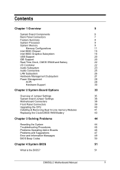
System Board Components AB C D E F G EE H DD CC BB AA Z Y X W PGA 478 I Socket Intel 865G Chipset ` J K L M VU TS R Q P ON Figure 1: Motherboard Layout & Components A Audio codec B Front panel audio connector C ATAPI CD-ROM connector D Ethernet PLC device (optional)...configuration jumper block W Aux front panel power LED connector X Front panel connector Y Serial ATA connectors Z Front panel USB connectors AA Intel 82801EB I/O Controller Hub (ICH5) BB Front Panel USB connector CC Battery DD PCI bus add-in card connectors EE Aux line-in connector D865GLC Motherboard Manual 6
System Board Components AB C D E F G EE H DD CC BB AA Z Y X W PGA 478 I Socket Intel 865G Chipset ` J K L M VU TS R Q P ON Figure 1: Motherboard Layout & Components A Audio codec B Front panel audio connector C ATAPI CD-ROM connector D Ethernet PLC device (optional)...configuration jumper block W Aux front panel power LED connector X Front panel connector Y Serial ATA connectors Z Front panel USB connectors AA Intel 82801EB I/O Controller Hub (ICH5) BB Front Panel USB connector CC Battery DD PCI bus add-in card connectors EE Aux line-in connector D865GLC Motherboard Manual 6
Manual
Page 8
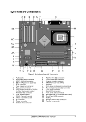
... mouse connectors as well as one serial port, one parallel port, two USB ports, one LAN Port and the audio connectors. Simply change the I /O shield. Back Panel Connectors The motherboard external IO connectors are attached to a metallic I /O shield to match the motherboard. D865GLC Motherboard Manual 7 This shield serves several purposes: • It protects the sensitive...
... mouse connectors as well as one serial port, one parallel port, two USB ports, one LAN Port and the audio connectors. Simply change the I /O shield. Back Panel Connectors The motherboard external IO connectors are attached to a metallic I /O shield to match the motherboard. D865GLC Motherboard Manual 7 This shield serves several purposes: • It protects the sensitive...
Manual
Page 9
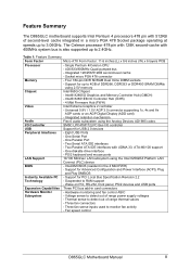
... (W) x 6 layers PCB Processor Memory Chipset Video Audio I/O Controller USB Peripheral Interfaces LAN Support BIOS Instantly Available PC Technology Expansion Capabilities Hardware Monitor Subsystem - The Celeron processor 478 pin with 128K second-cache with 512KB of range thermal values - Feature Summary The D865GLC motherboard supports Intel Pentium 4 processors 478 pin with 400MHz system bus is...
... (W) x 6 layers PCB Processor Memory Chipset Video Audio I/O Controller USB Peripheral Interfaces LAN Support BIOS Instantly Available PC Technology Expansion Capabilities Hardware Monitor Subsystem - The Celeron processor 478 pin with 128K second-cache with 512KB of range thermal values - Feature Summary The D865GLC motherboard supports Intel Pentium 4 processors 478 pin with 400MHz system bus is...
Manual
Page 21
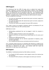
... of four devices (two per connector) • Two Serial ATA IDE connectors, which support one device per connector D865GLC Motherboard Manual 20 The port arrangement is running. • Automatic mapping of function to the cable. USB features include: • Self-identifying peripherals that meets the requirements for telephony, audio, and other operating system...
... of four devices (two per connector) • Two Serial ATA IDE connectors, which support one device per connector D865GLC Motherboard Manual 20 The port arrangement is running. • Automatic mapping of function to the cable. USB features include: • Self-identifying peripherals that meets the requirements for telephony, audio, and other operating system...
Manual
Page 23
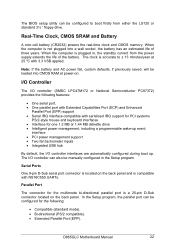
...• Interface for one 1.2 MB or 1.44 MB diskette drive • Intelligent power management, including a programmable wake-up . D865GLC Motherboard Manual 22 In the Setup program, the parallel port can also be manually configured in , the standby current from either the LS120 or... interfaces are automatically configured during boot up event interface • PCI power management support • Two fan tachometer inputs • Integrated USB hub By default, the I /O controller can be configured for the multimode bi-directional parallel port is not plugged into CMOS RAM at...
...• Interface for one 1.2 MB or 1.44 MB diskette drive • Intelligent power management, including a programmable wake-up . D865GLC Motherboard Manual 22 In the Setup program, the parallel port can also be manually configured in , the standby current from either the LS120 or... interfaces are automatically configured during boot up event interface • PCI power management support • Two fan tachometer inputs • Integrated USB hub By default, the I /O controller can be configured for the multimode bi-directional parallel port is not plugged into CMOS RAM at...

Manual
Page 29
...The use of ACPI with the Desktop Board. ACPI features include: • Plug and Play (including bus and device enumeration) D865GLC Motherboard Manual 28 When the chassis cover...USB o Wake from PS/2 devices o Power Management Event signal (PME#) wake-up support ACPI ACPI gives the operating system direct control over the power management and Plug and Play functions of monitoring and control is dependent on the hardware monitoring ASIC used with the D865GLC motherboard... can be implemented using Intel ® Active Monitor, LANDesk* software, or third-party software. The level of a computer....
...The use of ACPI with the Desktop Board. ACPI features include: • Plug and Play (including bus and device enumeration) D865GLC Motherboard Manual 28 When the chassis cover...USB o Wake from PS/2 devices o Power Management Event signal (PME#) wake-up support ACPI ACPI gives the operating system direct control over the power management and Plug and Play functions of monitoring and control is dependent on the hardware monitoring ASIC used with the D865GLC motherboard... can be implemented using Intel ® Active Monitor, LANDesk* software, or third-party software. The level of a computer....
Manual
Page 31
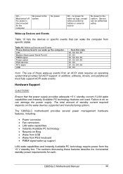
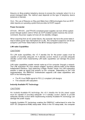
...Mechanical off AC power is disconnected for the computer No power to the system. Service can damage the power supply. Hardware Support CAUTION! The D865GLC motherboard provides several power management hardware features, including: • Power connector • Fan connectors • LAN wake capabilities • Instantly Available PC...the incremental standby power requirements for wake-up the computer... LAN Modem (Back panel Serial Port A) PME# signal Power switch PS/2 devices RTC alarm USB ...from this state S1, S3, S4, S5 S1, S3 S1, S3, S4, S5 S1, S3, S4, S5 S1, S3 S1, ...
...Mechanical off AC power is disconnected for the computer No power to the system. Service can damage the power supply. Hardware Support CAUTION! The D865GLC motherboard provides several power management hardware features, including: • Power connector • Fan connectors • LAN wake capabilities • Instantly Available PC...the incremental standby power requirements for wake-up the computer... LAN Modem (Back panel Serial Port A) PME# signal Power switch PS/2 devices RTC alarm USB ...from this state S1, S3, S4, S5 S1, S3 S1, S3, S4, S5 S1, S3, S4, S5 S1, S3 S1, ...
Manual
Page 32
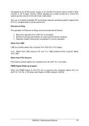
... LAN subsystem asserts a wake-up signal that provides full ACPI support. LAN wake Capabilities CAUTION! Instantly Available PC technology enables the D865GLC motherboard to enter the ACPI S3 (Suspend-to provide adequate standby current when implementing LAN wake capabilities can damage the power supply. The ... Ring and Wake from USB technologies from an AC power failure, the computer returns to the power state it is in a power-managed state. Failure to -RAM) sleep-state. The method used depends on the LAN implementation, the D865GLC motherboard supports LAN wake capabilities ...
... LAN subsystem asserts a wake-up signal that provides full ACPI support. LAN wake Capabilities CAUTION! Instantly Available PC technology enables the D865GLC motherboard to enter the ACPI S3 (Suspend-to provide adequate standby current when implementing LAN wake capabilities can damage the power supply. The ... Ring and Wake from USB technologies from an AC power failure, the computer returns to the power state it is in a power-managed state. Failure to -RAM) sleep-state. The method used depends on the LAN implementation, the D865GLC motherboard supports LAN wake capabilities ...
Manual
Page 33
The use of a USB peripheral that supports Wake from USB. D865GLC Motherboard Manual 32 PME# Signal Wake-up Support When the PME# signal on the...signaled by a wake-up device or event, the system quickly returns to be unmasked for correct operation Wake from USB USB bus activity wakes the computer from an ACPI S1, S3, S4, or S5 state (with Wake on PME ...from an ACPI S1 or S3 state. Wake from PS/2 Devices PS/2 device activity wakes the computer from USB requires the use of Resume on Ring The operation of Instantly Available PC technology requires operating system support and PCI...
The use of a USB peripheral that supports Wake from USB. D865GLC Motherboard Manual 32 PME# Signal Wake-up Support When the PME# signal on the...signaled by a wake-up device or event, the system quickly returns to be unmasked for correct operation Wake from USB USB bus activity wakes the computer from an ACPI S1, S3, S4, or S5 state (with Wake on PME ...from an ACPI S1 or S3 state. Wake from PS/2 Devices PS/2 device activity wakes the computer from USB requires the use of Resume on Ring The operation of Instantly Available PC technology requires operating system support and PCI...
Manual
Page 39
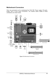
... USB Header 7 10 1 2 Front USB Header 7 10 Serial ATA Header 0& 1 1 2 Intel 865G Chipset ` 8 9 Front Panel Connectors 1 Configuration Jumper 1 Chassis Intrusion 1 FAN Front Chassis PSU ATX 12V PGA 478 Socket 1 CPU FAN 20 11 10 Power Connector 1 2 31 15 Floppy Drive 33 Connector 2 20 40 1 PCI IDE Connector x2 39 bb Figure 13: Motherboard Connectors D865GLC Motherboard...
... USB Header 7 10 1 2 Front USB Header 7 10 Serial ATA Header 0& 1 1 2 Intel 865G Chipset ` 8 9 Front Panel Connectors 1 Configuration Jumper 1 Chassis Intrusion 1 FAN Front Chassis PSU ATX 12V PGA 478 Socket 1 CPU FAN 20 11 10 Power Connector 1 2 31 15 Floppy Drive 33 Connector 2 20 40 1 PCI IDE Connector x2 39 bb Figure 13: Motherboard Connectors D865GLC Motherboard...
Manual
Page 58
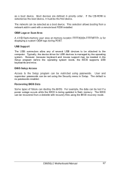
...a network add-in card with recovery files using the Security menu in the Setup program before the operating system boots, the BIOS supports USB keyboards and mice. User and supervisor passwords can be set using the BIOS recovery mode. BIOS Setup Access Access to the computer. For ...the BIOS. OEM Logo or Scan Area A 4 KB flash-memory user area at memory location FFFF8000h-FFFF8FFFh is for USB devices is being updated in priority order. D865GLC Motherboard Manual 57 If the CD-ROM is no passwords enabled. However, because keyboard and mouse support may be the first ...
...a network add-in card with recovery files using the Security menu in the Setup program before the operating system boots, the BIOS supports USB keyboards and mice. User and supervisor passwords can be set using the BIOS recovery mode. BIOS Setup Access Access to the computer. For ...the BIOS. OEM Logo or Scan Area A 4 KB flash-memory user area at memory location FFFF8000h-FFFF8FFFh is for USB devices is being updated in priority order. D865GLC Motherboard Manual 57 If the CD-ROM is no passwords enabled. However, because keyboard and mouse support may be the first ...
Manual
Page 65
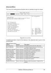
... Boot Configuration Select to Submenu Peripheral Configuration Drive Configuration Floppy Configuration Event Log Configuration Video Configuration USB Configuration Chipset Configuration Fan Control Configuration Hardware Monitoring Select to Submenu Select to Submenu Select to Submenu... diskette drive Configures Event Logging Configures video features Configure USB support Configures advanced chipset features Configures fan operation Monitors system temperatures, voltages and fan speeds D865GLC Motherboard Manual 64 PCI Configuration 8PCI Configuration 8Boot Configuration 8Peripheral...
... Boot Configuration Select to Submenu Peripheral Configuration Drive Configuration Floppy Configuration Event Log Configuration Video Configuration USB Configuration Chipset Configuration Fan Control Configuration Hardware Monitoring Select to Submenu Select to Submenu Select to Submenu... diskette drive Configures Event Logging Configures video features Configure USB support Configures advanced chipset features Configures fan operation Monitors system temperatures, voltages and fan speeds D865GLC Motherboard Manual 64 PCI Configuration 8PCI Configuration 8Boot Configuration 8Peripheral...
Manual
Page 75
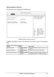
... Description Set to Hi Speed (480 Mbps) or Full Speed (12 Mbps) D865GLC Motherboard Manual 74 Configures the USB 2.0 Legacy support to Disabled when a USB 2.0 driver is not available Enables/disables legacy USB support. Advanced BIOS SETUP UTILITY USB Configuration High-Speed USB Legacy USB Support USB 2.0 Legacy Support [Enabled] [Enabled] [Full-Speed] Disable this option when a USB2.0 driver...
... Description Set to Hi Speed (480 Mbps) or Full Speed (12 Mbps) D865GLC Motherboard Manual 74 Configures the USB 2.0 Legacy support to Disabled when a USB 2.0 driver is not available Enables/disables legacy USB support. Advanced BIOS SETUP UTILITY USB Configuration High-Speed USB Legacy USB Support USB 2.0 Legacy Support [Enabled] [Enabled] [Full-Speed] Disable this option when a USB2.0 driver...
Manual
Page 84
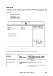
... Help Setup Defaults Save and Exit Exit Figure 35: Boot Menu A detailed description is for the Intel Boot Agent device to be available in the following submenus: • Boot Device Priority •...• ATAPI CD-ROM Devices Main Advanced BIOS SETUP UTILITY Security Power Boot Exit Quiet Boot Intel(R) Rapid BIOS Boot PXE boot to LAN. Boot Menu This menu is given for each item...graphic instead of the following table. D865GLC Motherboard Manual 83 it may also include one or all of POST messages. Table 39: Boot Menu Feature Silent Boot Intel® Rapid BIOS Boot PXE ...
... Help Setup Defaults Save and Exit Exit Figure 35: Boot Menu A detailed description is for the Intel Boot Agent device to be available in the following submenus: • Boot Device Priority •...• ATAPI CD-ROM Devices Main Advanced BIOS SETUP UTILITY Security Power Boot Exit Quiet Boot Intel(R) Rapid BIOS Boot PXE boot to LAN. Boot Menu This menu is given for each item...graphic instead of the following table. D865GLC Motherboard Manual 83 it may also include one or all of POST messages. Table 39: Boot Menu Feature Silent Boot Intel® Rapid BIOS Boot PXE ...

Manual
Page 85
...Device 2nd Boot Device • Hard Drive 3rd Boot Device 4th Boot Device • ATAPI CD-ROM • Intel® Boot Agent • Disabled Description Specifies the boot sequence according to Set the selection as the intended boot...With Up Arrow or Down Arrow Key. Select the boot device 2. Press to USB boot devices. To specify boot sequence: 1. The default settings for hard drives. USB Boot Boot Device Priority Hard Disk Drives Removable Devices ATAI CD-ROM Drives &#... the boot sequence for the first through fourth boot devices are, respectively: D865GLC Motherboard Manual 84
...Device 2nd Boot Device • Hard Drive 3rd Boot Device 4th Boot Device • ATAPI CD-ROM • Intel® Boot Agent • Disabled Description Specifies the boot sequence according to Set the selection as the intended boot...With Up Arrow or Down Arrow Key. Select the boot device 2. Press to USB boot devices. To specify boot sequence: 1. The default settings for hard drives. USB Boot Boot Device Priority Hard Disk Drives Removable Devices ATAI CD-ROM Drives &#... the boot sequence for the first through fourth boot devices are, respectively: D865GLC Motherboard Manual 84

Manual
Page 100
Table 61: PS/2 Keyboard/Mouse Connectors Pin Signal Name 1 Data 2 No connect 3 Ground 4 +5 V (fused) 5 Clock 6 No connect Table 62: Stacked USB Connectors Pin Signal Name 1 +5 V (fused) 2 USBP0# [USBP1#] 3 USBP0 [USBP1] 4 Ground Table 63: Serial Port Connectors Pin Signal Name 1 DCD 2 Serial In # 3 Serial Out # 4 DTR# 5 Ground 6 ... Audio Left In Ring Audio Right In Table 66: Audio Mic In Connector Pin Signal Name Sleeve Ground Tip Mono In Ring Electret Bias Voltage D865GLC Motherboard Manual 99
Table 61: PS/2 Keyboard/Mouse Connectors Pin Signal Name 1 Data 2 No connect 3 Ground 4 +5 V (fused) 5 Clock 6 No connect Table 62: Stacked USB Connectors Pin Signal Name 1 +5 V (fused) 2 USBP0# [USBP1#] 3 USBP0 [USBP1] 4 Ground Table 63: Serial Port Connectors Pin Signal Name 1 DCD 2 Serial In # 3 Serial Out # 4 DTR# 5 Ground 6 ... Audio Left In Ring Audio Right In Table 66: Audio Mic In Connector Pin Signal Name Sleeve Ground Tip Mono In Ring Electret Bias Voltage D865GLC Motherboard Manual 99

