Manual
Page 4
... Subsystem Audio Connectors LAN Subsystem Hardware Management Subsystem Power Management ACPI Hardware Support Chapter 2 System Board Options Overview of Jumper Settings System Board Jumper Settings Motherboard Connectors Front Panel Connectors Upgrading the CPU Installing & Removing Dual In-Line memory Modules Replacing the Clock/CMOS RAM Battery Chapter 3 Solving Problems Resetting the System Troubleshooting Procedures Problems Operating Add-in Boards Problems and Suggestions Error and Information Messages BIOS Beep Codes Chapter 4 System BIOS What is the BIOS? D865GLC Motherboard Manual...
... Subsystem Audio Connectors LAN Subsystem Hardware Management Subsystem Power Management ACPI Hardware Support Chapter 2 System Board Options Overview of Jumper Settings System Board Jumper Settings Motherboard Connectors Front Panel Connectors Upgrading the CPU Installing & Removing Dual In-Line memory Modules Replacing the Clock/CMOS RAM Battery Chapter 3 Solving Problems Resetting the System Troubleshooting Procedures Problems Operating Add-in Boards Problems and Suggestions Error and Information Messages BIOS Beep Codes Chapter 4 System BIOS What is the BIOS? D865GLC Motherboard Manual...
Manual
Page 7
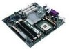
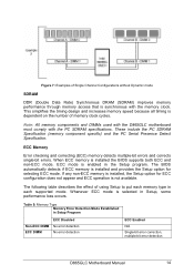
... fan connector K Intel 82865G GMCH L DIMM Channel A socket M DIMM Channel B socket N I/O controller O Power connector P Diskette drive connector Q Parallel ATA IDE connectors R Front chassis fan connector S Chassis intrusion connector T 4 Mbit Firmware Hub (FWH) U Speaker V BIOS Setup configuration jumper block W Aux front panel power LED connector X Front panel connector Y Serial ATA connectors Z Front panel USB connectors AA Intel 82801EB I/O Controller Hub (ICH5) BB Front Panel USB connector CC Battery DD PCI bus add-in card connectors EE Aux line-in connector D865GLC Motherboard Manual...
... fan connector K Intel 82865G GMCH L DIMM Channel A socket M DIMM Channel B socket N I/O controller O Power connector P Diskette drive connector Q Parallel ATA IDE connectors R Front chassis fan connector S Chassis intrusion connector T 4 Mbit Firmware Hub (FWH) U Speaker V BIOS Setup configuration jumper block W Aux front panel power LED connector X Front panel connector Y Serial ATA connectors Z Front panel USB connectors AA Intel 82801EB I/O Controller Hub (ICH5) BB Front Panel USB connector CC Battery DD PCI bus add-in card connectors EE Aux line-in connector D865GLC Motherboard Manual...
Manual
Page 9
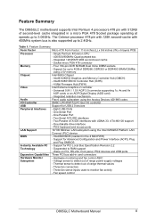
... Graphics 2 controller - Support for Advanced Configuration and Power Interface (ACPI), Plug and Play SMBIOS - One Serial Port - Intel/AMI BIOS (resident in card connectors - Support for USB 2.0 devices - Feature Summary The D865GLC motherboard supports Intel Pentium 4 processors 478 pin with 512KB of second-level cache integrated in a micro PGA 478 Socket package operating at speeds up to monitor fan activity - Integrated 128/256/512KB second-level cache - PS/2 keyboard and mouse ports 10/100 Mbit/sec LAN subsystem using 2.5V memory Intel...
... Graphics 2 controller - Support for Advanced Configuration and Power Interface (ACPI), Plug and Play SMBIOS - One Serial Port - Intel/AMI BIOS (resident in card connectors - Support for USB 2.0 devices - Feature Summary The D865GLC motherboard supports Intel Pentium 4 processors 478 pin with 512KB of second-level cache integrated in a micro PGA 478 Socket package operating at speeds up to monitor fan activity - Integrated 128/256/512KB second-level cache - PS/2 keyboard and mouse ports 10/100 Mbit/sec LAN subsystem using 2.5V memory Intel...
Manual
Page 15
... SDRAM Specification (memory component specific) and the PC Serial Presence Detect Specification. Whenever ECC mode is installed the BIOS supports both ECC and non-ECC mode. The following table describes the effect of using Setup to put each supported mode. Table 5: Memory Type Memory Error Detection Mode Established in each memory type in Setup Program Non-ECC DIMM ECC DIMM ECC Disabled No error detection No error detection ECC Enabled N/A Single-bit error correction, multiple-bit error detection D865GLC Motherboard Manual 14 ECC mode...
... SDRAM Specification (memory component specific) and the PC Serial Presence Detect Specification. Whenever ECC mode is installed the BIOS supports both ECC and non-ECC mode. The following table describes the effect of using Setup to put each supported mode. Table 5: Memory Type Memory Error Detection Mode Established in each memory type in Setup Program Non-ECC DIMM ECC DIMM ECC Disabled No error detection No error detection ECC Enabled N/A Single-bit error correction, multiple-bit error detection D865GLC Motherboard Manual 14 ECC mode...
Manual
Page 21
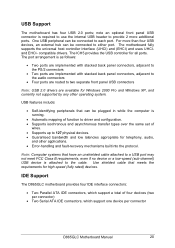
... ports are implemented with stacked back panel connectors, adjacent to the PS/2 connectors • Two ports are implemented with stacked back panel connectors, adjacent to the audio connectors • Four ports are routed to the cable. One USB peripheral can be connected to each port. compatible drivers. The ICH5 provides the USB controller for Windows 2000 Pro and Windows XP, and currently not supported by any other applications. • Error-handling and fault-recovery...
... ports are implemented with stacked back panel connectors, adjacent to the PS/2 connectors • Two ports are implemented with stacked back panel connectors, adjacent to the audio connectors • Four ports are routed to the cable. One USB peripheral can be connected to each port. compatible drivers. The ICH5 provides the USB controller for Windows 2000 Pro and Windows XP, and currently not supported by any other applications. • Error-handling and fault-recovery...
Manual
Page 37
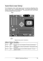
... menu is required. The following figure shows the location of front panel audio. J9A2 Intel 865G Chipset ` PGA 478 Socket J9J4 Figure 12: Single-Jumper Configurations Table 11: Configuration Jumper Settings Function Jumper Configuration J9J4 Normal 1-2 The BIOS uses current configuration information and passwords for booting. A recovery diskette is displayed. D865GLC Motherboard Manual 36 System Board Jumper Settings The Configuration Jumper (J9J4) allows the user to enter the configuration mode, and to recover the BIOS configuration. Configure 2-3 After the POST runs, Setup...
... menu is required. The following figure shows the location of front panel audio. J9A2 Intel 865G Chipset ` PGA 478 Socket J9J4 Figure 12: Single-Jumper Configurations Table 11: Configuration Jumper Settings Function Jumper Configuration J9J4 Normal 1-2 The BIOS uses current configuration information and passwords for booting. A recovery diskette is displayed. D865GLC Motherboard Manual 36 System Board Jumper Settings The Configuration Jumper (J9J4) allows the user to enter the configuration mode, and to recover the BIOS configuration. Configure 2-3 After the POST runs, Setup...
Manual
Page 49
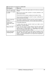
... Hard drive light does not go on when drive is in use or is tested by POST Make sure the power and signal cables for remote hard disk drive activity. Check the drive manufacturer's manual for proper configuration for the drive are properly installed. Provide this information to make changes, check the switch that the drive is properly configured and enabled in Setup. D865GLC Motherboard Manual 48 Setup, can't enter If you might need to clear CMOS RAM to the default...
... Hard drive light does not go on when drive is in use or is tested by POST Make sure the power and signal cables for remote hard disk drive activity. Check the drive manufacturer's manual for proper configuration for the drive are properly installed. Provide this information to make changes, check the switch that the drive is properly configured and enabled in Setup. D865GLC Motherboard Manual 48 Setup, can't enter If you might need to clear CMOS RAM to the default...
Manual
Page 50
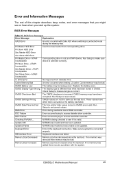
... controller. ATAPI Incompatible A: Drive Error No response from corresponding drive. Replace the battery soon. Run Setup to access hard disk controller. These values have been corrupted. HDC Failure Error occurred trying to reset values. Update OK! NVRAM was removed then memory may be bad. Pri Slave HDD Error Sec Master HDD Error Sec Slave HDD Error Pri Master Drive - Run Setup to make sure type is selected correctly. CMOS Battery Low The battery may be a problem with Gate A20 when switching...
... controller. ATAPI Incompatible A: Drive Error No response from corresponding drive. Replace the battery soon. Run Setup to access hard disk controller. These values have been corrupted. HDC Failure Error occurred trying to reset values. Update OK! NVRAM was removed then memory may be bad. Pri Slave HDD Error Sec Master HDD Error Sec Slave HDD Error Pri Master Drive - Run Setup to make sure type is selected correctly. CMOS Battery Low The battery may be a problem with Gate A20 when switching...
Manual
Page 51
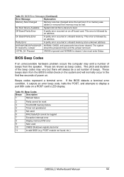
... error condition, it outputs an error beep code, halts the POST, and attempts to boot. Off Board Parity Error A parity error occurred on a POST card's LED display. Pressed CMOS is ignored and NVRAM is cleared. These beeps stem from the speaker. Table 16: Beep Codes Beeps Description 1 Refresh failure 2 Parity cannot be reset 3 First 64 KB memory failure 4 Timer not operational 5 Not used 6 8042 GateA20 cannot be powered down and the jumper removed. POST module not found, etc.) D865GLC Motherboard Manual 50...
... error condition, it outputs an error beep code, halts the POST, and attempts to boot. Off Board Parity Error A parity error occurred on a POST card's LED display. Pressed CMOS is ignored and NVRAM is cleared. These beeps stem from the speaker. Table 16: Beep Codes Beeps Description 1 Refresh failure 2 Parity cannot be reset 3 First 64 KB memory failure 4 Timer not operational 5 Not used 6 8042 GateA20 cannot be powered down and the jumper removed. POST module not found, etc.) D865GLC Motherboard Manual 50...
Manual
Page 54
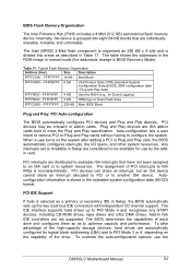
Internally, the device is selected as described in Setup, the BIOS automatically sets up to PIO Mode 4 and recognises any ATAPI devices, including CD-ROM drives, tape drives and Ultra DMA drives. Table 17: Typical Flash Memory Organisation Address (Hex) Size Description FFFFC000 - PCI devices may be available for use the D865GLC Motherboard Manual 53 Any interrupts set to meet the Plug and Play specification. The assignment of the high-capacity storage devices, hard drives are not supported. The IDE interface...
Internally, the device is selected as described in Setup, the BIOS automatically sets up to PIO Mode 4 and recognises any ATAPI devices, including CD-ROM drives, tape drives and Ultra DMA drives. Table 17: Typical Flash Memory Organisation Address (Hex) Size Description FFFFC000 - PCI devices may be available for use the D865GLC Motherboard Manual 53 Any interrupts set to meet the Plug and Play specification. The assignment of the high-capacity storage devices, hard drives are not supported. The IDE interface...
Manual
Page 56
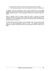
... Setup. • Suspend/resume switch connected to the front panel sleep connector. • From the operating system, such as incoming faxes or network messages. Power-management mode can be enabled or disabled in Windows 95. D865GLC Motherboard Manual 55 Any keyboard or mouse activity brings the system out of standby mode and immediately restores power to or turning off VESA DPMS-compliant monitors. The BIOS enables APM by using SMM capabilities, spinning down hard drives...
... Setup. • Suspend/resume switch connected to the front panel sleep connector. • From the operating system, such as incoming faxes or network messages. Power-management mode can be enabled or disabled in Windows 95. D865GLC Motherboard Manual 55 Any keyboard or mouse activity brings the system out of standby mode and immediately restores power to or turning off VESA DPMS-compliant monitors. The BIOS enables APM by using SMM capabilities, spinning down hard drives...

Manual
Page 57
... individual devices, add-in boards, video displays, and hard disk drives. • Methods for Off Less than 4 seconds On Less than 4 seconds On More than 4 seconds Sleep Less than 5-watt system operation in the Suspended to be supported in the BIOS. • Power management control of low-power state based on ACPI. Booting from a floppy drive, hard drive, CD-ROM, or the network. The default setting is programmed into the BIOS using the flash memory update utility. The default language...
... individual devices, add-in boards, video displays, and hard disk drives. • Methods for Off Less than 4 seconds On Less than 4 seconds On More than 4 seconds Sleep Less than 5-watt system operation in the Suspended to be supported in the BIOS. • Power management control of low-power state based on ACPI. Booting from a floppy drive, hard drive, CD-ROM, or the network. The default setting is programmed into the BIOS using the flash memory update utility. The default language...
Manual
Page 65
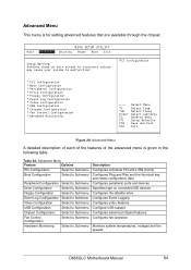
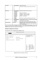
... SETUP UTILITY Security Power Boot Exit Setup Warning Setting items on this screen to incorrect values may cause your system to Submenu Description Configures individual PCI slot's IRQ priority Configures Plug and Play and the Numlock key, and resets configuration data Configures peripheral ports and devices Specifies type on connected IDE devices Configures the diskette drive Configures Event Logging Configures video features Configure USB support Configures advanced chipset features Configures fan operation Monitors system temperatures, voltages and fan speeds D865GLC Motherboard Manual...
... SETUP UTILITY Security Power Boot Exit Setup Warning Setting items on this screen to incorrect values may cause your system to Submenu Description Configures individual PCI slot's IRQ priority Configures Plug and Play and the Numlock key, and resets configuration data Configures peripheral ports and devices Specifies type on connected IDE devices Configures the diskette drive Configures Event Logging Configures video features Configure USB support Configures advanced chipset features Configures fan operation Monitors system temperatures, voltages and fan speeds D865GLC Motherboard Manual...
Manual
Page 69
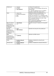
... port Specifies the DMA channel Enables or disables the onboard audio subsystem Enables or disables the onboard LAN device D865GLC Motherboard Manual 68 Not available if the parallel port is Enhanced Capabilities Port mode, a high-speed bi-directional mode Specifies the base I /O address • 378 (default) (This feature is • 278 present only when Parallel Port is set to Enabled) Interrupt • IRQ5 (This feature is • IRQ7 (default) present only when Parallel Port is set to Enabled...
... port Specifies the DMA channel Enables or disables the onboard audio subsystem Enables or disables the onboard LAN device D865GLC Motherboard Manual 68 Not available if the parallel port is Enhanced Capabilities Port mode, a high-speed bi-directional mode Specifies the base I /O address • 378 (default) (This feature is • 278 present only when Parallel Port is set to Enabled) Interrupt • IRQ5 (This feature is • IRQ7 (default) present only when Parallel Port is set to Enabled...
Manual
Page 70
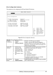
... • SATA P0/P1, PATA Pri PCI IDE Bus Master • Disabled • Enabled (default) Disabled = All IDE resources disabled Legacy = Up to legacy Enables/disables the use of DMA for hard drive BIOS INT13 reads and writes D865GLC Motherboard Manual 69 Drive Configuration Submenu This submenu is set to two IDE channels enabled for operating systems that require legacy IDE operation Enhanced = All Serial ATA (SATA) and Parallel ATA (PATA) resources enabled Configures PATA and SATA resources for operating systems that require legacy IDE operation.
... • SATA P0/P1, PATA Pri PCI IDE Bus Master • Disabled • Enabled (default) Disabled = All IDE resources disabled Legacy = Up to legacy Enables/disables the use of DMA for hard drive BIOS INT13 reads and writes D865GLC Motherboard Manual 69 Drive Configuration Submenu This submenu is set to two IDE channels enabled for operating systems that require legacy IDE operation Enhanced = All Serial ATA (SATA) and Parallel ATA (PATA) resources enabled Configures PATA and SATA resources for operating systems that require legacy IDE operation.
Manual
Page 71
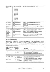
.../Large mode Block Mode No Option • Disabled • Auto (default) • Disabled • Auto (default) Description Displays the type of drive installed Specifies the IDE configuration mode for IDE devices User allows capabilities to be changed Auto fills-in capabilities from ATA/ATAPI devices Displays the drive capacity Displays whether automatic translation mode is enabled from the hard disk (This item is read only unless Type is set to User) Displays whether automatic multiple sector data transfers are six SATA/PATA submenus: SATA Port-0, SATA Port-1, PATA...
.../Large mode Block Mode No Option • Disabled • Auto (default) • Disabled • Auto (default) Description Displays the type of drive installed Specifies the IDE configuration mode for IDE devices User allows capabilities to be changed Auto fills-in capabilities from ATA/ATAPI devices Displays the drive capacity Displays whether automatic translation mode is enabled from the hard disk (This item is read only unless Type is set to User) Displays whether automatic multiple sector data transfers are six SATA/PATA submenus: SATA Port-0, SATA Port-1, PATA...
Manual
Page 72
...-120 drive is set to User) Cable Detected No Option Displays the type of cable connected to the Parallel ARA IDE interface: 40-conductor or 80-conductor (for configuring the diskette drives. Advanced BIOS SETUP UTILITY Floppy Configuration Diskette Controller Floppy A Diskette Write Protect [Enabled] [1.44/1.25 MB 3½"] [Disable] Configures the integrated diskette controller ←→ ↑↓ Tab Enter F1 F9 F10 ESC Select Menu Select Item Select Field Select sub-menu General Help Setup Defaults...
...-120 drive is set to User) Cable Detected No Option Displays the type of cable connected to the Parallel ARA IDE interface: 40-conductor or 80-conductor (for configuring the diskette drives. Advanced BIOS SETUP UTILITY Floppy Configuration Diskette Controller Floppy A Diskette Write Protect [Enabled] [1.44/1.25 MB 3½"] [Disable] Configures the integrated diskette controller ←→ ↑↓ Tab Enter F1 F9 F10 ESC Select Menu Select Item Select Field Select sub-menu General Help Setup Defaults...
Manual
Page 75
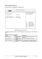
...USB Configuration Submenu Feature Options High-Speed USB • Enabled (default) • Disabled Legacy USB Support USB 2.0 Legacy Support • Enabled (default) • Disabled • FullSpeed (default) • Hi Speed Description Set to Hi Speed (480 Mbps) or Full Speed (12 Mbps) D865GLC Motherboard Manual 74 Advanced BIOS SETUP UTILITY USB Configuration High-Speed USB Legacy USB Support USB 2.0 Legacy Support [Enabled] [Enabled] [Full-Speed] Disable this option when a USB2.0 driver is not available ←→ ↑↓ Tab Enter F1 F9 F10 ESC Select Menu...
...USB Configuration Submenu Feature Options High-Speed USB • Enabled (default) • Disabled Legacy USB Support USB 2.0 Legacy Support • Enabled (default) • Disabled • FullSpeed (default) • Hi Speed Description Set to Hi Speed (480 Mbps) or Full Speed (12 Mbps) D865GLC Motherboard Manual 74 Advanced BIOS SETUP UTILITY USB Configuration High-Speed USB Legacy USB Support USB 2.0 Legacy Support [Enabled] [Enabled] [Full-Speed] Disable this option when a USB2.0 driver is not available ←→ ↑↓ Tab Enter F1 F9 F10 ESC Select Menu...
Manual
Page 77
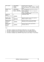
Manual - User Defined = Allows manual override of clock cycles between addressing a row and addressing a column. D865GLC Motherboard Manual 76 CPC Override SDRAM Timing Control (Note 1) • Auto (default) • Enabled • Disabled • Auto (default) • Manual - Aggressive = Selects most aggressive user-defined timings. This option is displayed only if the installed processor has an 800 MHz system bus. 4. Note: 1. This option is displayed only if the installed processor has a 533 MHz system bus. 3. Corresponds to tRAS...
Manual - User Defined = Allows manual override of clock cycles between addressing a row and addressing a column. D865GLC Motherboard Manual 76 CPC Override SDRAM Timing Control (Note 1) • Auto (default) • Enabled • Disabled • Auto (default) • Manual - Aggressive = Selects most aggressive user-defined timings. This option is displayed only if the installed processor has an 800 MHz system bus. 4. Note: 1. This option is displayed only if the installed processor has a 533 MHz system bus. 3. Corresponds to tRAS...
Manual
Page 84
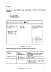
... Boot Device Priority • Hard Disk Drives • Removable Devices • ATAPI CD-ROM Devices Main Advanced BIOS SETUP UTILITY Security Power Boot Exit Quiet Boot Intel(R) Rapid BIOS Boot PXE boot to LAN Options • Disabled • Enabled (default) • Disabled • Enabled (default) • Disabled (default) • Enabled Description Disabled displays normal POST messages. Disables/enables PXE boot to boot without running certain POST tests. Boot Menu This menu is given for each item in the Boot Device menu. D865GLC Motherboard Manual 83 Enabled, displays...
... Boot Device Priority • Hard Disk Drives • Removable Devices • ATAPI CD-ROM Devices Main Advanced BIOS SETUP UTILITY Security Power Boot Exit Quiet Boot Intel(R) Rapid BIOS Boot PXE boot to LAN Options • Disabled • Enabled (default) • Disabled • Enabled (default) • Disabled (default) • Enabled Description Disabled displays normal POST messages. Disables/enables PXE boot to boot without running certain POST tests. Boot Menu This menu is given for each item in the Boot Device menu. D865GLC Motherboard Manual 83 Enabled, displays...


