Manual
Page 4
... System Processor System Memory Memory Configurations Intel 865G Chipset Intel 865G Graphics Subsystem USB Support IDE Support Real-Time Clock, CMOS SRAM and Battery I/O Controller Audio Subsystem Audio Connectors LAN Subsystem Hardware Management Subsystem Power Management ACPI Hardware Support Chapter 2 System Board Options Overview of Jumper Settings System Board Jumper Settings Motherboard Connectors Front Panel Connectors Upgrading...
... System Processor System Memory Memory Configurations Intel 865G Chipset Intel 865G Graphics Subsystem USB Support IDE Support Real-Time Clock, CMOS SRAM and Battery I/O Controller Audio Subsystem Audio Connectors LAN Subsystem Hardware Management Subsystem Power Management ACPI Hardware Support Chapter 2 System Board Options Overview of Jumper Settings System Board Jumper Settings Motherboard Connectors Front Panel Connectors Upgrading...
Manual
Page 7
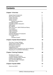
System Board Components AB C D E F G EE H DD CC BB AA Z Y X W PGA 478 I Socket Intel 865G Chipset ` J K L M VU TS R Q P ON Figure 1: Motherboard Layout & Components A Audio codec B Front panel audio connector C ATAPI CD-ROM connector D Ethernet PLC device (optional) E... configuration jumper block W Aux front panel power LED connector X Front panel connector Y Serial ATA connectors Z Front panel USB connectors AA Intel 82801EB I/O Controller Hub (ICH5) BB Front Panel USB connector CC Battery DD PCI bus add-in card connectors EE Aux line-in connector D865GLC Motherboard Manual...
System Board Components AB C D E F G EE H DD CC BB AA Z Y X W PGA 478 I Socket Intel 865G Chipset ` J K L M VU TS R Q P ON Figure 1: Motherboard Layout & Components A Audio codec B Front panel audio connector C ATAPI CD-ROM connector D Ethernet PLC device (optional) E... configuration jumper block W Aux front panel power LED connector X Front panel connector Y Serial ATA connectors Z Front panel USB connectors AA Intel 82801EB I/O Controller Hub (ICH5) BB Front Panel USB connector CC Battery DD PCI bus add-in card connectors EE Aux line-in connector D865GLC Motherboard Manual...

Manual
Page 36
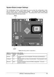
... CMOS becoming corrupted then jumper J9J4 can damage the pins. All Pentium 4 CPUs are automatically detected and the Speed is switch on the motherboard is to use a small pair of Jumper Settings The D865GLC motherboard contains the latest technology to remove a jumper is for clearing all the... CMOS settings. Never remove jumpers using large pliers as this can be set from the...
... CMOS becoming corrupted then jumper J9J4 can damage the pins. All Pentium 4 CPUs are automatically detected and the Speed is switch on the motherboard is to use a small pair of Jumper Settings The D865GLC motherboard contains the latest technology to remove a jumper is for clearing all the... CMOS settings. Never remove jumpers using large pliers as this can be set from the...
Manual
Page 37
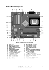
... POST runs, Setup runs automatically. D865GLC Motherboard Manual 36 A recovery diskette is displayed. The following figure shows the location of front panel audio. The audio jumper block (J9A2) allows the implementation of the header on the motherboard. Recovery None The BIOS attempts to recover from a corrupted BIOS update. J9A2 Intel 865G Chipset ` PGA 478 Socket...
... POST runs, Setup runs automatically. D865GLC Motherboard Manual 36 A recovery diskette is displayed. The following figure shows the location of front panel audio. The audio jumper block (J9A2) allows the implementation of the header on the motherboard. Recovery None The BIOS attempts to recover from a corrupted BIOS update. J9A2 Intel 865G Chipset ` PGA 478 Socket...

Manual
Page 38
...off the power and unplug the power cord from the computer before changing the jumper. See BIOS Section for front panel audio connectors on . D865GLC Motherboard Manual 37 Table 12: Front Panel Audio Jumper Settings Function Jumper Configuration J9A2 Normal 5 - 6 The audio line signals are installed. Table... LEFT_IN CAUTION! The feature for configuring the processor speed is no jumpers are routed back to the line connector. Do not move the jumper with the power on this connector when no jumper setting for configuring the processor speed or bus frequency. and 9- ...
...off the power and unplug the power cord from the computer before changing the jumper. See BIOS Section for front panel audio connectors on . D865GLC Motherboard Manual 37 Table 12: Front Panel Audio Jumper Settings Function Jumper Configuration J9A2 Normal 5 - 6 The audio line signals are installed. Table... LEFT_IN CAUTION! The feature for configuring the processor speed is no jumpers are routed back to the line connector. Do not move the jumper with the power on this connector when no jumper setting for configuring the processor speed or bus frequency. and 9- ...
Manual
Page 39
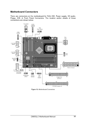
... 1 2 Front USB Header 7 10 Serial ATA Header 0& 1 1 2 Intel 865G Chipset ` 8 9 Front Panel Connectors 1 Configuration Jumper 1 Chassis Intrusion 1 FAN Front Chassis PSU ATX 12V PGA 478 Socket 1 CPU FAN 20 11 10 Power Connector 1 2 31 15 Floppy Drive 33 Connector 2 20 40 1 PCI IDE Connector x2 39 bb Figure 13: Motherboard Connectors D865GLC Motherboard Manual 38
... 1 2 Front USB Header 7 10 Serial ATA Header 0& 1 1 2 Intel 865G Chipset ` 8 9 Front Panel Connectors 1 Configuration Jumper 1 Chassis Intrusion 1 FAN Front Chassis PSU ATX 12V PGA 478 Socket 1 CPU FAN 20 11 10 Power Connector 1 2 31 15 Floppy Drive 33 Connector 2 20 40 1 PCI IDE Connector x2 39 bb Figure 13: Motherboard Connectors D865GLC Motherboard Manual 38

Manual
Page 48
... the software documentation for example, the time of the software that the brightness and contrast controls are properly installed. Check that the system board jumpers are wrong If system settings stored in and turned on. Make sure all of system settings available to re-enter, because clearing CMOS ... Try resetting the system. Check that your system hardware configuration is compatible with the copy you recorded previously. Make sure a video board is with the video mode you have your monitor is set properly. Reboot the system. D865GLC Motherboard Manual 47
... the software documentation for example, the time of the software that the brightness and contrast controls are properly installed. Check that the system board jumpers are wrong If system settings stored in and turned on. Make sure all of system settings available to re-enter, because clearing CMOS ... Try resetting the system. Check that your system hardware configuration is compatible with the copy you recorded previously. Make sure a video board is with the video mode you have your monitor is set properly. Reboot the system. D865GLC Motherboard Manual 47
Manual
Page 51
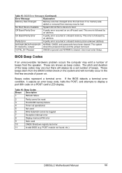
...KB memory failure 4 Timer not operational 5 Not used 6 8042 GateA20 cannot be powered down and the jumper removed. Parity Error A parity error occurred in onboard memory. The system D cleared by an address. ... beeps stem from the speaker. This error is cleared. POST module not found, etc.) D865GLC Motherboard Manual 50 If no memory was added or removed then memory may vary but there will ... display a port 80h code on the system and will always be bad. On Board Parity Error A parity error occurred in onboard memory at an unknown address. These are known...
...KB memory failure 4 Timer not operational 5 Not used 6 8042 GateA20 cannot be powered down and the jumper removed. Parity Error A parity error occurred in onboard memory. The system D cleared by an address. ... beeps stem from the speaker. This error is cleared. POST module not found, etc.) D865GLC Motherboard Manual 50 If no memory was added or removed then memory may vary but there will ... display a port 80h code on the system and will always be bad. On Board Parity Error A parity error occurred in onboard memory at an unknown address. These are known...

Manual
Page 60
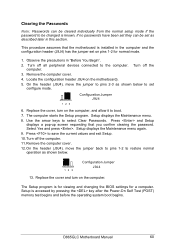
... header (Figure 12, J9J4 on pins 1-2 for normal mode. 1. D865GLC Motherboard Manual 59 Replace the cover, turn on the computer, and allow it to confirm the speed. On the header (J9J4), move the jumper to pins 2-3 as shown below to select the processor speed. Setting the...9. Use the arrow keys to set on the motherboard). 5. This procedure assumes that the motherboard is installed in the computer and the configuration header (J9J4) has the jumper set configure mode. 1 2 3 Configuration Jumper J9J4 6. On the header, move the jumper back to pins 1-2 to save the current values...
... header (Figure 12, J9J4 on pins 1-2 for normal mode. 1. D865GLC Motherboard Manual 59 Replace the cover, turn on the computer, and allow it to confirm the speed. On the header (J9J4), move the jumper to pins 2-3 as shown below to select the processor speed. Setting the...9. Use the arrow keys to set on the motherboard). 5. This procedure assumes that the motherboard is installed in the computer and the configuration header (J9J4) has the jumper set configure mode. 1 2 3 Configuration Jumper J9J4 6. On the header, move the jumper back to pins 1-2 to save the current values...
Manual
Page 61
...mode. 1 2 3 Configuration Jumper J9J4 6. The Setup program is accessed by pressing the key after the Power-On Self Test (POST) memory test begins and before the operating system boot begins. D865GLC Motherboard Manual 60 On the header (J9J4), move the jumper to pins 2-3 as shown ...below to set as shown below. 1 2 3 Configuration Jumper J9J4 13. Press and Setup displays a pop-up screen requesting that ...
...mode. 1 2 3 Configuration Jumper J9J4 6. The Setup program is accessed by pressing the key after the Power-On Self Test (POST) memory test begins and before the operating system boot begins. D865GLC Motherboard Manual 60 On the header (J9J4), move the jumper to pins 2-3 as shown ...below to set as shown below. 1 2 3 Configuration Jumper J9J4 13. Press and Setup displays a pop-up screen requesting that ...

Manual
Page 63
... sub- This menu reports processor and memory information and is for the processor frequency the menu will appear as below is displayed. D865GLC Motherboard Manual 62 Displays CPU's Stepping Signature Displays CPU's Microcode Update Revision Main Menu When in configuration mode. Setup only displays this menu... in normal mode "Jumper (J9J4) set across pins 1 and 2" the main menu will appear as below after selecting during power on boot up when the ...
... sub- This menu reports processor and memory information and is for the processor frequency the menu will appear as below is displayed. D865GLC Motherboard Manual 62 Displays CPU's Stepping Signature Displays CPU's Microcode Update Revision Main Menu When in configuration mode. Setup only displays this menu... in normal mode "Jumper (J9J4) set across pins 1 and 2" the main menu will appear as below after selecting during power on boot up when the ...

Manual
Page 92
... see the message: Press Key if you see anything on the motherboard). 4. Turn off the computer and reboot. On the header (J9J4), remove the jumper from all peripheral devices connected to the computer. Press . 7....flash the new BIOS into memory, select continue with Programming. Remove the computer cover. 3. Locate the configuration header (Jumper J9J4 on the screen during the procedure. Press . 6. Set the options in the non-erasable boot block area... the Setup program defaults. See Chapter 3 for Setup. 1 2 3 Configuration Jumper J9J4 D865GLC Motherboard Manual 91
... see the message: Press Key if you see anything on the motherboard). 4. Turn off the computer and reboot. On the header (J9J4), remove the jumper from all peripheral devices connected to the computer. Press . 7....flash the new BIOS into memory, select continue with Programming. Remove the computer cover. 3. Locate the configuration header (Jumper J9J4 on the screen during the procedure. Press . 6. Set the options in the non-erasable boot block area... the Setup program defaults. See Chapter 3 for Setup. 1 2 3 Configuration Jumper J9J4 D865GLC Motherboard Manual 91

Manual
Page 93
... cord from the computer. If recovery is successful, turn on the computer. On the header (J9J9), move the jumper back to pins 1-2 as shown below to step 1 and repeat the recovery process. 10. D865GLC Motherboard Manual 92 Listen to boot. 7. The recovery process will take a few minutes. 8. Remove the computer cover and continue...
... cord from the computer. If recovery is successful, turn on the computer. On the header (J9J9), move the jumper back to pins 1-2 as shown below to step 1 and repeat the recovery process. 10. D865GLC Motherboard Manual 92 Listen to boot. 7. The recovery process will take a few minutes. 8. Remove the computer cover and continue...


