Product Guide
Page 6
... Panel Header 43 Connecting Hardware Control and Power Cables 44 Connecting the Chassis Intrusion Cable 45 Connecting Fans ...45 Connecting Power Cables 45 Setting the BIOS Configuration Jumper Block 46 Clearing Passwords ...47 Replacing the Battery ...48 3 Updating the BIOS Updating the BIOS with the Intel® Express BIOS Update Utility 53 Updating the BIOS with the Iflash Memory Update Utility 54 Obtaining the BIOS Update File 54 Updating the BIOS...54 Recovering the BIOS 55 4 Using the BIOS Setup Program Maintenance Menu...58 Main Menu ...59 Advanced Menu ...60 PCI Configuration...
... Panel Header 43 Connecting Hardware Control and Power Cables 44 Connecting the Chassis Intrusion Cable 45 Connecting Fans ...45 Connecting Power Cables 45 Setting the BIOS Configuration Jumper Block 46 Clearing Passwords ...47 Replacing the Battery ...48 3 Updating the BIOS Updating the BIOS with the Intel® Express BIOS Update Utility 53 Updating the BIOS with the Iflash Memory Update Utility 54 Obtaining the BIOS Update File 54 Updating the BIOS...54 Recovering the BIOS 55 4 Using the BIOS Setup Program Maintenance Menu...58 Main Menu ...59 Advanced Menu ...60 PCI Configuration...
Product Guide
Page 7
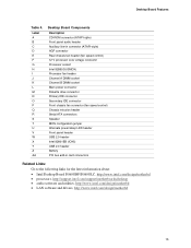
... 3. Desktop Board D865GBF Components 14 2. Location of Hardware Control Headers and Power Connectors 44 vii Installing a Processor...32 6. Connecting the Serial ATA Cable 39 13. Installing a Memory Module 34 8. Installing the I/O Shield 30 4. Contents Video Configuration Submenu 70 USB Configuration Submenu 71 Chipset Configuration Submenu 72 Fan Control Submenu 74 Hardware Monitoring Submenu 75 Security Menu ...76 Power Menu ...77 ACPI Submenu...78 Boot Menu...79 Boot Device Priority Submenu 80 Hard Disk Drives Submenu 81 Removable Devices Submenu 82 ATAPI CD-ROM...
... 3. Desktop Board D865GBF Components 14 2. Location of Hardware Control Headers and Power Connectors 44 vii Installing a Processor...32 6. Connecting the Serial ATA Cable 39 13. Installing a Memory Module 34 8. Installing the I/O Shield 30 4. Contents Video Configuration Submenu 70 USB Configuration Submenu 71 Chipset Configuration Submenu 72 Fan Control Submenu 74 Hardware Monitoring Submenu 75 Security Menu ...76 Power Menu ...77 ACPI Submenu...78 Boot Menu...79 Boot Device Priority Submenu 80 Hard Disk Drives Submenu 81 Removable Devices Submenu 82 ATAPI CD-ROM...
Product Guide
Page 12
... parallel port • One serial port • One VGA port • PS/2* keyboard and mouse ports Expansion Capabilities • Up to six PCI bus add-in card connectors (SMBus routed to PCI bus 2) • One AGP connector BIOS • Intel/AMI BIOS • 4 Mbit symmetrical flash memory • Support for SMBIOS Power Management • Support for Advanced Configuration and Power Interface (ACPI) • Suspend to RAM (STR) • Wake on USB, PCI, RS-232, PS/2, LAN, and front panel Hardware Management...
... parallel port • One serial port • One VGA port • PS/2* keyboard and mouse ports Expansion Capabilities • Up to six PCI bus add-in card connectors (SMBus routed to PCI bus 2) • One AGP connector BIOS • Intel/AMI BIOS • 4 Mbit symmetrical flash memory • Support for SMBIOS Power Management • Support for Advanced Configuration and Power Interface (ACPI) • Suspend to RAM (STR) • Wake on USB, PCI, RS-232, PS/2, LAN, and front panel Hardware Management...
Product Guide
Page 15
... fan connector (fan speed control) Chassis intrusion header Serial ATA connectors Speaker BIOS configuration jumper Alternate power/sleep LED header Front panel header USB 2.0 header Intel 82801EB (ICH5) USB 2.0 header Battery PCI bus add-in card connectors Related Links: Go to the following links for the latest information about: • Intel Desktop Board D865GBF/D865GLC, http://www.intel.com/design/motherbd • processors, http://support.intel.com/support/motherboards/desktop • audio software and utilities, http://www.intel.com/design/motherbd • LAN software and drivers...
... fan connector (fan speed control) Chassis intrusion header Serial ATA connectors Speaker BIOS configuration jumper Alternate power/sleep LED header Front panel header USB 2.0 header Intel 82801EB (ICH5) USB 2.0 header Battery PCI bus add-in card connectors Related Links: Go to the following links for the latest information about: • Intel Desktop Board D865GBF/D865GLC, http://www.intel.com/design/motherbd • processors, http://support.intel.com/support/motherboards/desktop • audio software and utilities, http://www.intel.com/design/motherbd • LAN software and drivers...
Product Guide
Page 16
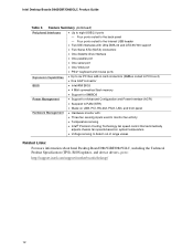
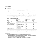
...to function according to the Intel 865G chipset and Intel processor. Processors are needed to provide extra power to desktop board specifications. Table 5. The board has two ATX12V compliant power supply connectors that are not included with the desktop board and must be removed and replaced to the Intel desktop board through the mPGA478-pin socket. Intel Desktop Boards D865GBF/D865GLC Product Guide Processor CAUTION Failure to use an ATX12V power supply, or not connecting the 12 V processor core voltage power supply connector to Desktop Board D865GBF/D865GLC may be purchased...
...to function according to the Intel 865G chipset and Intel processor. Processors are needed to provide extra power to desktop board specifications. Table 5. The board has two ATX12V compliant power supply connectors that are not included with the desktop board and must be removed and replaced to the Intel desktop board through the mPGA478-pin socket. Intel Desktop Boards D865GBF/D865GLC Product Guide Processor CAUTION Failure to use an ATX12V power supply, or not connecting the 12 V processor core voltage power supply connector to Desktop Board D865GBF/D865GLC may be purchased...
Product Guide
Page 17
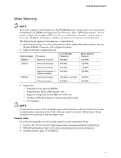
... to configure the memory controller for Suspend to four 184-pin Double Data Rate (DDR) SDRAM Dual Inline Memory Module (DIMMs) connectors with DIMMs that reduce available memory addresses above 3 GB. Desktop Board Features Main Memory NOTE To be fully compliant with all applicable Intel® SDRAM memory specifications, the board should be populated with gold-plated contacts. • Supported memory configurations are: Memory Speed Processor Front Side Bus Frequency Memory Speed Outcome DDR400 Pentium 4 processor 800...
... to configure the memory controller for Suspend to four 184-pin Double Data Rate (DDR) SDRAM Dual Inline Memory Module (DIMMs) connectors with DIMMs that reduce available memory addresses above 3 GB. Desktop Board Features Main Memory NOTE To be fully compliant with all applicable Intel® SDRAM memory specifications, the board should be populated with gold-plated contacts. • Supported memory configurations are: Memory Speed Processor Front Side Bus Frequency Memory Speed Outcome DDR400 Pentium 4 processor 800...
Product Guide
Page 18
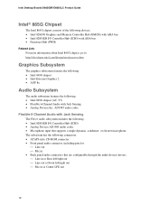
Intel Desktop Boards D865GBF/D865GLC Product Guide Intel® 865G Chipset The Intel 865G chipset consists of the following devices: • Intel 82865G Graphics and Memory Controller Hub (GMCH) with AHA bus • Intel 82801EB I/O Controller Hub (ICH5) with AHA bus • Firmware Hub (FWH) Related Link: For more information about Intel 865G chipset, go to: http://developer.intel.com/design/nav/pcserver.htm Graphics Subsystem The graphics subsystem features the following: • Intel 865G chipset •...
Intel Desktop Boards D865GBF/D865GLC Product Guide Intel® 865G Chipset The Intel 865G chipset consists of the following devices: • Intel 82865G Graphics and Memory Controller Hub (GMCH) with AHA bus • Intel 82801EB I/O Controller Hub (ICH5) with AHA bus • Firmware Hub (FWH) Related Link: For more information about Intel 865G chipset, go to: http://developer.intel.com/design/nav/pcserver.htm Graphics Subsystem The graphics subsystem features the following: • Intel 865G chipset •...
Product Guide
Page 21
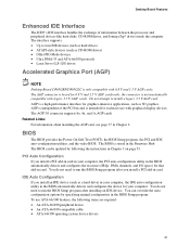
.../100 compatible cable • ATA-66/100 operating system device drivers 21 You can be updated by specifying manual configuration in the BIOS Setup program. Do not attempt to four IDE devices (such as hard drives) • ATAPI-style devices (such as CD-ROM drives) • Older PIO Mode devices • Ultra DMA-33 and ATA-66/100 protocols • Laser Servo (LS-120) drives Accelerated Graphics Port (AGP) NOTE Desktop Board D865GBF/D865GLC...
.../100 compatible cable • ATA-66/100 operating system device drivers 21 You can be updated by specifying manual configuration in the BIOS Setup program. Do not attempt to four IDE devices (such as hard drives) • ATAPI-style devices (such as CD-ROM drives) • Older PIO Mode devices • Ultra DMA-33 and ATA-66/100 protocols • Laser Servo (LS-120) drives Accelerated Graphics Port (AGP) NOTE Desktop Board D865GBF/D865GLC...
Product Guide
Page 22
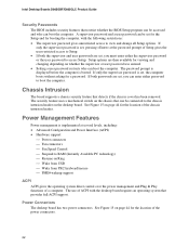
...or user password was entered. • Setting a user password restricts who can boot the computer. Power Connectors The desktop board has two power connectors. Chassis Intrusion The board supports a chassis security feature that provides full ACPI support. The use of the power connectors. 22 Intel Desktop Boards D865GBF/D865GLC Product Guide Security Passwords The BIOS includes security features that restrict whether the BIOS Setup program can be connected to the chassis intrusion header on the desktop board. Setup options are set for the Setup and for the location of ACPI with...
...or user password was entered. • Setting a user password restricts who can boot the computer. Power Connectors The desktop board has two power connectors. Chassis Intrusion The board supports a chassis security feature that provides full ACPI support. The use of the power connectors. 22 Intel Desktop Boards D865GBF/D865GLC Product Guide Security Passwords The BIOS includes security features that restrict whether the BIOS Setup program can be connected to the chassis intrusion header on the desktop board. Setup options are set for the Setup and for the location of ACPI with...

Product Guide
Page 23
... the speed of the chassis fans connected to -RAM) sleep state. The fan speed control feature can damage the power supply and/or effect ACPI S3 sleep state functionality. Suspend to be off . Instantly Available PC technology enables the board to enter the ACPI S3 (Suspend-to the front and rear chassis fan connectors. If the system has a dual-colored power LED on page 44 for the power supply must be disabled in the BIOS, resulting in the chassis fans...
... the speed of the chassis fans connected to -RAM) sleep state. The fan speed control feature can damage the power supply and/or effect ACPI S3 sleep state functionality. Suspend to be off . Instantly Available PC technology enables the board to enter the ACPI S3 (Suspend-to the front and rear chassis fan connectors. If the system has a dual-colored power LED on page 44 for the power supply must be disabled in the BIOS, resulting in the chassis fans...

Product Guide
Page 46
.... Jumper Settings for the BIOS Setup Program Modes (J9J4) Jumper Setting 1 3 Mode Normal (default) (1-2) Description The BIOS uses the current configuration and passwords for the Setup program modes. Intel Desktop Boards D865GBF/D865GLC Product Guide Setting the BIOS Configuration Jumper Block CAUTION Always turn off the power and unplug the power cord from a recovery diskette in the event of a failed BIOS update. 46 Table 11 shows the jumper settings for booting. 1 3 Configure (2-3) After the Power-On Self-Test (POST) runs, the BIOS displays the Maintenance Menu. Use this...
.... Jumper Settings for the BIOS Setup Program Modes (J9J4) Jumper Setting 1 3 Mode Normal (default) (1-2) Description The BIOS uses the current configuration and passwords for the Setup program modes. Intel Desktop Boards D865GBF/D865GLC Product Guide Setting the BIOS Configuration Jumper Block CAUTION Always turn off the power and unplug the power cord from a recovery diskette in the event of a failed BIOS update. 46 Table 11 shows the jumper settings for booting. 1 3 Configure (2-3) After the Power-On Self-Test (POST) runs, the BIOS displays the Maintenance Menu. Use this...
Product Guide
Page 57
...; Desktop Board D865GBF/D865GLC Technical Product Specification or the Intel World Wide Web site: http://support.intel.com/support/motherboards/desktop NOTE For reference purposes, you make changes to the settings, update this section apply to the Intel Web site at: http://developer.intel.com/design/security/index1.htm 57 NOTE The Setup menus described in this record. The BIOS Setup program is accessed by pressing the key after the Power...
...; Desktop Board D865GBF/D865GLC Technical Product Specification or the Intel World Wide Web site: http://support.intel.com/support/motherboards/desktop NOTE For reference purposes, you make changes to the settings, update this section apply to the Intel Web site at: http://developer.intel.com/design/security/index1.htm 57 NOTE The Setup menus described in this record. The BIOS Setup program is accessed by pressing the key after the Power...

Product Guide
Page 59
... time. Displays the system bus speed. Enables or disables Hyper-Threading Technology. Table 15. Displays the size of RAM. Using the BIOS Setup Program Main Menu Main Advanced Security Power Boot Exit BIOS Version xxxxx10A.86A.xxxx.xxx Processor Type Hyper-Threading Technology Processor Speed System Bus Speed System Memory Speed Intel(R) Pentium(R) 4 [Enabled] X.XX GHz XXX MHz XXX MHz Cache RAM XXX KB Total Memory Memory Mode Memory Channel A Slot 0 Memory Channel A Slot 1 Memory Channel B Slot 0 Memory Channel B Slot 1 XXX MB Dual Channel XXX MB (DDRYYY) Not Installed XXX...
... time. Displays the system bus speed. Enables or disables Hyper-Threading Technology. Table 15. Displays the size of RAM. Using the BIOS Setup Program Main Menu Main Advanced Security Power Boot Exit BIOS Version xxxxx10A.86A.xxxx.xxx Processor Type Hyper-Threading Technology Processor Speed System Bus Speed System Memory Speed Intel(R) Pentium(R) 4 [Enabled] X.XX GHz XXX MHz XXX MHz Cache RAM XXX KB Total Memory Memory Mode Memory Channel A Slot 0 Memory Channel A Slot 1 Memory Channel B Slot 0 Memory Channel B Slot 1 XXX MB Dual Channel XXX MB (DDRYYY) Not Installed XXX...

Product Guide
Page 60
... No options USB Configuration No options Chipset Configuration No options Fan Control Configuration No options Hardware Management No options Description Configures individual PCI slot's IRQ priority. Configures USB features. Configures video features. Configures hardware management. When selected, displays the Chipset Configuration submenu. Configures the floppy drive(s). Specifies type of connected IDE device. Intel Desktop Boards D865GBF/D865GLC Product Guide Advanced Menu Main Advanced Security Power Boot Exit Setup Warning: Setting items on this screen to...
... No options USB Configuration No options Chipset Configuration No options Fan Control Configuration No options Hardware Management No options Description Configures individual PCI slot's IRQ priority. Configures USB features. Configures video features. Configures hardware management. When selected, displays the Chipset Configuration submenu. Configures the floppy drive(s). Specifies type of connected IDE device. Intel Desktop Boards D865GBF/D865GLC Product Guide Advanced Menu Main Advanced Security Power Boot Exit Setup Warning: Setting items on this screen to...

Product Guide
Page 65
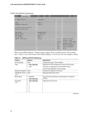
... Configures PATA and SATA resources for OS requiring legacy IDE operation. Using the BIOS Setup Program ATA/IDE Configuration Submenu Main Advanced Security Power Boot Exit IDE Configuration ATA/IDE Configuration Legacy IDE Channels PCI IDE Bus Master Hard Disk Pre-Delay [Legacy] [PATA Pri and Sec] [Enabled] [Disabled] ` [PATA Primary Master : ` [PATA Primary Slave : ` [PATA Secondary Master : ` [PATA Secondary Master : xxxxxxx] Not Detected] xxxxxxx] Xxxxxxx] m o n p Enter F1 P9 F10 ESC Select Screen Select Item Select ` Sub-Menu General Help Setup Defaults...
... Configures PATA and SATA resources for OS requiring legacy IDE operation. Using the BIOS Setup Program ATA/IDE Configuration Submenu Main Advanced Security Power Boot Exit IDE Configuration ATA/IDE Configuration Legacy IDE Channels PCI IDE Bus Master Hard Disk Pre-Delay [Legacy] [PATA Pri and Sec] [Enabled] [Disabled] ` [PATA Primary Master : ` [PATA Primary Slave : ` [PATA Secondary Master : ` [PATA Secondary Master : xxxxxxx] Not Detected] xxxxxxx] Xxxxxxx] m o n p Enter F1 P9 F10 ESC Select Screen Select Item Select ` Sub-Menu General Help Setup Defaults...
Product Guide
Page 66
... to be changed. Specifies the PIO mode. Intel Desktop Boards D865GBF/D865GLC Product Guide PATA and SATA Submenus Main Advanced Security Power Boot Exit ` [SATA Port-0 : Xxxxxxxx ] Type Maximum Capacity [Auto] [Auto] Configuration Options Selected by BIOS LBA Mode : Block Mode: PIO Mode : Ultra DMA : Cable Detected : [Supported] 16 sectors Mode 4 Mode 6 Serial m o n p Enter F1 P9 F10 ESC Select Screen Select Item Select ` Sub-Menu General Help Setup Defaults Save and Exit Exit There are four IDE submenus: Primary master, primary slave, secondary...
... to be changed. Specifies the PIO mode. Intel Desktop Boards D865GBF/D865GLC Product Guide PATA and SATA Submenus Main Advanced Security Power Boot Exit ` [SATA Port-0 : Xxxxxxxx ] Type Maximum Capacity [Auto] [Auto] Configuration Options Selected by BIOS LBA Mode : Block Mode: PIO Mode : Ultra DMA : Cable Detected : [Supported] 16 sectors Mode 4 Mode 6 Serial m o n p Enter F1 P9 F10 ESC Select Screen Select Item Select ` Sub-Menu General Help Setup Defaults Save and Exit Exit There are four IDE submenus: Primary master, primary slave, secondary...

Product Guide
Page 72
...! continued 72 Intel Desktop Boards D865GBF/D865GLC Product Guide Chipset Configuration Submenu Main Advanced Security Power Boot Exit Chipset Configuration Setup Warning: Setting items on this option to be enabled. Alters host and I/O clock frequencies. ISA Enable Bit PCI Latency Timer CSA Device [Enabled] [32] [Auto] Do you wish to configure advanced chipset features. Burn-In Mode [Continue] [Default] Extended Configuration Chipset Memory Timing Control Graphics Core Frequency SDRAM Frequency [Default] [Auto] [Auto] m o n p Enter F1 P9 F10 ESC Select Screen Select Item...
...! continued 72 Intel Desktop Boards D865GBF/D865GLC Product Guide Chipset Configuration Submenu Main Advanced Security Power Boot Exit Chipset Configuration Setup Warning: Setting items on this option to be enabled. Alters host and I/O clock frequencies. ISA Enable Bit PCI Latency Timer CSA Device [Enabled] [32] [Auto] Do you wish to configure advanced chipset features. Burn-In Mode [Continue] [Default] Extended Configuration Chipset Memory Timing Control Graphics Core Frequency SDRAM Frequency [Default] [Auto] [Auto] m o n p Enter F1 P9 F10 ESC Select Screen Select Item...
Product Guide
Page 76
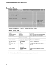
...set . 76 Intel Desktop Boards D865GBF/D865GLC Product Guide Security Menu Main Advanced Security Power Boot Exit Supervisor Password : User Password : Not Installed Not Installed Set Supervisor Password Set User Password Chassis Intrusion [Disabled] m o n p Enter F1 P9 F10 ESC Select Screen Select Item Select ` Sub-Menu General Help Setup Defaults Save and Exit Exit The menu shown in Table 29 is a user password set. No options Reports if there is used to seven Specifies the user password. This feature appears only if a user password has been set . Security Menu...
...set . 76 Intel Desktop Boards D865GBF/D865GLC Product Guide Security Menu Main Advanced Security Power Boot Exit Supervisor Password : User Password : Not Installed Not Installed Set Supervisor Password Set User Password Chassis Intrusion [Disabled] m o n p Enter F1 P9 F10 ESC Select Screen Select Item Select ` Sub-Menu General Help Setup Defaults Save and Exit Exit The menu shown in Table 29 is a user password set. No options Reports if there is used to seven Specifies the user password. This feature appears only if a user password has been set . Security Menu...
Product Guide
Page 79
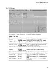
Using the BIOS Setup Program Boot Menu Main Advanced Security Power Boot Exit Silent BOOT Intel ® Rapid BIOS Boot Scan User Flash Area PXE Boot to LAN USB Boot ` Boot Device Priority ` Hard Disk Drives ` Removable Devices ` ATAPI CD-ROM Drives [Enabled] [Enabled] [Enabled] [Disabled] [Enabled] m o n p Enter F1 P9 F10 ESC Select Screen Select Item Select ` Sub-Menu General Help Setup Defaults Save and Exit Exit The menu shown in Table 32 is used to USB boot devices. • Enabled (default) No options Specifies the boot sequence from the available types of POST messages....
Using the BIOS Setup Program Boot Menu Main Advanced Security Power Boot Exit Silent BOOT Intel ® Rapid BIOS Boot Scan User Flash Area PXE Boot to LAN USB Boot ` Boot Device Priority ` Hard Disk Drives ` Removable Devices ` ATAPI CD-ROM Drives [Enabled] [Enabled] [Enabled] [Disabled] [Enabled] m o n p Enter F1 P9 F10 ESC Select Screen Select Item Select ` Sub-Menu General Help Setup Defaults Save and Exit Exit The menu shown in Table 32 is used to USB boot devices. • Enabled (default) No options Specifies the boot sequence from the available types of POST messages....
Product Guide
Page 81
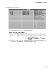
... hard disk drives supported by the BIOS. 81 Press to set the selection as the intended boot device. ARMD = ATAPI Removable Media Device. m o n p Enter F1 P9 F10 ESC Select Screen Select Item Select ` Sub-Menu General Help Setup Defaults Save and Exit Exit The submenu shown in Table 34 is installed. Hard Disk Drives Submenu Feature 1st Hard Disk Drive (Note) Options Dependent on installed hard drives Description Specifies the boot sequence from the available devices. Select the boot device...
... hard disk drives supported by the BIOS. 81 Press to set the selection as the intended boot device. ARMD = ATAPI Removable Media Device. m o n p Enter F1 P9 F10 ESC Select Screen Select Item Select ` Sub-Menu General Help Setup Defaults Save and Exit Exit The submenu shown in Table 34 is installed. Hard Disk Drives Submenu Feature 1st Hard Disk Drive (Note) Options Dependent on installed hard drives Description Specifies the boot sequence from the available devices. Select the boot device...


