

Product Specification
Page 2
... contain design defects or errors known as the property of Intel Corporation or its subsidiaries in the Intel Desktop Board D845PEBT2 Specification Update before placing your distributor to only the standard Intel Desktop Board D845PEBT2 with BIOS identifier BT84520A.86A. Intel may make changes to deviate from : Intel Corporation P.O. Intel Corporation may be published in the United States and...
... contain design defects or errors known as the property of Intel Corporation or its subsidiaries in the Intel Desktop Board D845PEBT2 Specification Update before placing your distributor to only the standard Intel Desktop Board D845PEBT2 with BIOS identifier BT84520A.86A. Intel may make changes to deviate from : Intel Corporation P.O. Intel Corporation may be published in the United States and...

Product Specification
Page 3
... call attention to help you avoid damaging hardware or losing data. iii Preface This Technical Product Specification (TPS) specifies the Intel Desktop Board D845PEBT2 layout, components, connectors, power and environmental requirements, and BIOS. The TPS describes the standard product and available manufacturing options. Intended Audience The TPS is specifically not intended for general...
... call attention to help you avoid damaging hardware or losing data. iii Preface This Technical Product Specification (TPS) specifies the Intel Desktop Board D845PEBT2 layout, components, connectors, power and environmental requirements, and BIOS. The TPS describes the standard product and available manufacturing options. Intended Audience The TPS is specifically not intended for general...

Product Specification
Page 6
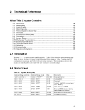
Intel Desktop Board D845PEBT2 Technical Product Specification 2 Technical Reference 2.1 Introduction...45 2.2 Memory Map ...45 2.3 Fixed I/O Map...46 2.4 DMA Channels ...47 2.5 PCI Configuration Space Map 47 2.6 ... 52 2.8.2 Internal I/O Connectors 56 2.8.3 External I/O Connectors 68 2.9 Jumper Blocks...72 2.9.1 Front Panel Audio Connector/Jumper Block 72 2.9.2 BIOS Setup Configuration Jumper Block 73 2.10 Mechanical Considerations 74 2.10.1 D845PEBT2 Form Factor 74 2.10.2 I/O Shield ...76 2.11 Electrical Considerations 79 2.11.1 Power Consumption 79 2.11.2 Add-in Board Considerations...
Intel Desktop Board D845PEBT2 Technical Product Specification 2 Technical Reference 2.1 Introduction...45 2.2 Memory Map ...45 2.3 Fixed I/O Map...46 2.4 DMA Channels ...47 2.5 PCI Configuration Space Map 47 2.6 ... 52 2.8.2 Internal I/O Connectors 56 2.8.3 External I/O Connectors 68 2.9 Jumper Blocks...72 2.9.1 Front Panel Audio Connector/Jumper Block 72 2.9.2 BIOS Setup Configuration Jumper Block 73 2.10 Mechanical Considerations 74 2.10.1 D845PEBT2 Form Factor 74 2.10.2 I/O Shield ...76 2.11 Electrical Considerations 79 2.11.1 Power Consumption 79 2.11.2 Add-in Board Considerations...

Product Specification
Page 7
Contents 3.10 Fast Booting Systems with Intel® Rapid BIOS Boot 94 3.10.1 Peripheral Selection and Configuration 94 3.10.2 Intel Rapid BIOS Boot 95 3.11 BIOS Security Features 96 4 BIOS Setup Program 4.1 Introduction...97 4.2 Maintenance Menu ...98 4.3 Main Menu...99 4.4 Advanced Menu...100 4.4.1 PCI Configuration Submenu 101 4.4.2 Boot ... Removable Devices Submenu 117 4.7.4 ATAPI CD-ROM Drives Submenu 118 4.8 Exit Menu ...118 5 Error Messages and Beep Codes 5.1 BIOS Error Messages 119 5.2 Port 80h POST Codes 121 5.3 Bus Initialization Checkpoints 125 5.4 Speaker ...126...
Contents 3.10 Fast Booting Systems with Intel® Rapid BIOS Boot 94 3.10.1 Peripheral Selection and Configuration 94 3.10.2 Intel Rapid BIOS Boot 95 3.11 BIOS Security Features 96 4 BIOS Setup Program 4.1 Introduction...97 4.2 Maintenance Menu ...98 4.3 Main Menu...99 4.4 Advanced Menu...100 4.4.1 PCI Configuration Submenu 101 4.4.2 Boot ... Removable Devices Submenu 117 4.7.4 ATAPI CD-ROM Drives Submenu 118 4.8 Exit Menu ...118 5 Error Messages and Beep Codes 5.1 BIOS Error Messages 119 5.2 Port 80h POST Codes 121 5.3 Bus Initialization Checkpoints 125 5.4 Speaker ...126...

Product Specification
Page 9
... 52. EMC Regulations...86 62. BIOS Setup Program Menu Bar 97 65. Mic In Connector ...55 28. LAN Connector ...55 29. Rear Chassis Fan Connector 59 32. States for 6-Channel Audio 55 27. Desktop Board D845PEBT2 Environmental Specifications 85 60. States for... Components 84 59. BIOS Setup Configuration Jumper Settings 73 54. Safety Regulations ...86 61. Audio Line In Connector 55 26. ...
... 52. EMC Regulations...86 62. BIOS Setup Program Menu Bar 97 65. Mic In Connector ...55 28. LAN Connector ...55 29. Rear Chassis Fan Connector 59 32. States for 6-Channel Audio 55 27. Desktop Board D845PEBT2 Environmental Specifications 85 60. States for... Components 84 59. BIOS Setup Configuration Jumper Settings 73 54. Safety Regulations ...86 61. Audio Line In Connector 55 26. ...

Product Specification
Page 10
... Drives Submenu 118 88. Upper Nibble High Byte Functions 125 95. Advanced Menu...100 69. BIOS Error Messages 119 90. IDE Configuration Submenu 105 73. Power Menu ...114 82. ACPI Submenu...114 83. Intel Desktop Board D845PEBT2 Technical Product Specification 67. Lower Nibble High Byte Functions 126 96. Main Menu...99 68. Peripheral...
... Drives Submenu 118 88. Upper Nibble High Byte Functions 125 95. Advanced Menu...100 69. BIOS Error Messages 119 90. IDE Configuration Submenu 105 73. Power Menu ...114 82. ACPI Submenu...114 83. Intel Desktop Board D845PEBT2 Technical Product Specification 67. Lower Nibble High Byte Functions 126 96. Main Menu...99 68. Peripheral...
Product Specification
Page 13
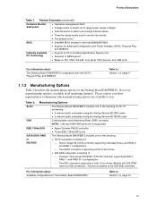
...Table 2 describes the manufacturing options for the Desktop Board D845PEBT2 Refer to monitor fan activity • Fan speed control BIOS • Intel/AMI BIOS (resident in all marketing channels. Manufacturing Options Audio The Desktop Board D845PEBT2 includes one of the following for AC '97 processing... are connected to determine which manufacturing options are not supported. Please contact your Intel representative to the IDE RAID controller) For information about The Desktop Board D845PEBT2's compliance level with IDE RAID have four IDE connectors. Table 2. Silicon Image...
...Table 2 describes the manufacturing options for the Desktop Board D845PEBT2 Refer to monitor fan activity • Fan speed control BIOS • Intel/AMI BIOS (resident in all marketing channels. Manufacturing Options Audio The Desktop Board D845PEBT2 includes one of the following for AC '97 processing... are connected to determine which manufacturing options are not supported. Please contact your Intel representative to the IDE RAID controller) For information about The Desktop Board D845PEBT2's compliance level with IDE RAID have four IDE connectors. Table 2. Silicon Image...
Product Specification
Page 17
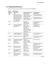
... of Electrical and Electronic Engineers. Version 1.2, August 2000, Intel Corporation. Version 2.1, June 2002, Intel Corporation. Version 2.0a, March 31, 2002, Compaq Computer Corporation, Intel Corporation, Microsoft Corporation, Phoenix Technologies Limited, and Toshiba Corporation... the specifications applicable to the Desktop Board D845PEBT2. Version 1.0, August 4, 1999, Intel Corporation. Amendment 1 AC '97 Audio Codec '97 ACPI Advanced Configuration and Power Interface Specification AGP AMI BIOS Accelerated Graphics Port Interface Specification AMIBIOS Desktop ...
... of Electrical and Electronic Engineers. Version 1.2, August 2000, Intel Corporation. Version 2.1, June 2002, Intel Corporation. Version 2.0a, March 31, 2002, Compaq Computer Corporation, Intel Corporation, Microsoft Corporation, Phoenix Technologies Limited, and Toshiba Corporation... the specifications applicable to the Desktop Board D845PEBT2. Version 1.0, August 4, 1999, Intel Corporation. Amendment 1 AC '97 Audio Codec '97 ACPI Advanced Configuration and Power Interface Specification AGP AMI BIOS Accelerated Graphics Port Interface Specification AMIBIOS Desktop ...

Product Specification
Page 18
...Intel Corporation. Release 1.0a, October 10, 1996, Compaq computer Corp., Microsoft Corporation, and National Semiconductor Corp. Revision 1.1, December 18, 1998, PCI Special Interest Group. Version 1.0a, May 5, 1994, Compaq Computer Corporation, Phoenix Technologies Limited, and Intel...Intel Corporation. http://www.jedec.org/ http://www.jedec.org/ http://developer.intel.com/ technology/memory/ index.htm http://developer.intel...http://www.intel.com/ ...Intel Desktop Board D845PEBT2 Technical Product Specification Table 3. Revision 0.9, September 27, 2001, Intel...Unbuffered DIMM Intel ®...
...Intel Corporation. Release 1.0a, October 10, 1996, Compaq computer Corp., Microsoft Corporation, and National Semiconductor Corp. Revision 1.1, December 18, 1998, PCI Special Interest Group. Version 1.0a, May 5, 1994, Compaq Computer Corporation, Phoenix Technologies Limited, and Intel...Intel Corporation. http://www.jedec.org/ http://www.jedec.org/ http://developer.intel.com/ technology/memory/ index.htm http://developer.intel...http://www.intel.com/ ...Intel Desktop Board D845PEBT2 Technical Product Specification Table 3. Revision 0.9, September 27, 2001, Intel...Unbuffered DIMM Intel ®...

Product Specification
Page 19
..., American Megatrends Incorporated, Award Software International Incorporated, Compaq Computer Corporation, Dell Computer Corporation, Hewlett-Packard Company, Intel Corporation, International Business Machines Corporation, Phoenix Technologies Limited, and SystemSoft Corporation. Specifications (continued) Reference Name PXE ...: High Speed Serialized AT Attachment System Management BIOS Universal Host Controller Interface Design Guide Universal Serial Bus Specification Version, Revision Date and Ownership Version 2.1, September 20, 1999, Intel Corporation. Revision 1.0, August 29, 2001, ...
..., American Megatrends Incorporated, Award Software International Incorporated, Compaq Computer Corporation, Dell Computer Corporation, Hewlett-Packard Company, Intel Corporation, International Business Machines Corporation, Phoenix Technologies Limited, and SystemSoft Corporation. Specifications (continued) Reference Name PXE ...: High Speed Serialized AT Attachment System Management BIOS Universal Host Controller Interface Design Guide Universal Serial Bus Specification Version, Revision Date and Ownership Version 2.1, September 20, 1999, Intel Corporation. Revision 1.0, August 29, 2001, ...

Product Specification
Page 21
...settings for a maximum onboard capacity of tested memory. If non-SPD memory is installed, the BIOS will attempt to correctly configure the memory settings, but this Desktop Board. http://developer.intel.com/design/motherbd/bt2/bt2_mem.htm • Minimum total system memory: 64 MB •... the Desktop Board should be impacted or the DIMMs may not function under the determined frequency. Product Description 1.6 System Memory The Desktop Board D845PEBT2 has two DIMM sockets and supports the following memory features: • 2.5 V (only) 184-pin DDR SDRAM DIMMs with gold-plated ...
...settings for a maximum onboard capacity of tested memory. If non-SPD memory is installed, the BIOS will attempt to correctly configure the memory settings, but this Desktop Board. http://developer.intel.com/design/motherbd/bt2/bt2_mem.htm • Minimum total system memory: 64 MB •... the Desktop Board should be impacted or the DIMMs may not function under the determined frequency. Product Description 1.6 System Memory The Desktop Board D845PEBT2 has two DIMM sockets and supports the following memory features: • 2.5 V (only) 184-pin DDR SDRAM DIMMs with gold-plated ...
Product Specification
Page 23
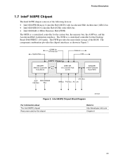
..., the AGP bus, and the Accelerated Hub Architecture interface. Intel 845PE Chipset Block Diagram OM15029 For information about The Intel 845PE chipset Resources used by the chipset Refer to http://developer.intel.com Chapter 2 23 System Bus UDMA 33 ATA-66/100... AHA Bus 82801DB I /O paths. Product Description 1.7 Intel® 845PE Chipset The Intel 845PE chipset consists of the BIOS. The component combination provides the chipset interfaces as shown in Figure 3. The ICH4 is a centralized controller for the Desktop Board D845PEBT2's I /O Controller Hub (ICH4) 82802AB 4 Mbit ...
..., the AGP bus, and the Accelerated Hub Architecture interface. Intel 845PE Chipset Block Diagram OM15029 For information about The Intel 845PE chipset Resources used by the chipset Refer to http://developer.intel.com Chapter 2 23 System Bus UDMA 33 ATA-66/100... AHA Bus 82801DB I /O paths. Product Description 1.7 Intel® 845PE Chipset The Intel 845PE chipset consists of the BIOS. The component combination provides the chipset interfaces as shown in Figure 3. The ICH4 is a centralized controller for the Desktop Board D845PEBT2's I /O Controller Hub (ICH4) 82802AB 4 Mbit ...
Product Specification
Page 25
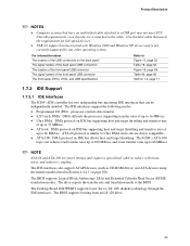
...Extended Cylinder Head Sector (ECHS) translation modes. The ICH4's ATA-100 logic can be independently enabled. ATA-66 protocol is similar to the BIOS. The IDE interfaces support the following modes: • Programmed I/O (PIO): processor controls data transfer. • 8237-style DMA: DMA offloads.... For information about The location of the USB connectors on page 106. The Desktop Board D845PEBT2 supports Laser Servo (LS-120) diskette technology through the IDE interfaces. The BIOS supports booting from an LS-120 drive. 25 Product Description ✏ NOTES • Computer...
...Extended Cylinder Head Sector (ECHS) translation modes. The ICH4's ATA-100 logic can be independently enabled. ATA-66 protocol is similar to the BIOS. The IDE interfaces support the following modes: • Programmed I/O (PIO): processor controls data transfer. • 8237-style DMA: DMA offloads.... For information about The location of the USB connectors on page 106. The Desktop Board D845PEBT2 supports Laser Servo (LS-120) diskette technology through the IDE interfaces. The BIOS supports booting from an LS-120 drive. 25 Product Description ✏ NOTES • Computer...
Product Specification
Page 26
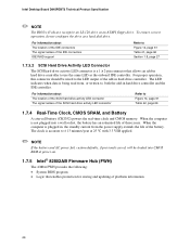
...8226; System BIOS program • Logic that allows an add-in hard drive controller to Figure 14, page 61 Table 42, page 66 1.7.4 Real-Time Clock, CMOS SRAM, and Battery A coin-cell battery (CR2032) powers the real-time clock and CMOS memory. Intel Desktop Board D845PEBT2 Technical Product Specification... ✏ NOTE The BIOS will be wired to the LED output of the SCSI hard drive activity LED connector Refer to use the same ...
...8226; System BIOS program • Logic that allows an add-in hard drive controller to Figure 14, page 61 Table 42, page 66 1.7.4 Real-Time Clock, CMOS SRAM, and Battery A coin-cell battery (CR2032) powers the real-time clock and CMOS memory. Intel Desktop Board D845PEBT2 Technical Product Specification... ✏ NOTE The BIOS will be wired to the LED output of the SCSI hard drive activity LED connector Refer to use the same ...
Product Specification
Page 27
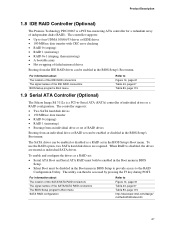
... individual SATA drives. To use the RAID option, two SATA hard disk drives are treated as a RAID set can be enabled or disabled in the BIOS Setup's Boot menu. Product Description 1.8 IDE RAID Controller (Optional) The Promise Technology PDC20267 is a PCI bus-mastering ATA controller for a redundant array of the ... program's Boot menu SATA RAID configuration Refer to Figure 14, page 61 Table 43, page 67 Table 83, page 115 http://developer.intel.com/design/ motherbd/bt2/index.htm 27 The controller supports: • Up to four UDMA 100/66/33 drives or EIDE drives • 100 MB...
... individual SATA drives. To use the RAID option, two SATA hard disk drives are treated as a RAID set can be enabled or disabled in the BIOS Setup's Boot menu. Product Description 1.8 IDE RAID Controller (Optional) The Promise Technology PDC20267 is a PCI bus-mastering ATA controller for a redundant array of the ... program's Boot menu SATA RAID configuration Refer to Figure 14, page 61 Table 43, page 67 Table 83, page 115 http://developer.intel.com/design/ motherbd/bt2/index.htm 27 The controller supports: • Up to four UDMA 100/66/33 drives or EIDE drives • 100 MB...
Product Specification
Page 28
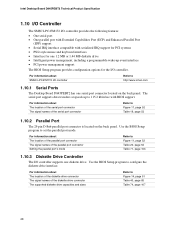
Intel Desktop Board D845PEBT2 Technical Product Specification 1.10 I/O Controller The SMSC LPC47M172 I/O controller provides the following features: • One serial port • One parallel port with Extended Capabilities Port (ECP) and Enhanced Parallel Port (EPP) support • Serial IRQ interface compatible with BIOS ... SMSC LPC47M172 I/O controller Refer to configure the diskette drive interface. Use the BIOS Setup program to http://www.smsc.com 1.10.1 Serial Ports The Desktop Board D845PEBT2 has one diskette drive. For information about The location of the parallel port ...
Intel Desktop Board D845PEBT2 Technical Product Specification 1.10 I/O Controller The SMSC LPC47M172 I/O controller provides the following features: • One serial port • One parallel port with Extended Capabilities Port (ECP) and Enhanced Parallel Port (EPP) support • Serial IRQ interface compatible with BIOS ... SMSC LPC47M172 I/O controller Refer to configure the diskette drive interface. Use the BIOS Setup program to http://www.smsc.com 1.10.1 Serial Ports The Desktop Board D845PEBT2 has one diskette drive. For information about The location of the parallel port ...

Product Specification
Page 40
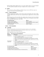
...# Power switch PS/2 devices RTC alarm USB ...from this option to Power On will enable a wake-up event from LAN in the BIOS Setup program. In addition, software, drivers, and peripherals must fully support ACPI wake events. 1.16.2 Hardware Support CAUTION Ensure that provides full...and manufacturing options. Failure to Section 2.11.3 on Ring • Wake from USB • Wake from the +5 V standby line. Intel Desktop Board D845PEBT2 Technical Product Specification 1.16.1.2 Wake-up Devices and Events Table 8 lists the devices or specific events that can damage the power supply....
...# Power switch PS/2 devices RTC alarm USB ...from this option to Power On will enable a wake-up event from LAN in the BIOS Setup program. In addition, software, drivers, and peripherals must fully support ACPI wake events. 1.16.2 Hardware Support CAUTION Ensure that provides full...and manufacturing options. Failure to Section 2.11.3 on Ring • Wake from USB • Wake from the +5 V standby line. Intel Desktop Board D845PEBT2 Technical Product Specification 1.16.1.2 Wake-up Devices and Events Table 8 lists the devices or specific events that can damage the power supply....
Product Specification
Page 41
... to a chassis fan connector may result in the S0 or S1 state. For information about The power connector locations The power connector signal names The BIOS Setup program's Boot menu The ATX specification Refer to Figure 13, page 58 Table 30, page 59 and Table 33, page 60 Table 83, page... 115 Section 1.4, page 17 1.16.2.2 Fan Connectors CAUTION The processor fan must be set using the Last Power State feature in the BIOS Setup program's Boot menu. The method used depends on the type of telephony device (external or internal). ✏ NOTE The use of the fan connectors...
... to a chassis fan connector may result in the S0 or S1 state. For information about The power connector locations The power connector signal names The BIOS Setup program's Boot menu The ATX specification Refer to Figure 13, page 58 Table 30, page 59 and Table 33, page 60 Table 83, page... 115 Section 1.4, page 17 1.16.2.2 Fan Connectors CAUTION The processor fan must be set using the Last Power State feature in the BIOS Setup program's Boot menu. The method used depends on the type of telephony device (external or internal). ✏ NOTE The use of the fan connectors...

Product Specification
Page 44
Intel Desktop Board D845PEBT2 Technical Product Specification 1.16.2.8 Wake from PS/2 Devices PS/2 device activity wakes the computer from an ACPI S1 or S3 state. 1.16.2.9 PME# Wake-up Support When the PME# signal on the PCI bus is asserted, the computer wakes from an ACPI S1, S3, S4, or S5 state (with Wake on PME enabled in BIOS). 44
Intel Desktop Board D845PEBT2 Technical Product Specification 1.16.2.8 Wake from PS/2 Devices PS/2 device activity wakes the computer from an ACPI S1 or S3 state. 1.16.2.9 PME# Wake-up Support When the PME# signal on the PCI bus is asserted, the computer wakes from an ACPI S1, S3, S4, or S5 state (with Wake on PME enabled in BIOS). 44
Product Specification
Page 45
... MB 64 KB 64 KB 96 KB 160 KB 1 KB 127 KB 512 KB Description Extended memory Runtime BIOS Reserved Available high DOS memory (open to the PCI bus) Video memory and BIOS Extended BIOS data (movable by text found with their respective section headings. 2.2 Memory Map Table 10. System Memory Map Address...
... MB 64 KB 64 KB 96 KB 160 KB 1 KB 127 KB 512 KB Description Extended memory Runtime BIOS Reserved Available high DOS memory (open to the PCI bus) Video memory and BIOS Extended BIOS data (movable by text found with their respective section headings. 2.2 Memory Map Table 10. System Memory Map Address...


