
Product Specification
Page 91
...hard disk, a 1.44 MB diskette, or a CD-ROM, or from the file location on the Web. • Intel® Flash Memory Update Utility, which requires creation of a boot diskette and manual rebooting of the system. POST begins. 3. Using this utility, the BIOS can be updated from a file on the... Intel World Wide Web site: • Intel® Express BIOS Update utility, which are available on a 1.44 MB...
...hard disk, a 1.44 MB diskette, or a CD-ROM, or from the file location on the Web. • Intel® Flash Memory Update Utility, which requires creation of a boot diskette and manual rebooting of the system. POST begins. 3. Using this utility, the BIOS can be updated from a file on the... Intel World Wide Web site: • Intel® Express BIOS Update utility, which are available on a 1.44 MB...
Product Specification
Page 102
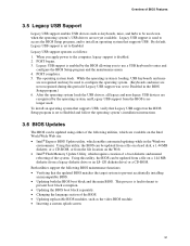
...select Advanced on the numeric keypad of the keyboard. 102 This option is appropriate when using a Plug and Play operating system. Intel Desktop Board D845PEBT2 Technical Product Specification Table 69. Boot Configuration Submenu Feature Plug & Play O/S Numlock Options • No (default) • ...Yes • Off • On (default) Description Specifies if manual configuration is for setting Plug and Play options and the...
...select Advanced on the numeric keypad of the keyboard. 102 This option is appropriate when using a Plug and Play operating system. Intel Desktop Board D845PEBT2 Technical Product Specification Table 69. Boot Configuration Submenu Feature Plug & Play O/S Numlock Options • No (default) • ...Yes • Off • On (default) Description Specifies if manual configuration is for setting Plug and Play options and the...
Product Specification
Page 111
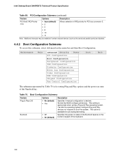
...range (within the bridge's assigned I/O range). • 32 (default) • 64 • 96 Allows you must reboot for configuring chipset options. Manual - continued 111 After changing this menu, select Advanced on the PC bus can hold the bus when another agent has requested the bus. • ... feature is displayed only if Extended Configuration is displayed only if the installed processor has a 533 MHz system bus. User Defined = Allows manual override of the detected memory frequency. • 266 MHz • 333 MHz (Note 2) NOTE: If SDRAM Frequency is for the change ...
...range (within the bridge's assigned I/O range). • 32 (default) • 64 • 96 Allows you must reboot for configuring chipset options. Manual - continued 111 After changing this menu, select Advanced on the PC bus can hold the bus when another agent has requested the bus. • ... feature is displayed only if Extended Configuration is displayed only if the installed processor has a 533 MHz system bus. User Defined = Allows manual override of the detected memory frequency. • 266 MHz • 333 MHz (Note 2) NOTE: If SDRAM Frequency is for the change ...

Product Specification
Page 112
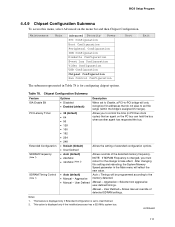
Intel Desktop Board D845PEBT2 Technical Product Specification Table 78. Selects the number of clock cycles required to address a column in Table 78 is set to Manual - After saving the BIOS settings and turning off . Selects the number of clock cycles between addressing a row and addressing a column. Selects the length of chassis ...
Intel Desktop Board D845PEBT2 Technical Product Specification Table 78. Selects the number of clock cycles required to address a column in Table 78 is set to Manual - After saving the BIOS settings and turning off . Selects the number of clock cycles between addressing a row and addressing a column. Selects the length of chassis ...

Product Guide
Page 4
Intel Desktop Boards D845PESV Product Guide 2 Installing and Replacing Desktop Board Components Before You Begin ...23 Installing the I/O Shield ...24 Installing and Removing the Desktop Board ... Configuring BIOS for Serial ATA RAID 39 The RAID Configuration Utility 40 Creating a Striped Set (RAID 0 41 Automatic Configuration 41 Manual Configuration 41 Creating a Mirrored Set (RAID 1 42 Automatic Configuration 42 Manual Configuration 43 Deleting the RAID Set 44 Rebuilding the Mirrored Set 44 Resolving Conflicts ...44 Loading the SATA RAID or...
Intel Desktop Boards D845PESV Product Guide 2 Installing and Replacing Desktop Board Components Before You Begin ...23 Installing the I/O Shield ...24 Installing and Removing the Desktop Board ... Configuring BIOS for Serial ATA RAID 39 The RAID Configuration Utility 40 Creating a Striped Set (RAID 0 41 Automatic Configuration 41 Manual Configuration 41 Creating a Mirrored Set (RAID 1 42 Automatic Configuration 42 Manual Configuration 43 Deleting the RAID Set 44 Rebuilding the Mirrored Set 44 Resolving Conflicts ...44 Loading the SATA RAID or...
Product Guide
Page 18
... If you install a PCI add-in card in card. You do not need to Setup. 18 Intel Desktop Board D845PEBT2 Product Guide Accelerated Graphics Port (AGP) ✏ NOTE Desktop Board D845PEBT2 is stored in the Firmware Hub. PCI Auto Configuration If you install an IDE device (such as 3D.../100 operating system device drivers Security Passwords The BIOS includes security features that add-in your computer. You can be updated by specifying manual configuration in cards. You do not need to view and change all Setup options. To use with the following the instructions in card...
... If you install a PCI add-in card in card. You do not need to Setup. 18 Intel Desktop Board D845PEBT2 Product Guide Accelerated Graphics Port (AGP) ✏ NOTE Desktop Board D845PEBT2 is stored in the Firmware Hub. PCI Auto Configuration If you install an IDE device (such as 3D.../100 operating system device drivers Security Passwords The BIOS includes security features that add-in your computer. You can be updated by specifying manual configuration in cards. You do not need to view and change all Setup options. To use with the following the instructions in card...

Product Guide
Page 25
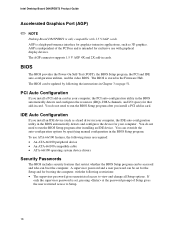
... its power source before you open the computer can result in personal injury or equipment damage. ✏ NOTES Refer to your chassis manual for instructions on installing and removing the desktop board. Figure 4. Installing and Replacing Desktop Board Components Installing and Removing the Desktop Board... for regulatory requirements and installation instructions and precautions. Figure 4 shows the location of the eight mounting holes for Desktop Board D845PEBT2. Desktop Board Mounting Holes OM14812 25 Failure to disconnect the power before performing the procedures described here.
... its power source before you open the computer can result in personal injury or equipment damage. ✏ NOTES Refer to your chassis manual for instructions on installing and removing the desktop board. Figure 4. Installing and Replacing Desktop Board Components Installing and Removing the Desktop Board... for regulatory requirements and installation instructions and precautions. Figure 4 shows the location of the eight mounting holes for Desktop Board D845PEBT2. Desktop Board Mounting Holes OM14812 25 Failure to disconnect the power before performing the procedures described here.

Product Guide
Page 26
...lever completely. 3. Installing a Processor OM12078 Installing the Processor Fan Heat Sink Desktop Board D845PEBT2 has an integrated processor fan heat sink retention mechanism (RM). Intel Desktop Board D845PEBT2 Product Guide Installing and Removing a Processor Instructions on how to install the processor fan... heat sink to the integrated processor fan heat sink RM, refer to the boxed processor manual or the Intel World Wide Web site at: http://support.intel...
...lever completely. 3. Installing a Processor OM12078 Installing the Processor Fan Heat Sink Desktop Board D845PEBT2 has an integrated processor fan heat sink retention mechanism (RM). Intel Desktop Board D845PEBT2 Product Guide Installing and Removing a Processor Instructions on how to install the processor fan... heat sink to the integrated processor fan heat sink RM, refer to the boxed processor manual or the Intel World Wide Web site at: http://support.intel...

Product Guide
Page 27
Connecting the Processor Fan Heat Sink Cable to the Processor Fan Connector Removing the Processor For instruction on how to remove the processor fan heat sink and processor, refer to the processor fan connector (see Figure 6). OM14813 Figure 6. Installing and Replacing Desktop Board Components Connecting the Processor Fan Heat Sink Cable Connect the processor fan heat sink cable to the processor installation manual or the Intel World Wide Web site at: http://support.intel.com/support/processors/pentium4/intnotes478.htm 27
Connecting the Processor Fan Heat Sink Cable to the Processor Fan Connector Removing the Processor For instruction on how to remove the processor fan heat sink and processor, refer to the processor fan connector (see Figure 6). OM14813 Figure 6. Installing and Replacing Desktop Board Components Connecting the Processor Fan Heat Sink Cable Connect the processor fan heat sink cable to the processor installation manual or the Intel World Wide Web site at: http://support.intel.com/support/processors/pentium4/intnotes478.htm 27

Product Guide
Page 41
... a Striped set just created by pressing . Highlight the Manual Configuration option using the up -down arrow keys and press . ✏ NOTE The Auto Configuration option will be twice the size of data for the ... larger data transfers with office applications such as e-mail. 5. Highlight 0 PM or 1 SM to select the striped size and/or the drive assignment, choose the Manual Configuration option. If you wish to select the first drive and press . 3. Highlight 4K, 8K, 16K, 32K, 64K, or 128K to choose the chunk size...
... a Striped set just created by pressing . Highlight the Manual Configuration option using the up -down arrow keys and press . ✏ NOTE The Auto Configuration option will be twice the size of data for the ... larger data transfers with office applications such as e-mail. 5. Highlight 0 PM or 1 SM to select the striped size and/or the drive assignment, choose the Manual Configuration option. If you wish to select the first drive and press . 3. Highlight 4K, 8K, 16K, 32K, 64K, or 128K to choose the chunk size...

Product Guide
Page 42
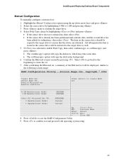
...6HOHFW 0HQX Previous Menu Select Exit First HDD 7. Press to select the drive assignments for the source and target drives, choose the Manual Configuration option. 42 Silicon Image Inc. Creating a Mirrored Set (RAID 1) Automatic Configuration To automatically configure a mirrored set, highlight the...; NOTE The Auto Configuration option will be displayed similar to confirm exit and proceed with operating system setup. Intel Desktop Board D845PEBT2 Product Guide 6. If you wish to exit the RAID Configuration Utility. 8. Press to the following screen image: RAID Configuration ...
...6HOHFW 0HQX Previous Menu Select Exit First HDD 7. Press to select the drive assignments for the source and target drives, choose the Manual Configuration option. 42 Silicon Image Inc. Creating a Mirrored Set (RAID 1) Automatic Configuration To automatically configure a mirrored set, highlight the...; NOTE The Auto Configuration option will be displayed similar to confirm exit and proceed with operating system setup. Intel Desktop Board D845PEBT2 Product Guide 6. If you wish to exit the RAID Configuration Utility. 8. Press to the following screen image: RAID Configuration ...
Product Guide
Page 43
... . • If the source drive already has been partitioned and contains data, and the second drive has been added for redundancy, then select . Highlight the Manual Configuration option using the up-down arrow keys and press . 2. After confirming the Mirrored set, a summary of the Mirrored set will copy the disk in... create RAID set just created by pressing . Press again to confirm exit and proceed with operating system setup. 43 Installing and Replacing Desktop Board Components Manual Configuration To manually configure a mirrored set . 7.
... . • If the source drive already has been partitioned and contains data, and the second drive has been added for redundancy, then select . Highlight the Manual Configuration option using the up-down arrow keys and press . 2. After confirming the Mirrored set, a summary of the Mirrored set will copy the disk in... create RAID set just created by pressing . Press again to confirm exit and proceed with operating system setup. 43 Installing and Replacing Desktop Board Components Manual Configuration To manually configure a mirrored set . 7.

Product Guide
Page 60
... Submenu Feature Plug & Play O/S Numlock Options • No (default) • Yes • Off • On (default) Description Specifies if manual configuration is appropriate when using a Plug and Play operating system. Yes lets the operating system configure Plug & Play (PnP) devices not required for use...to set the Plug & Play options and the power-on the numeric keypad of the Numlock key. Table 14. Intel Desktop Board D845PEBT2 Product Guide Boot Configuration Submenu Maintenance Main Advanced Security Power Boot Exit Boot Configuration The submenu shown in the system. ...
... Submenu Feature Plug & Play O/S Numlock Options • No (default) • Yes • Off • On (default) Description Specifies if manual configuration is appropriate when using a Plug and Play operating system. Yes lets the operating system configure Plug & Play (PnP) devices not required for use...to set the Plug & Play options and the power-on the numeric keypad of the Numlock key. Table 14. Intel Desktop Board D845PEBT2 Product Guide Boot Configuration Submenu Maintenance Main Advanced Security Power Boot Exit Boot Configuration The submenu shown in the system. ...
Product Guide
Page 68
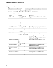
Intel Desktop Board D845PEBT2 Product Guide Chipset Configuration Submenu Maintenance Main Advanced Security Power Boot Exit Chipset Configuration The menu shown in memory. User Defined SDRAM RAS Act. SDRAM ...to be enabled. Selects the number of detected memory frequency value. Allows override of clock cycles between addressing a row and addressing a column. User Defined allows manual override of time required before accessing a new row. 68 Chipset Configuration Submenu Feature Options ISA Enable Bit PCI Latency Timer Extended Configuration SDRAM Frequency SDRAM...
Intel Desktop Board D845PEBT2 Product Guide Chipset Configuration Submenu Maintenance Main Advanced Security Power Boot Exit Chipset Configuration The menu shown in memory. User Defined SDRAM RAS Act. SDRAM ...to be enabled. Selects the number of detected memory frequency value. Allows override of clock cycles between addressing a row and addressing a column. User Defined allows manual override of time required before accessing a new row. 68 Chipset Configuration Submenu Feature Options ISA Enable Bit PCI Latency Timer Extended Configuration SDRAM Frequency SDRAM...


