Product Guide
Page 5
Contents 1 Desktop Board Features Desktop Board Components 11 Processor ...13 Main Memory ...14 Intel® 845GV Chipset ...15 Audio Subsystem ...15 LAN Subsystem (Optional 16 LAN Subsystem Software 16 RJ-45 LAN Connector LEDs 16 Hi...17 Expansion Slots...17 BIOS ...17 PCI Auto Configuration 17 IDE Auto Configuration 17 Security Passwords ...18 Power Management Features 18 Speaker...20 Battery...20 Real-Time Clock...20 2 Installing and Replacing Desktop Board Components Before You Begin ...21 Installation Precautions ...22 Installation Instructions...22 Installing the I/O Shield ...24 ...
Contents 1 Desktop Board Features Desktop Board Components 11 Processor ...13 Main Memory ...14 Intel® 845GV Chipset ...15 Audio Subsystem ...15 LAN Subsystem (Optional 16 LAN Subsystem Software 16 RJ-45 LAN Connector LEDs 16 Hi...17 Expansion Slots...17 BIOS ...17 PCI Auto Configuration 17 IDE Auto Configuration 17 Security Passwords ...18 Power Management Features 18 Speaker...20 Battery...20 Real-Time Clock...20 2 Installing and Replacing Desktop Board Components Before You Begin ...21 Installation Precautions ...22 Installation Instructions...22 Installing the I/O Shield ...24 ...
Product Guide
Page 6
Intel Desktop Board D845GVSR Product Guide Connecting Add-In Card and Peripheral Interface Connectors 36 Setting the BIOS Configuration Jumper Block 37 Clearing Passwords ...38 Back Panel Connectors ...39 Replacing the Battery ...40 3 Updating the BIOS Updating the BIOS with the Intel® Express BIOS Update Utility 45 Updating the BIOS with the Intel... Security Menu ...66 Power Menu ...67 ACPI Submenu...68 Boot Menu...69 Boot Device Priority Submenu 70 Hard Disk Drives Submenu 71 Removable Devices Submenu 72 ATAPI CD-ROM Drives 73 Exit Menu ...74 5 Desktop Board Resources Memory Map ...
Intel Desktop Board D845GVSR Product Guide Connecting Add-In Card and Peripheral Interface Connectors 36 Setting the BIOS Configuration Jumper Block 37 Clearing Passwords ...38 Back Panel Connectors ...39 Replacing the Battery ...40 3 Updating the BIOS Updating the BIOS with the Intel® Express BIOS Update Utility 45 Updating the BIOS with the Intel... Security Menu ...66 Power Menu ...67 ACPI Submenu...68 Boot Menu...69 Boot Device Priority Submenu 70 Hard Disk Drives Submenu 71 Removable Devices Submenu 72 ATAPI CD-ROM Drives 73 Exit Menu ...74 5 Desktop Board Resources Memory Map ...
Product Guide
Page 7
Installing the I/O Shield 24 4. Internal Headers ...31 10. Location of Hardware Control and Power Connectors 34 11. Removing the Battery from the Desktop Board 43 vii Installing a Processor...26 6. Back Panel Connectors 39 14. Desktop Board Mounting Screw Holes 25 5. Connecting the IDE Cable 30 9. Connecting the Processor Fan Heatsink Cable to the Processor Fan Header...
Installing the I/O Shield 24 4. Internal Headers ...31 10. Location of Hardware Control and Power Connectors 34 11. Removing the Battery from the Desktop Board 43 vii Installing a Processor...26 6. Back Panel Connectors 39 14. Desktop Board Mounting Screw Holes 25 5. Connecting the IDE Cable 30 9. Connecting the Processor Fan Heatsink Cable to the Processor Fan Header...
Product Guide
Page 8
...35. Interrupts ...76 37. EMC Regulations ...83 41. Intel Desktop Board D845GVSR Product Guide Tables 1. Processors Supported by the Desktop Board 13 4. BIOS Setup Program Menu Bar 49 11. Event Log Configuration Submenu 61 22. Power Menu...67 27. ACPI Submenu ...68 28. Exit ...32 7. Peripheral Configuration Submenu 55 18. Video Configuration Submenu 62 23. Beep Codes ...77 38. Product Certification Markings 84 viii Desktop Board Components 12 3. USB 2.0 Header (J9F2 33 9. Advanced Menu...52 15. DMA Channels...75 36. Diskette Configuration Submenu 60 21...
...35. Interrupts ...76 37. EMC Regulations ...83 41. Intel Desktop Board D845GVSR Product Guide Tables 1. Processors Supported by the Desktop Board 13 4. BIOS Setup Program Menu Bar 49 11. Event Log Configuration Submenu 61 22. Power Menu...67 27. ACPI Submenu ...68 28. Exit ...32 7. Peripheral Configuration Submenu 55 18. Video Configuration Submenu 62 23. Beep Codes ...77 38. Product Certification Markings 84 viii Desktop Board Components 12 3. USB 2.0 Header (J9F2 33 9. Advanced Menu...52 15. DMA Channels...75 36. Diskette Configuration Submenu 60 21...
Product Guide
Page 9
... support for power, fan, and chassis intrusion connectors, Suspend to RAM, resume on ring, wake from USB and PS/2 keyboard and mouse, and PME# wakeup. 9 Two ports routed to the USB 2.0 header • Two IDE interfaces with DIMMs utilizing 512 Mbit technology DRAM devices Intel® 845GV chipset, consisting of Intel® Desktop Board D845GVSR. Table...
... support for power, fan, and chassis intrusion connectors, Suspend to RAM, resume on ring, wake from USB and PS/2 keyboard and mouse, and PME# wakeup. 9 Two ports routed to the USB 2.0 header • Two IDE interfaces with DIMMs utilizing 512 Mbit technology DRAM devices Intel® 845GV chipset, consisting of Intel® Desktop Board D845GVSR. Table...

Product Guide
Page 12
... M Speaker N Battery O Auxiliary front panel power LED connector P Front chassis fan header Q Chassis intrusion header R BIOS S Front panel header T Front panel USB header U PCI connectors Related Links: Go to the following links for more information about Intel Desktop Board D845GVSR: • http://www.intel.com/design/motherbd • http://support.intel.com/support/motherboards/desktop 12 Intel Desktop Board D845GVSR Product Guide Table 2.
... M Speaker N Battery O Auxiliary front panel power LED connector P Front chassis fan header Q Chassis intrusion header R BIOS S Front panel header T Front panel USB header U PCI connectors Related Links: Go to the following links for more information about Intel Desktop Board D845GVSR: • http://www.intel.com/design/motherbd • http://support.intel.com/support/motherboards/desktop 12 Intel Desktop Board D845GVSR Product Guide Table 2.
Product Guide
Page 13
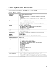
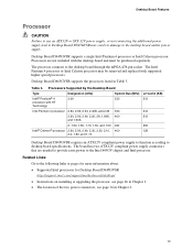
..., and 1.70 Desktop Board D845GVSR requires an ATX12V compliant power supply to function according to the desktop board through the mPGA-478-pin socket. Desktop Board D845GVSR supports a single Intel Pentium 4 processor or Intel Celeron processor. Table 3. Related Links: Go to the following links or pages for more information about: • Supported Intel processors for Desktop Board D845GVSR http://support.intel.com/support/motherboards/desktop/ • Instructions on...
..., and 1.70 Desktop Board D845GVSR requires an ATX12V compliant power supply to function according to the desktop board through the mPGA-478-pin socket. Desktop Board D845GVSR supports a single Intel Pentium 4 processor or Intel Celeron processor. Table 3. Related Links: Go to the following links or pages for more information about: • Supported Intel processors for Desktop Board D845GVSR http://support.intel.com/support/motherboards/desktop/ • Instructions on...
Product Guide
Page 14
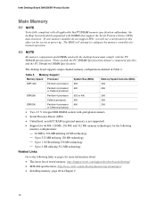
... at power up. Up to 2 GB utilizing 512 MB technology Related Links: Go to the following memory configurations: - 64 MB to configure the memory controller for more information about: • The latest list of tested memory, http://support.intel.com/support/motherboards/desktop/ ...you will attempt to 256 MB utilizing 64 Mb technology - Intel Desktop Board D845GVSR Product Guide Main Memory ✏ NOTE To be fully compliant with all applicable Intel® SDRAM memory specification addendums, the desktop board should be populated with the PC SDRAM specifications. Memory Support ...
... at power up. Up to 2 GB utilizing 512 MB technology Related Links: Go to the following memory configurations: - 64 MB to configure the memory controller for more information about: • The latest list of tested memory, http://support.intel.com/support/motherboards/desktop/ ...you will attempt to 256 MB utilizing 64 Mb technology - Intel Desktop Board D845GVSR Product Guide Main Memory ✏ NOTE To be fully compliant with all applicable Intel® SDRAM memory specification addendums, the desktop board should be populated with the PC SDRAM specifications. Memory Support ...

Product Guide
Page 15
Desktop Board Features Intel® 845GV Chipset The Intel 845GV chipset consists of the following: • Intel 82845GV Graphics and Memory Controller Hub (GMCH) with AHA bus • Intel 82801DB I/O Controller Hub (ICH4) with AHA bus • Firmware Hub (FWH) Related Link: Go to the... subsystem features the following: • Intel 845GV chipset (AC '97) • Realtek ALC202A codec The audio subsystem supports the following link for more information about : • Audio drivers and utilities, http://support.intel.com/support/motherboards/desktop/ • Installing a front panel audio...
Desktop Board Features Intel® 845GV Chipset The Intel 845GV chipset consists of the following: • Intel 82845GV Graphics and Memory Controller Hub (GMCH) with AHA bus • Intel 82801DB I/O Controller Hub (ICH4) with AHA bus • Firmware Hub (FWH) Related Link: Go to the... subsystem features the following: • Intel 845GV chipset (AC '97) • Realtek ALC202A codec The audio subsystem supports the following link for more information about : • Audio drivers and utilities, http://support.intel.com/support/motherboards/desktop/ • Installing a front panel audio...
Product Guide
Page 16
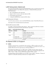
Intel Desktop Board D845GVSR Product Guide LAN Subsystem (Optional) The optional Intel 82562ET (with another computer on Intel's World Wide Web site at USB 1.1 speeds. RJ-45 LAN Connector LEDs LED Color LED State Indicates Green Off 10 Mbit/sec data rate is established. On (steady state) LAN link is selected. The Intel... devices will function normally at : http://support.intel.com/support/motherboards/desktop/ RJ-45 LAN Connector LEDs Two LEDs are ... Table 5 describes the LED states when the desktop board is powered up to accommodate operating systems that meets the ...
Intel Desktop Board D845GVSR Product Guide LAN Subsystem (Optional) The optional Intel 82562ET (with another computer on Intel's World Wide Web site at USB 1.1 speeds. RJ-45 LAN Connector LEDs LED Color LED State Indicates Green Off 10 Mbit/sec data rate is established. On (steady state) LAN link is selected. The Intel... devices will function normally at : http://support.intel.com/support/motherboards/desktop/ RJ-45 LAN Connector LEDs Two LEDs are ... Table 5 describes the LED states when the desktop board is powered up to accommodate operating systems that meets the ...
Product Guide
Page 17
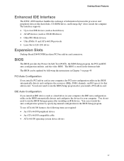
... in card connectors. You do not need to run the BIOS Setup program after you install a PCI add-in card. BIOS The BIOS provides the Power-On Self-Test (POST), the BIOS Setup program, the PCI and IDE auto-configuration utilities, and the video BIOS. To use ATA-66/100 features... CD-ROM drives) • Older PIO Mode devices • Ultra DMA-33 and ATA-66/100 protocols • Laser Servo (LS-120) drives Expansion Slots Desktop Board D845GVSR has three PCI bus add-in the firmware hub. IDE Auto Configuration If you install a PCI add-in card in card. The interface supports: •...
... in card connectors. You do not need to run the BIOS Setup program after you install a PCI add-in card. BIOS The BIOS provides the Power-On Self-Test (POST), the BIOS Setup program, the PCI and IDE auto-configuration utilities, and the video BIOS. To use ATA-66/100 features... CD-ROM drives) • Older PIO Mode devices • Ultra DMA-33 and ATA-66/100 protocols • Laser Servo (LS-120) drives Expansion Slots Desktop Board D845GVSR has three PCI bus add-in the firmware hub. IDE Auto Configuration If you install a PCI add-in card in card. The interface supports: •...
Product Guide
Page 18
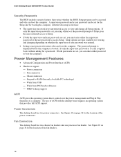
...Chassis intrusion - Wake from PS/2 keyboard/mouse - Power Connectors The desktop board has two power connectors. Fan Connectors The desktop board has two chassis fan headers and one processor fan ...header. See Figure 10 on whether the supervisor or user password was entered. • Setting a user password restricts who can enter either the supervisor password or the user password to RAM (Instantly Available PC technology) - Intel Desktop Board D845GVSR...
...Chassis intrusion - Wake from PS/2 keyboard/mouse - Power Connectors The desktop board has two power connectors. Fan Connectors The desktop board has two chassis fan headers and one processor fan ...header. See Figure 10 on whether the supervisor or user password was entered. • Setting a user password restricts who can enter either the supervisor password or the user password to RAM (Instantly Available PC technology) - Intel Desktop Board D845GVSR...

Product Guide
Page 19
...intel.com/support/motherboards/desktop/ 19 When signaled by a wake-up device or event, the system quickly returns to -RAM) sleep state. Related Links: For more information on standby current requirements, navigate to the TPS by the LED turning amber. The security feature uses a mechanical switch on the desktop board... Instantly Available (ACPI S3 sleep state) configuration. While in memory. Location of Standby Power Indicator OM16273 CAUTION Power supplies used with this desktop board must be able to provide enough standby current to provide adequate standby current when using...
...intel.com/support/motherboards/desktop/ 19 When signaled by a wake-up device or event, the system quickly returns to -RAM) sleep state. Related Links: For more information on standby current requirements, navigate to the TPS by the LED turning amber. The security feature uses a mechanical switch on the desktop board... Instantly Available (ACPI S3 sleep state) configuration. While in memory. Location of Standby Power Indicator OM16273 CAUTION Power supplies used with this desktop board must be able to provide enough standby current to provide adequate standby current when using...
Product Guide
Page 20
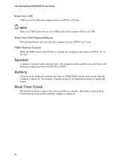
...PCI bus is asserted, the computer wakes from an ACPI S1, S3, or S5 state. NOTE Wake from USB. Real-Time Clock The desktop board has a time-of a USB peripheral that supports Wake from USB requires the use of -day clock and 100-year calendar. The speaker ... Power-On Self-Test (POST). Speaker A speaker is mounted on the desktop board keeps the clock current when the computer is turned off . 20 Battery A battery on the desktop board keeps the values in CMOS RAM and the clock current when the computer is turned off . The battery on the desktop board. Intel Desktop Board D845GVSR ...
...PCI bus is asserted, the computer wakes from an ACPI S1, S3, or S5 state. NOTE Wake from USB. Real-Time Clock The desktop board has a time-of a USB peripheral that supports Wake from USB requires the use of -day clock and 100-year calendar. The speaker ... Power-On Self-Test (POST). Speaker A speaker is mounted on the desktop board keeps the clock current when the computer is turned off . 20 Battery A battery on the desktop board keeps the values in CMOS RAM and the clock current when the computer is turned off . The battery on the desktop board. Intel Desktop Board D845GVSR ...
Product Guide
Page 21
..., such as fans and internal peripherals. Failure to disconnect power, telecommunications links, networks, or modems before performing any procedures can continue to : • Install the I/O shield • Install and remove the desktop board • Install and remove a processor • Install and... remove memory • Connect the IDE cable • Connect internal headers • Connect hardware control and power cables • Connect add-in card and peripheral ...
..., such as fans and internal peripherals. Failure to disconnect power, telecommunications links, networks, or modems before performing any procedures can continue to : • Install the I/O shield • Install and remove the desktop board • Install and remove a processor • Install and... remove memory • Connect the IDE cable • Connect internal headers • Connect hardware control and power cables • Connect add-in card and peripheral ...
Product Guide
Page 22
... damage components. Installation Instructions CAUTION Follow these guidelines to the following when reading the installation instructions for the host chassis, power supply, and other modules or peripherals, as model, serial numbers, installed options, and configuration information. • Electrostatic ... when installing this chapter only at an ESD workstation using an antistatic wrist strap and a conductive foam pad. Intel Desktop Board D845GVSR Product Guide Follow these guidelines before you begin: • Always follow these instructions and the instructions provided by ...
... damage components. Installation Instructions CAUTION Follow these guidelines to the following when reading the installation instructions for the host chassis, power supply, and other modules or peripherals, as model, serial numbers, installed options, and configuration information. • Electrostatic ... when installing this chapter only at an ESD workstation using an antistatic wrist strap and a conductive foam pad. Intel Desktop Board D845GVSR Product Guide Follow these guidelines before you begin: • Always follow these instructions and the instructions provided by ...

Product Guide
Page 23
...certification as denoting compliance with safety requirements. Installing and Replacing Desktop Board Components • Mounting, grounding, and bonding requirements • Keying connectors when mating the wrong connectors could be hazardous If the power supply and other modules or peripherals, as applicable, are... (EMI) requirements. • In Canada A nationally recognized certification mark such as the power supply, peripheral drives, wiring, and cables; are proof of this Desktop Board to be obtained. The Industry Canada statement at the front of certification.
...certification as denoting compliance with safety requirements. Installing and Replacing Desktop Board Components • Mounting, grounding, and bonding requirements • Keying connectors when mating the wrong connectors could be hazardous If the power supply and other modules or peripherals, as applicable, are... (EMI) requirements. • In Canada A nationally recognized certification mark such as the power supply, peripheral drives, wiring, and cables; are proof of this Desktop Board to be obtained. The Industry Canada statement at the front of certification.
Product Guide
Page 25
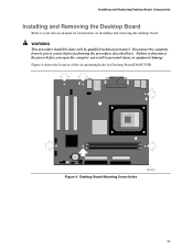
... only by qualified technical personnel. Failure to your chassis manual for Desktop Board D845GVSR. Figure 4. Desktop Board Mounting Screw Holes OM16275 25 Figure 4 shows the location of the six mounting holes for instructions on installing and removing the desktop board. Disconnect the computer from its power source before you open the computer can result in personal injury or...
... only by qualified technical personnel. Failure to your chassis manual for Desktop Board D845GVSR. Figure 4. Desktop Board Mounting Screw Holes OM16275 25 Figure 4 shows the location of the six mounting holes for instructions on installing and removing the desktop board. Disconnect the computer from its power source before you open the computer can result in personal injury or...
Product Guide
Page 26
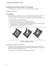
For instructions on page 19). the standby power LED should not be lit (see Figure 5). 4. Observe the precautions in "Before You Begin" on how to install the processor to the Intel World Wide Web site at: http://support.intel.com/support/processors/pentium4/intnotes478.htm 26 Intel Desktop Board D845GVSR Product Guide Installing and Removing a Processor Instructions on...
For instructions on page 19). the standby power LED should not be lit (see Figure 5). 4. Observe the precautions in "Before You Begin" on how to install the processor to the Intel World Wide Web site at: http://support.intel.com/support/processors/pentium4/intnotes478.htm 26 Intel Desktop Board D845GVSR Product Guide Installing and Removing a Processor Instructions on...
Product Guide
Page 28
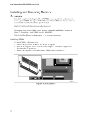
... memory requirements. Turn off the computer and disconnect the AC power cord. 3. Figure 7. Installing DIMMs To install DIMMs, follow these steps: 1. Installing Memory 0 1 OM16277 28 Remove the computer's cover and locate the DIMM sockets (see Figure 7). Observe the precautions in Figure 7. Intel Desktop Board D845GVSR Product Guide Installing and Removing Memory CAUTION To be fully...
... memory requirements. Turn off the computer and disconnect the AC power cord. 3. Figure 7. Installing DIMMs To install DIMMs, follow these steps: 1. Installing Memory 0 1 OM16277 28 Remove the computer's cover and locate the DIMM sockets (see Figure 7). Observe the precautions in Figure 7. Intel Desktop Board D845GVSR Product Guide Installing and Removing Memory CAUTION To be fully...

