
Product Specification
Page 7
...Bus Initialization Checkpoints 81 4.4 Speaker ...82 4.5 BIOS Beep Codes...82 Figures 1. Manufacturing Options 11 3. Supported DDR DIMM Configurations 20 6. Power States and Targeted System Power 34 13. Desktop Board D845GVFN Components 12 2. Location of the Standby Power Indicator LED on the D845GVFN Board 38 4. Video BIOS Video Modes Supported for Front Panel Connector 53 9. System Memory Map 39 16. ATAPI CD-ROM Connector (Optional 49 24. Audio, Power, and Hardware Control Connectors 48 6. Connection Diagram for Front Panel USB Connector 55 10. Location of the Jumper...
...Bus Initialization Checkpoints 81 4.4 Speaker ...82 4.5 BIOS Beep Codes...82 Figures 1. Manufacturing Options 11 3. Supported DDR DIMM Configurations 20 6. Power States and Targeted System Power 34 13. Desktop Board D845GVFN Components 12 2. Location of the Standby Power Indicator LED on the D845GVFN Board 38 4. Video BIOS Video Modes Supported for Front Panel Connector 53 9. System Memory Map 39 16. ATAPI CD-ROM Connector (Optional 49 24. Audio, Power, and Hardware Control Connectors 48 6. Connection Diagram for Front Panel USB Connector 55 10. Location of the Jumper...
Product Specification
Page 8
... 51. Processor Fan Connector 50 27. Main Power Connector 50 28. Front Panel Connector 53 33. Upper Nibble High Byte Functions 81 54. Lower Nibble High Byte Functions 82 55. Intel Desktop Board D845GVFN Technical Product Specification 26. States for a One-Color Power LED 54 34. BIOS Setup Configuration Jumper Settings 57 37. Boot Device Menu Options 72 47. Runtime Code Uncompressed in F000 Shadow RAM 78 52. Auxiliary Front Panel Power/Sleep LED Connector 53 32. Fan Connector Current Capability 60 39. Serial Port B Connector (optional 52 31. Beep Codes...
... 51. Processor Fan Connector 50 27. Main Power Connector 50 28. Front Panel Connector 53 33. Upper Nibble High Byte Functions 81 54. Lower Nibble High Byte Functions 82 55. Intel Desktop Board D845GVFN Technical Product Specification 26. States for a One-Color Power LED 54 34. BIOS Setup Configuration Jumper Settings 57 37. Boot Device Menu Options 72 47. Runtime Code Uncompressed in F000 Shadow RAM 78 52. Auxiliary Front Panel Power/Sleep LED Connector 53 32. Fan Connector Current Capability 60 39. Serial Port B Connector (optional 52 31. Beep Codes...
Product Specification
Page 10
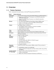
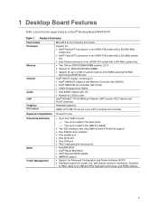
.../2* keyboard and mouse ports • Three fan connectors Expansion Capabilities Three PCI bus add-in card connectors (SMBus routed to PCI bus connector 2) BIOS • Intel/AMI BIOS (resident in an mPGA478 socket with a 400 MHz system bus Memory • Two 184-pin DDR SDRAM Dual Inline Memory Module (DIMM) sockets • Support for single-sided or double-sided DIMMs (DDR333/266/200) • Support for PCI Local Bus Specification Revision 2.2 • Suspend to 2 GB system memory Chipset Video Intel...
.../2* keyboard and mouse ports • Three fan connectors Expansion Capabilities Three PCI bus add-in card connectors (SMBus routed to PCI bus connector 2) BIOS • Intel/AMI BIOS (resident in an mPGA478 socket with a 400 MHz system bus Memory • Two 184-pin DDR SDRAM Dual Inline Memory Module (DIMM) sockets • Support for single-sided or double-sided DIMMs (DDR333/266/200) • Support for PCI Local Bus Specification Revision 2.2 • Suspend to 2 GB system memory Chipset Video Intel...

Product Specification
Page 15
... Description 1.5 Design Specifications Table 3 lists the specifications applicable to the Desktop Board D845GVFN. Revision 3, February 29, 2000, Contact: T13 Chair, Seagate Technology. Specifications Reference Name AC '97 ACPI ASF ATA/ ATAPI-5 ATX ATX12V BIS DDR SDRAM Specification Title Audio Codec '97 Advanced Configuration and Power Interface Specification Alert Standard Format (ASF) Specification Information Technology-AT Attachment with Packet Interface - 5 (ATA/ATAPI-5) ATX Specification ATX/ATX12V Power Supply Design Guide Boot Integrity Services (BIS) Application Programming...
... Description 1.5 Design Specifications Table 3 lists the specifications applicable to the Desktop Board D845GVFN. Revision 3, February 29, 2000, Contact: T13 Chair, Seagate Technology. Specifications Reference Name AC '97 ACPI ASF ATA/ ATAPI-5 ATX ATX12V BIS DDR SDRAM Specification Title Audio Codec '97 Advanced Configuration and Power Interface Specification Alert Standard Format (ASF) Specification Information Technology-AT Attachment with Packet Interface - 5 (ATA/ATAPI-5) ATX Specification ATX/ATX12V Power Supply Design Guide Boot Integrity Services (BIS) Application Programming...

Product Specification
Page 29
.... 1.10.1.2 Auxiliary Line In Connector (Optional) An optional 1 x 4-pin ATAPI-style connector connects the left and right channel signals of an internal audio device to the audio subsystem. Refer to Figure 5, page 48 Table 21, page 49 Section 1.5, page 15 NOTE The front panel audio connector is alternately used as a jumper block for routing audio signals. For information about The location of the connector The signal names of the...
.... 1.10.1.2 Auxiliary Line In Connector (Optional) An optional 1 x 4-pin ATAPI-style connector connects the left and right channel signals of an internal audio device to the audio subsystem. Refer to Figure 5, page 48 Table 21, page 49 Section 1.5, page 15 NOTE The front panel audio connector is alternately used as a jumper block for routing audio signals. For information about The location of the connector The signal names of the...

Product Specification
Page 30
... about Obtaining audio software and drivers Refer to the audio mixer. For information about The location of the ATAPI CD-ROM connector The signal names of the ATAPI CD-ROM connector Refer to the back panel RJ-45 connector with integrated LEDs. Intel Desktop Board D845GVFN Technical Product Specification 1.10.1.3 ATAPI CD-ROM Audio Connector (Optional) An optional 1 x 4-pin ATAPI-style connector connects an internal ATAPI CD-ROM drive to Section 1.3, page 14 1.11 LAN Subsystem (Optional) The Network Interface Controller subsystem...
... about Obtaining audio software and drivers Refer to the audio mixer. For information about The location of the ATAPI CD-ROM connector The signal names of the ATAPI CD-ROM connector Refer to the back panel RJ-45 connector with integrated LEDs. Intel Desktop Board D845GVFN Technical Product Specification 1.10.1.3 ATAPI CD-ROM Audio Connector (Optional) An optional 1 x 4-pin ATAPI-style connector connects an internal ATAPI CD-ROM drive to Section 1.3, page 14 1.11 LAN Subsystem (Optional) The Network Interface Controller subsystem...

Product Specification
Page 45
... line input, ATAPI CD-ROM, and front panel audio) ⎯ Fans ⎯ Power ⎯ Add-in boards (PCI) ⎯ IDE ⎯ Diskette drive ⎯ Chassis intrusion (optional) • External I/O connectors (see page 52) ⎯ Serial Port B (optional) ⎯ Auxiliary front panel power/sleep LED ⎯ Front panel (power/sleep LED, power switch, hard drive activity LED, reset switch, and auxiliary front panel power LED) ⎯ Front panel USB (one connector for two ports) NOTE When installing the board in the load presented by the external devices could cause damage to the...
... line input, ATAPI CD-ROM, and front panel audio) ⎯ Fans ⎯ Power ⎯ Add-in boards (PCI) ⎯ IDE ⎯ Diskette drive ⎯ Chassis intrusion (optional) • External I/O connectors (see page 52) ⎯ Serial Port B (optional) ⎯ Auxiliary front panel power/sleep LED ⎯ Front panel (power/sleep LED, power switch, hard drive activity LED, reset switch, and auxiliary front panel power LED) ⎯ Front panel USB (one connector for two ports) NOTE When installing the board in the load presented by the external devices could cause damage to the...

Product Specification
Page 67
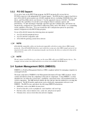
... menu bar is powered-up, the BIOS compares the CPU version and the microcode version in configuration mode. 3 Overview of BIOS and a revision code. The FWH contains the BIOS Setup program, POST, the PCI autoconfiguration utility, and Plug and Play support. The BIOS displays a message during POST identifying the type of BIOS Features What This Chapter Contains 3.1 Introduction ...67 3.2 BIOS Flash Memory Organization 68 3.3 Resource Configuration 68 3.4 System Management BIOS (SMBIOS 69 3.5 Legacy USB Support...70 3.6 BIOS Updates ...70 3.7 Boot Options ...71 3.8 Fast Booting Systems...
... menu bar is powered-up, the BIOS compares the CPU version and the microcode version in configuration mode. 3 Overview of BIOS and a revision code. The FWH contains the BIOS Setup program, POST, the PCI autoconfiguration utility, and Plug and Play support. The BIOS displays a message during POST identifying the type of BIOS Features What This Chapter Contains 3.1 Introduction ...67 3.2 BIOS Flash Memory Organization 68 3.3 Resource Configuration 68 3.4 System Management BIOS (SMBIOS 69 3.5 Legacy USB Support...70 3.6 BIOS Updates ...70 3.7 Boot Options ...71 3.8 Fast Booting Systems...

Product Specification
Page 68
... The Firmware Hub (FWH) includes a 3 Mbit (384 KB) symmetrical flash memory device. 3.3 Resource Configuration 3.3.1 PCI Autoconfiguration The BIOS can automatically configure PCI devices. BIOS Setup Program Menu Bar Maintenance Main Advanced Security Clears passwords and BIS credentials and enables extended configuration mode Allocates resources for hardware components Configures advanced features available through the chipset Sets passwords and security features Power Boot Exit Configures power management features Selects boot options and power supply controls Saves...
... The Firmware Hub (FWH) includes a 3 Mbit (384 KB) symmetrical flash memory device. 3.3 Resource Configuration 3.3.1 PCI Autoconfiguration The BIOS can automatically configure PCI devices. BIOS Setup Program Menu Bar Maintenance Main Advanced Security Clears passwords and BIS credentials and enables extended configuration mode Allocates resources for hardware components Configures advanced features available through the chipset Sets passwords and security features Power Boot Exit Configures power management features Selects boot options and power supply controls Saves...
Product Specification
Page 69
... two PCI IDE connectors with drives using any ATAPI compliant devices, including CD-ROM drives, tape drives, and Ultra DMA drives (see Section 1.5 for the supported version of the drive. To take advantage of the high capacities typically available today, hard drives are backward compatible with independent I/O channel support. NOTE Do not connect an ATA device as event detection and error logging 69 Overview of BIOS Features 3.3.2 PCI IDE Support If you select Auto in a managed network. The BIOS enables...
... two PCI IDE connectors with drives using any ATAPI compliant devices, including CD-ROM drives, tape drives, and Ultra DMA drives (see Section 1.5 for the supported version of the drive. To take advantage of the high capacities typically available today, hard drives are backward compatible with independent I/O channel support. NOTE Do not connect an ATA device as event detection and error logging 69 Overview of BIOS Features 3.3.2 PCI IDE Support If you select Auto in a managed network. The BIOS enables...

Product Specification
Page 77
... control to main BIOS. Do necessary chipset initialization, start memory refresh, and do memory sizing. Give two beeps. If the POST fails, execution stops and the last POST code generated is useful for determining the point where an error occurred. Onboard KBC, RTC enabled (if present). If reading of the POST codes generated by the BIOS. Displaying the POST-codes requires a PCI bus add-in ROM image. To check recovery mode and verify main BIOS checksum. Keyboard controller BAT test, CPU ID...
... control to main BIOS. Do necessary chipset initialization, start memory refresh, and do memory sizing. Give two beeps. If the POST fails, execution stops and the last POST code generated is useful for determining the point where an error occurred. Onboard KBC, RTC enabled (if present). If reading of the POST codes generated by the BIOS. Displaying the POST-codes requires a PCI bus add-in ROM image. To check recovery mode and verify main BIOS checksum. Keyboard controller BAT test, CPU ID...

Product Specification
Page 79
... soft reset. (If power on relocation/shadow. Pattern to enter in base memory. Memory below 1M complete. Memory size display started. Going to be updated during memory test. message displayed. DMA#2 base register test passed. To initialize 8259 interrupt controller. Error Messages and Beep Codes Table 51. Patterns written in real mode. Amount of memory below 1M for lock-key. DMA unit 1 and 2 programming over. Going to clear memory below 1M memory. CPU...
... soft reset. (If power on relocation/shadow. Pattern to enter in base memory. Memory below 1M complete. Memory size display started. Going to be updated during memory test. message displayed. DMA#2 base register test passed. To initialize 8259 interrupt controller. Error Messages and Beep Codes Table 51. Patterns written in real mode. Amount of memory below 1M for lock-key. DMA unit 1 and 2 programming over. Going to clear memory below 1M memory. CPU...

Product Specification
Page 82
... the bus on page 12 4.5 BIOS Beep Codes Whenever a recoverable error occurs during POST, the BIOS displays an error message describing the problem (see Table 55). For information about The location of the onboard speaker on the Desktop Board D845GVFN Refer to initialize the video and writes the error in the upper left corner of short tones. The BIOS also issues a beep code (one long tone followed by two short tones) during POST. An external ROM...
... the bus on page 12 4.5 BIOS Beep Codes Whenever a recoverable error occurs during POST, the BIOS displays an error message describing the problem (see Table 55). For information about The location of the onboard speaker on the Desktop Board D845GVFN Refer to initialize the video and writes the error in the upper left corner of short tones. The BIOS also issues a beep code (one long tone followed by two short tones) during POST. An external ROM...

English Product Guide
Page 3
... to update the BIOS • Desktop Board Resources: information about desktop board resources • Error Messages and Indicators: information about BIOS error messages and beep codes • Regulatory Compliance: safety and EMC regulations, product certification Conventions The following conventions are used in this manual: WARNING Warnings indicate conditions that, if not observed, can cause personal injury. Preface This Product Guide gives information about board layout, component installation, BIOS update...
... to update the BIOS • Desktop Board Resources: information about desktop board resources • Error Messages and Indicators: information about BIOS error messages and beep codes • Regulatory Compliance: safety and EMC regulations, product certification Conventions The following conventions are used in this manual: WARNING Warnings indicate conditions that, if not observed, can cause personal injury. Preface This Product Guide gives information about board layout, component installation, BIOS update...
English Product Guide
Page 6
... IDE Cable 30 8. Location of Fan Headers and Power Connectors 34 10. Intel Desktop Board D845GVFN Product Guide Locating the PCI Bus Add-in Card, Diskette Drive, and IDE Connectors 36 11. Location of the PCI Bus Add-in Card, Diskette Drive, and IDE Connectors 36 Setting the BIOS Configuration Jumper Block 37 Clearing Passwords ...38 Back Panel Connectors...39 Replacing the Battery...40 3 BIOS Using the BIOS Setup Program 45 Updating the BIOS ...45 Updating the BIOS with the Intel® Express BIOS Update Utility 45 Updating the BIOS with the Intel® Iflash BIOS Update Utility...
... IDE Cable 30 8. Location of Fan Headers and Power Connectors 34 10. Intel Desktop Board D845GVFN Product Guide Locating the PCI Bus Add-in Card, Diskette Drive, and IDE Connectors 36 11. Location of the PCI Bus Add-in Card, Diskette Drive, and IDE Connectors 36 Setting the BIOS Configuration Jumper Block 37 Clearing Passwords ...38 Back Panel Connectors...39 Replacing the Battery...40 3 BIOS Using the BIOS Setup Program 45 Updating the BIOS ...45 Updating the BIOS with the Intel® Express BIOS Update Utility 45 Updating the BIOS with the Intel® Iflash BIOS Update Utility...
English Product Guide
Page 9
... and Power Interface (ACPI) • Hardware support for power, fan, and chassis intrusion connectors, Suspend to RAM, wake from USB and PS/2 keyboard and mouse, and PME# wakeup. 9 Feature Summary Form Factor Processor Memory Chipset Audio LAN Graphics I /O controller Expansion Capabilities Three PCI slots Peripheral Interfaces BIOS Power Management • Up to four USB 2.0 ports - Two ports routed to the USB 2.0 header • Two IDE interfaces with DIMMs utilizing 512 Mbit technology DRAM devices Intel® 845GV chipset, consisting of Intel® Desktop Board D845GVFN. Two...
... and Power Interface (ACPI) • Hardware support for power, fan, and chassis intrusion connectors, Suspend to RAM, wake from USB and PS/2 keyboard and mouse, and PME# wakeup. 9 Feature Summary Form Factor Processor Memory Chipset Audio LAN Graphics I /O controller Expansion Capabilities Three PCI slots Peripheral Interfaces BIOS Power Management • Up to four USB 2.0 ports - Two ports routed to the USB 2.0 header • Two IDE interfaces with DIMMs utilizing 512 Mbit technology DRAM devices Intel® 845GV chipset, consisting of Intel® Desktop Board D845GVFN. Two...

English Product Guide
Page 17
... BIOS Setup program can be updated by specifying manual configuration in Chapter 3 on page 45. IDE Auto Configuration If you install a PCI add-in card. If only the supervisor password is booted. Desktop Board Features BIOS The BIOS provides the Power-On Self-Test (POST), the BIOS Setup program, the PCI and IDE auto-configuration utilities, and the video BIOS. The BIOS is set , you install a PCI add-in card in the firmware hub. You do not need to run the BIOS Setup program after installing an IDE device...
... BIOS Setup program can be updated by specifying manual configuration in Chapter 3 on page 45. IDE Auto Configuration If you install a PCI add-in card. If only the supervisor password is booted. Desktop Board Features BIOS The BIOS provides the Power-On Self-Test (POST), the BIOS Setup program, the PCI and IDE auto-configuration utilities, and the video BIOS. The BIOS is set , you install a PCI add-in card in the firmware hub. You do not need to run the BIOS Setup program after installing an IDE device...

English Product Guide
Page 18
... support ACPI ACPI gives the operating system direct control over the power management and Plug and Play functions of the power connectors. Power Connectors The desktop board has two power connectors. See Figure 9 on the front panel, the sleep state is indicated by a wake-up device or event, the system quickly returns to -RAM) sleep state. Intel Desktop Board D845GVFN Product Guide Power Management Features • Advanced Configuration and Power Interface (ACPI) • Hardware support: - Wake from PS/2 keyboard/mouse - Power supplies used with the desktop board...
... support ACPI ACPI gives the operating system direct control over the power management and Plug and Play functions of the power connectors. Power Connectors The desktop board has two power connectors. See Figure 9 on the front panel, the sleep state is indicated by a wake-up device or event, the system quickly returns to -RAM) sleep state. Intel Desktop Board D845GVFN Product Guide Power Management Features • Advanced Configuration and Power Interface (ACPI) • Hardware support: - Wake from PS/2 keyboard/mouse - Power supplies used with the desktop board...

English Product Guide
Page 37
... the jumper settings for booting. 31 Configure (2-3) After the Power-On Self-Test (POST) runs, the BIOS displays the Maintenance Menu. Use this menu to be done in the event of the BIOS configuration jumper block. 31 J9H2 OM16282 Figure 11. Location of the BIOS Configuration Jumper Block The three-pin BIOS jumper block enables all board configurations to clear passwords. 31 Recovery (None) Recovers BIOS from a diskette in BIOS Setup. Jumper Settings for the BIOS Setup Program Modes Jumper Setting 31 Mode Normal (default) (1-2) Description The BIOS uses the current...
... the jumper settings for booting. 31 Configure (2-3) After the Power-On Self-Test (POST) runs, the BIOS displays the Maintenance Menu. Use this menu to be done in the event of the BIOS configuration jumper block. 31 J9H2 OM16282 Figure 11. Location of the BIOS Configuration Jumper Block The three-pin BIOS jumper block enables all board configurations to clear passwords. 31 Recovery (None) Recovers BIOS from a diskette in BIOS Setup. Jumper Settings for the BIOS Setup Program Modes Jumper Setting 31 Mode Normal (default) (1-2) Description The BIOS uses the current...

English Product Guide
Page 52
... connected properly. continued 52 Replace the battery soon. Run Setup to reset values. Intel Desktop Board D845GVFN Product Guide BIOS Error Messages When a recoverable error occurs during read sector from the diskette drive. Run Setup to set correct values. CMOS memory may be updated. Run Setup to protected mode during the memory test. A: Drive Error B: Drive Error No response from corresponding drive. Pri Master HDD Error Pri Slave HDD Error Sec Master HDD Error Sec Slave HDD Error Could not read /write test of DMA controller. BIOS Error...
... connected properly. continued 52 Replace the battery soon. Run Setup to reset values. Intel Desktop Board D845GVFN Product Guide BIOS Error Messages When a recoverable error occurs during read sector from the diskette drive. Run Setup to set correct values. CMOS memory may be updated. Run Setup to protected mode during the memory test. A: Drive Error B: Drive Error No response from corresponding drive. Pri Master HDD Error Pri Slave HDD Error Sec Master HDD Error Sec Slave HDD Error Could not read /write test of DMA controller. BIOS Error...


