Product Specification
Page 5
... 12 1.2.2 Manufacturing Options 13 1.2.3 Board Layouts 14 1.2.4 Block Diagram 16 1.3 Online Support ...17 1.4 Operating System Support 17 1.5 Design Specifications 18 1.6 Processor ...21 1.7 System Memory ...22 1.7.1 Memory Configurations 24 1.8 Intel® 865G Chipset ...29 1.8.1 Intel 865G Graphics Subsystem 30 1.8.2 Universal 0.8 V / 1.5 V AGP 3.0 Connector 38 1.8.3 USB...39 1.8.4 IDE Support 39 1.8.5 Real-Time Clock, CMOS SRAM, and Battery 41...
... 12 1.2.2 Manufacturing Options 13 1.2.3 Board Layouts 14 1.2.4 Block Diagram 16 1.3 Online Support ...17 1.4 Operating System Support 17 1.5 Design Specifications 18 1.6 Processor ...21 1.7 System Memory ...22 1.7.1 Memory Configurations 24 1.8 Intel® 865G Chipset ...29 1.8.1 Intel 865G Graphics Subsystem 30 1.8.2 Universal 0.8 V / 1.5 V AGP 3.0 Connector 38 1.8.3 USB...39 1.8.4 IDE Support 39 1.8.5 Real-Time Clock, CMOS SRAM, and Battery 41...

Product Specification
Page 9
.... BIOS Setup Program Function Keys 106 55. Advanced Menu...108 58. Power States and Targeted System Power 51 17. Auxiliary Line In Connector 72 27. Processor Fan Connector 74 32. Front Panel Connector 80 39. BIOS Setup Configuration Jumper Settings 84 43. Boot Device Menu Options 102 52. PCI Configuration Submenu...
.... BIOS Setup Program Function Keys 106 55. Advanced Menu...108 58. Power States and Targeted System Power 51 17. Auxiliary Line In Connector 72 27. Processor Fan Connector 74 32. Front Panel Connector 80 39. BIOS Setup Configuration Jumper Settings 84 43. Boot Device Menu Options 102 52. PCI Configuration Submenu...
Product Specification
Page 11
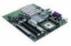
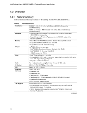
...1.2 Overview ...12 1.3 Online Support ...17 1.4 Operating System Support 17 1.5 Design Specifications 18 1.6 Processor ...21 1.7 System Memory ...22 1.8 Intel® 865G Chipset ...29 1.9 I/O Controller ...41 1.10 Audio Subsystem...43 1.11 LAN Subsystem...46 1.12 ...Hardware Management Subsystem 48 1.13 Power Management 50 1.1 Board Differences This TPS describes these Intel® Desktop Boards: D865GBF and D865GLC. Summary of Board Differences D865GBF • ATX...
...1.2 Overview ...12 1.3 Online Support ...17 1.4 Operating System Support 17 1.5 Design Specifications 18 1.6 Processor ...21 1.7 System Memory ...22 1.8 Intel® 865G Chipset ...29 1.9 I/O Controller ...41 1.10 Audio Subsystem...43 1.11 LAN Subsystem...46 1.12 ...Hardware Management Subsystem 48 1.13 Power Management 50 1.1 Board Differences This TPS describes these Intel® Desktop Boards: D865GBF and D865GLC. Summary of Board Differences D865GBF • ATX...
Product Specification
Page 12
...ATX (11.60 inches by 9.60 inches [294.64 millimeters by 243.84 millimeters]) D865GLC: microATX (9.60 inches by 9.60 inches [243.84 millimeters by 243.84 millimeters]) • Support for an Intel® Pentium® 4 processor in an mPGA478 socket with a 400/533/800...DDR 266 • Support for up to 4 GB of system memory Intel® 865G Chipset, consisting of: • Intel® 82865G Graphics and Memory Controller Hub (GMCH) • Intel® 82801EB I/O Controller Hub (ICH5) • 4 Mbit Firmware Hub (FWH) • Intel® Extreme Graphics 2 controller • Universal 0.8 V / 1.5...
...ATX (11.60 inches by 9.60 inches [294.64 millimeters by 243.84 millimeters]) D865GLC: microATX (9.60 inches by 9.60 inches [243.84 millimeters by 243.84 millimeters]) • Support for an Intel® Pentium® 4 processor in an mPGA478 socket with a 400/533/800...DDR 266 • Support for up to 4 GB of system memory Intel® 865G Chipset, consisting of: • Intel® 82865G Graphics and Memory Controller Hub (GMCH) • Intel® 82801EB I/O Controller Hub (ICH5) • 4 Mbit Firmware Hub (FWH) • Intel® Extreme Graphics 2 controller • Universal 0.8 V / 1.5...
Product Specification
Page 16
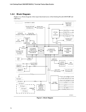
...or socket Parallel ATA IDE Connectors (2) Parallel ATA IDE Interface mPGA478 System Bus Processor Socket (400/533/800 MHz) LAN Connector Gigabit LAN PLC (Optional) CSA Interface AGP Interface Universal 0.8/ 1.5 V AGP 3.0 Connector Intel 82865G Graphics and Memory Controller Hub (GMCH) AHA Bus VGA Port Channel A ... Panel USB Ports Serial Port Parallel Port PS/2 Mouse PS/2 Keyboard Diskette Drive Connector Intel 82801EB I/O Controller Hub (ICH5) Intel 82802AB 4 Mbit Firmware Hub (FWH) Intel 865G Chipset CSMA/CD Unit Interface 10/100 LAN PLC (Optional) LAN Connector AC Link ...
...or socket Parallel ATA IDE Connectors (2) Parallel ATA IDE Interface mPGA478 System Bus Processor Socket (400/533/800 MHz) LAN Connector Gigabit LAN PLC (Optional) CSA Interface AGP Interface Universal 0.8/ 1.5 V AGP 3.0 Connector Intel 82865G Graphics and Memory Controller Hub (GMCH) AHA Bus VGA Port Channel A ... Panel USB Ports Serial Port Parallel Port PS/2 Mouse PS/2 Keyboard Diskette Drive Connector Intel 82801EB I/O Controller Hub (ICH5) Intel 82802AB 4 Mbit Firmware Hub (FWH) Intel 865G Chipset CSMA/CD Unit Interface 10/100 LAN PLC (Optional) LAN Connector AC Link ...
Product Specification
Page 17
...for the Desktop Board D865GLC Processor data sheets ICH5 addressing Custom splash screens Audio software and utilities LAN software and drivers Visit this World Wide Web site: http://www.intel.com/design/motherbd http://support.intel.com/support/motherboards/desktop http://developer.intel.com/design/motherbd/bf/... (with Service Pack 3) and Windows XP (with Service Pack 1) and is not currently supported by any other drivers. 17 Check Intel's Desktop Board website for possible driver updates for other operating systems. • Third party vendors may offer other operating system in the list...
...for the Desktop Board D865GLC Processor data sheets ICH5 addressing Custom splash screens Audio software and utilities LAN software and drivers Visit this World Wide Web site: http://www.intel.com/design/motherbd http://support.intel.com/support/motherboards/desktop http://developer.intel.com/design/motherbd/bf/... (with Service Pack 3) and Windows XP (with Service Pack 1) and is not currently supported by any other drivers. 17 Check Intel's Desktop Board website for possible driver updates for other operating systems. • Third party vendors may offer other operating system in the list...
Product Specification
Page 21
... ATX12V-compliant power supplies with a standard ATX power supply. • Refer to Table 5 on page 22 for a list of ATX12V, SFX12V, and TFX12V power supplies to support the following: • Intel Pentium 4 processors in an mPGA478 processor socket with a 400/533/800 MHz system bus • Intel Celeron processors in an mPGA478 processor socket with a 400 MHz system bus...
... ATX12V-compliant power supplies with a standard ATX power supply. • Refer to Table 5 on page 22 for a list of ATX12V, SFX12V, and TFX12V power supplies to support the following: • Intel Pentium 4 processors in an mPGA478 processor socket with a 400/533/800 MHz system bus • Intel Celeron processors in an mPGA478 processor socket with a 400 MHz system bus...
Product Specification
Page 22
... and program the chipset to Section 1.5, page 18 22 Refer to Section 2.2.1 on the total amount of DIMM... Table 5. Intel Desktop Board D865GBF/D865GLC Technical Product Specification 1.7 System Memory The Desktop Boards D865GBF and D865GLC have four DIMM sockets and support the... supported system bus frequency and memory speed combinations. DDR400 The processor's system bus frequency must be... 800 MHz DDR333 (Note) 800 or 533 MHz DDR266 800, 533, or 400 MHz Note: When using an 800 MHz system bus frequency processor, DDR333 memory is installed, the BIOS will attempt to avoid...
... and program the chipset to Section 1.5, page 18 22 Refer to Section 2.2.1 on the total amount of DIMM... Table 5. Intel Desktop Board D865GBF/D865GLC Technical Product Specification 1.7 System Memory The Desktop Boards D865GBF and D865GLC have four DIMM sockets and support the... supported system bus frequency and memory speed combinations. DDR400 The processor's system bus frequency must be... 800 MHz DDR333 (Note) 800 or 533 MHz DDR266 800, 533, or 400 MHz Note: When using an 800 MHz system bus frequency processor, DDR333 memory is installed, the BIOS will attempt to avoid...
Product Specification
Page 37
... and allows longer in texture loads, 2D blitters, color/Z, MPEG2 motion compression, and other operations. 1.8.1.7 Video Mixing Renderer (VMR) The Intel Extreme Graphics 2 controller features VMR technology. The Intel Pentium 4 processor in the hardware for all graphics surfaces including textures, frame buffer, Z buffer, and video surfaces. Video tearing and corruption is a process where...
... and allows longer in texture loads, 2D blitters, color/Z, MPEG2 motion compression, and other operations. 1.8.1.7 Video Mixing Renderer (VMR) The Intel Extreme Graphics 2 controller features VMR technology. The Intel Pentium 4 processor in the hardware for all graphics surfaces including textures, frame buffer, Z buffer, and video surfaces. Video tearing and corruption is a process where...
Product Specification
Page 39
... on IDE bus allows host and target throttling. The Parallel ATA IDE interfaces support the following modes: • Programmed I/O (PIO): processor controls data transfer. • 8237-style DMA: DMA offloads the processor, supporting transfer rates of up to 16 MB/sec. • Ultra DMA: DMA protocol on IDE bus supporting host and... provides the USB controller for other operating system. and EHCI-compatible drivers. Product Description 1.8.3 USB The boards support up to 88 MB/sec. 39 Check Intel's Desktop Board website for possible driver updates for all ports.
... on IDE bus allows host and target throttling. The Parallel ATA IDE interfaces support the following modes: • Programmed I/O (PIO): processor controls data transfer. • 8237-style DMA: DMA offloads the processor, supporting transfer rates of up to 16 MB/sec. • Ultra DMA: DMA protocol on IDE bus supporting host and... provides the USB controller for other operating system. and EHCI-compatible drivers. Product Description 1.8.3 USB The boards support up to 88 MB/sec. 39 Check Intel's Desktop Board website for possible driver updates for all ports.

Product Specification
Page 48
...control ASIC include: • Internal ambient temperature sensor • Two remote thermal diode sensors for direct monitoring of processor temperature and ambient temperature sensing • Power supply monitoring of the fan connectors and sensors for Management (WfM) ...established. The computer is selected. 1.11.3 LAN Subsystem Software LAN software and drivers are available from Intel's World Wide Web site. LAN link is not established. Intel Desktop Board D865GBF/D865GLC Technical Product Specification Table 14. For information about The location of five voltages (+5...
...control ASIC include: • Internal ambient temperature sensor • Two remote thermal diode sensors for direct monitoring of processor temperature and ambient temperature sensing • Power supply monitoring of the fan connectors and sensors for Management (WfM) ...established. The computer is selected. 1.11.3 LAN Subsystem Software LAN software and drivers are available from Intel's World Wide Web site. LAN link is not established. Intel Desktop Board D865GBF/D865GLC Technical Product Specification Table 14. For information about The location of five voltages (+5...
Product Specification
Page 49
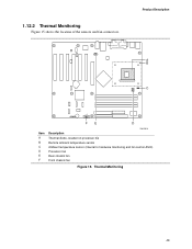
Thermal Monitoring 49 1.12.2 Thermal Monitoring Figure 15 shows the location of the sensors and fan connectors. 31 Product Description A B 1 C 3 13 FE D Item A B C D E F OM15916 Description Thermal diode, located on processor die Remote ambient temperature sensor Ambient temperature sensor (internal to hardware monitoring and fan control ASIC) Processor fan Rear chassis fan Front chassis fan Figure 15.
Thermal Monitoring 49 1.12.2 Thermal Monitoring Figure 15 shows the location of the sensors and fan connectors. 31 Product Description A B 1 C 3 13 FE D Item A B C D E F OM15916 Description Thermal diode, located on processor die Remote ambient temperature sensor Ambient temperature sensor (internal to hardware monitoring and fan control ASIC) Processor fan Rear chassis fan Front chassis fan Figure 15.
Product Specification
Page 51
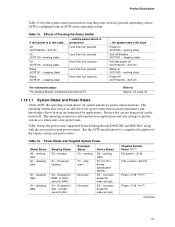
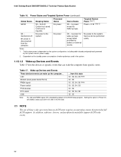
... power except for Off (ACPI G2/G5 - Soft off . sleeping state S4 - Power States and Targeted System Power Global States Sleeping States Processor States Device States G0 - G1 - Processor stopped G1 - stop grant No power D0 - Effects of the various system and power states. working state) More than four seconds On (ACPI...
... power except for Off (ACPI G2/G5 - Soft off . sleeping state S4 - Power States and Targeted System Power Global States Sleeping States Processor States Device States G0 - G1 - Processor stopped G1 - stop grant No power D0 - Effects of the various system and power states. working state) More than four seconds On (ACPI...
Product Specification
Page 52
... supply. 2. No power to the system. Targeted System Power (Note 1) Power < 5 W (Note 2) D3 - Service can wake up logic. Intel Desktop Board D865GBF/D865GLC Technical Product Specification Table 16. Context not saved. Table 17. In addition, software, drivers, and peripherals must fully support ACPI wake... NOTE The use of these wake-up events from an ACPI state requires an operating system that can wake the computer from specific states. Processor States No power No power Device States D3 - LAN Modem (back panel Serial Port A) PME# signal Power switch PS/2 devices RTC...
... supply. 2. No power to the system. Targeted System Power (Note 1) Power < 5 W (Note 2) D3 - Service can wake up logic. Intel Desktop Board D865GBF/D865GLC Technical Product Specification Table 16. Context not saved. Table 17. In addition, software, drivers, and peripherals must fully support ACPI wake... NOTE The use of these wake-up events from an ACPI state requires an operating system that can wake the computer from specific states. Processor States No power No power Device States D3 - LAN Modem (back panel Serial Port A) PME# signal Power switch PS/2 devices RTC...
Product Specification
Page 54
...in the S0 or S1 state. Intel Desktop Board D865GBF/D865GLC Technical Product Specification 1.13.2.2 Fan Connectors Table 18 summarizes the function/operation of providing adequate +5 V standby current. Fan Connector Function/Operation Connector Processor fan Front chassis fan Rear chassis ...fan Description • +12 V DC connection for a processor fan or active fan heatsink. • Fan is off as needed . • ...
...in the S0 or S1 state. Intel Desktop Board D865GBF/D865GLC Technical Product Specification 1.13.2.2 Fan Connectors Table 18 summarizes the function/operation of providing adequate +5 V standby current. Fan Connector Function/Operation Connector Processor fan Front chassis fan Rear chassis ...fan Description • +12 V DC connection for a processor fan or active fan heatsink. • Fan is off as needed . • ...
Product Specification
Page 70
...Internal I/O Connectors The internal I/O connectors are identified as PCI slot #x, starting with respect to the processor. The AGP connector is designed to PCI bus connector 2 only (ATX expansion slot 6). Intel Desktop Board D865GBF/D865GLC Technical Product Specification ✏ NOTE The back panel audio line out connector is ... residing on the Desktop Board. ✏ NOTE This document references back-panel slot numbering with the slot closest to processor location on the Desktop Board D865GLC). Figure 21 (page 76) and Figure 22 (page 77) illustrate the board's PCI slot numbering...
...Internal I/O Connectors The internal I/O connectors are identified as PCI slot #x, starting with respect to the processor. The AGP connector is designed to PCI bus connector 2 only (ATX expansion slot 6). Intel Desktop Board D865GBF/D865GLC Technical Product Specification ✏ NOTE The back panel audio line out connector is ... residing on the Desktop Board. ✏ NOTE This document references back-panel slot numbering with the slot closest to processor location on the Desktop Board D865GLC). Figure 21 (page 76) and Figure 22 (page 77) illustrate the board's PCI slot numbering...
Product Specification
Page 73
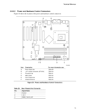
Rear Chassis Fan Connector Pin Signal Name 1 Control 2 +12 V 3 REAR_TACH_OUT 73 Power and Hardware Control Connectors Table 29. Technical Reference 2.8.2.3 Power and Hardware Control Connectors Figure 20 shows the location of the power and hardware control connectors. A B 1 3 12 34 1 3 113 20 11 1 FE D C Item A B C D E F Description Rear chassis fan +12 V power connector (ATX12V) Processor fan Main power Front chassis fan Chassis intrusion For more information see: Table 29 Table 30 Table 31 Table 32 Table 33 Table 34 OM15920 Figure 20.
Rear Chassis Fan Connector Pin Signal Name 1 Control 2 +12 V 3 REAR_TACH_OUT 73 Power and Hardware Control Connectors Table 29. Technical Reference 2.8.2.3 Power and Hardware Control Connectors Figure 20 shows the location of the power and hardware control connectors. A B 1 3 12 34 1 3 113 20 11 1 FE D C Item A B C D E F Description Rear chassis fan +12 V power connector (ATX12V) Processor fan Main power Front chassis fan Chassis intrusion For more information see: Table 29 Table 30 Table 31 Table 32 Table 33 Table 34 OM15920 Figure 20.
Product Specification
Page 74
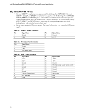
...TFX12V power supplies to the corresponding connectors on /off) 15 Ground 16 Ground 17 Ground 18 No connect 19 +5 V 20 +5 V 74 Processor Fan Connector Pin Signal Name 1 Control 2 +12 V 3 CPU_FAN_TACH Table 32. Use only ATX12V-, SFX12V-, or TFX12V-compliant power supplies with ... 14 PS-ON# (power supply remote on the desktop board, otherwise the board will not boot with a standard ATX power supply. Intel Desktop Board D865GBF/D865GLC Technical Product Specification # INTEGRATOR'S NOTES • Use only ATX12V-compliant power supplies with the Desktop Board D865GLC.
...TFX12V power supplies to the corresponding connectors on /off) 15 Ground 16 Ground 17 Ground 18 No connect 19 +5 V 20 +5 V 74 Processor Fan Connector Pin Signal Name 1 Control 2 +12 V 3 CPU_FAN_TACH Table 32. Use only ATX12V-, SFX12V-, or TFX12V-compliant power supplies with ... 14 PS-ON# (power supply remote on the desktop board, otherwise the board will not boot with a standard ATX power supply. Intel Desktop Board D865GBF/D865GLC Technical Product Specification # INTEGRATOR'S NOTES • Use only ATX12V-compliant power supplies with the Desktop Board D865GLC.

Product Specification
Page 77
... [black] Secondary Parallel ATA IDE [white] SCSI hard drive activity LED (optional) Serial ATA connector 1 Serial ATA connector 0 Figure 22. Do not attempt to the processor). Technical Reference Figure 22 shows the location of the add-in Board and Peripheral Interface Connectors # INTEGRATOR'S NOTES • The AGP connector is not mechanically...
... [black] Secondary Parallel ATA IDE [white] SCSI hard drive activity LED (optional) Serial ATA connector 1 Serial ATA connector 0 Figure 22. Do not attempt to the processor). Technical Reference Figure 22 shows the location of the add-in Board and Peripheral Interface Connectors # INTEGRATOR'S NOTES • The AGP connector is not mechanically...
Product Specification
Page 84
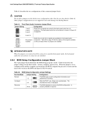
...Audio line out signals are disabled. 2.9.2 BIOS Setup Configuration Jumper Block The 3-pin jumper block determines the BIOS Setup program's mode. Intel Desktop Board D865GBF/D865GLC Technical Product Specification Table 41 describes the two configurations of the signals available on this block in any configuration ... the POST runs, Setup runs automatically. The back panel audio line out connector is powered-up, the BIOS compares the processor version and the microcode version in signals are not supported and could damage the Desktop Board. Table 42 describes the jumper settings for...
...Audio line out signals are disabled. 2.9.2 BIOS Setup Configuration Jumper Block The 3-pin jumper block determines the BIOS Setup program's mode. Intel Desktop Board D865GBF/D865GLC Technical Product Specification Table 41 describes the two configurations of the signals available on this block in any configuration ... the POST runs, Setup runs automatically. The back panel audio line out connector is powered-up, the BIOS compares the processor version and the microcode version in signals are not supported and could damage the Desktop Board. Table 42 describes the jumper settings for...


