Product Specification
Page 7
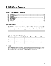
... 4.4.5 Floppy Configuration Submenu 118 4.4.6 Event Log Configuration Submenu 119 4.4.7 Video Configuration Submenu 120 4.4.8 USB Configuration Submenu 121 4.4.9 Chipset Configuration Submenu 122 4.4.10 Fan Control Configuration Submenu 124 4.4.11 Hardware Monitoring 125 4.5 Security Menu ...126 4.6 Power Menu ...127 4.6.1 ACPI Submenu 127 4.7 Boot Menu ...128 4.7.1 Boot Device Priority Submenu 129 4.7.2 Hard Disk Drives Submenu 130 4.7.3 Removable Devices Submenu 130 4.7.4 ATAPI CD-ROM Drives Submenu 131 4.8 Exit Menu ...131 5 Error Messages and Beep Codes 5.1 BIOS Error Messages...
... 4.4.5 Floppy Configuration Submenu 118 4.4.6 Event Log Configuration Submenu 119 4.4.7 Video Configuration Submenu 120 4.4.8 USB Configuration Submenu 121 4.4.9 Chipset Configuration Submenu 122 4.4.10 Fan Control Configuration Submenu 124 4.4.11 Hardware Monitoring 125 4.5 Security Menu ...126 4.6 Power Menu ...127 4.6.1 ACPI Submenu 127 4.7 Boot Menu ...128 4.7.1 Boot Device Priority Submenu 129 4.7.2 Hard Disk Drives Submenu 130 4.7.3 Removable Devices Submenu 130 4.7.4 ATAPI CD-ROM Drives Submenu 131 4.8 Exit Menu ...131 5 Error Messages and Beep Codes 5.1 BIOS Error Messages...
Product Specification
Page 8
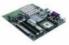
... Power Indicator LED on the D865GBF Board 56 17. Video BIOS Video Modes Supported for S/PDIF Back Panel Connector 44 12. Intel Desktop Board D865GBF/D865GLC Technical Product Specification Figures 1. Desktop Board D865GBF Components 14 2. Memory Channel Configuration 24 5. Examples of the Jumper Blocks 83 27. Flex 6 Audio Subsystem Block Diagram 44 13. LAN Connector LED Locations 46 14. Audio Connectors ...71 20. Power and Hardware Control Connectors 73 21. D865GBF Add-in Board and Peripheral Interface Connectors 77 23. D865GLC Add-in Board...
... Power Indicator LED on the D865GBF Board 56 17. Video BIOS Video Modes Supported for S/PDIF Back Panel Connector 44 12. Intel Desktop Board D865GBF/D865GLC Technical Product Specification Figures 1. Desktop Board D865GBF Components 14 2. Memory Channel Configuration 24 5. Examples of the Jumper Blocks 83 27. Flex 6 Audio Subsystem Block Diagram 44 13. LAN Connector LED Locations 46 14. Audio Connectors ...71 20. Power and Hardware Control Connectors 73 21. D865GBF Add-in Board and Peripheral Interface Connectors 77 23. D865GLC Add-in Board...

Product Specification
Page 9
.... Chassis Intrusion Connector 75 35. Front Panel Connector 80 39. BIOS Setup Configuration Jumper Settings 84 43. Fan Connector Current Capability 88 45. Safety Regulations ...93 49. Boot Configuration Submenu 111 60. LAN Connector LED States 48 15. Auxiliary Line In Connector 72 27. Front Panel Audio Connector/Jumper Block 84 42. Desktop Board D865GBF/D865GLC Environmental Specifications 92 48. Effects of Pressing the Power Switch 51 16. I/O Map ...62 22. PCI Configuration Space Bus Number Options 64 24. Maintenance Menu...
.... Chassis Intrusion Connector 75 35. Front Panel Connector 80 39. BIOS Setup Configuration Jumper Settings 84 43. Fan Connector Current Capability 88 45. Safety Regulations ...93 49. Boot Configuration Submenu 111 60. LAN Connector LED States 48 15. Auxiliary Line In Connector 72 27. Front Panel Audio Connector/Jumper Block 84 42. Desktop Board D865GBF/D865GLC Environmental Specifications 92 48. Effects of Pressing the Power Switch 51 16. I/O Map ...62 22. PCI Configuration Space Bus Number Options 64 24. Maintenance Menu...
Product Specification
Page 13
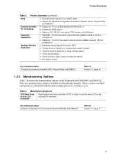
... configurations for PCI Local Bus Specification Revision 2.2 • Suspend to RAM support • Wake on the Desktop Boards D865GBF and D865GLC. Manufacturing Options SCSI Hard Drive Activity LED Connector Allows add-in card connectors (SMBus routed to PCI bus connector 2) Hardware Monitor Subsystem • Hardware monitoring and fan control ASIC • Voltage sense to detect out of range power supply voltages • Thermal sense to detect out of range thermal values • Three fan connectors • Three fan sense inputs used...
... configurations for PCI Local Bus Specification Revision 2.2 • Suspend to RAM support • Wake on the Desktop Boards D865GBF and D865GLC. Manufacturing Options SCSI Hard Drive Activity LED Connector Allows add-in card connectors (SMBus routed to PCI bus connector 2) Hardware Monitor Subsystem • Hardware monitoring and fan control ASIC • Voltage sense to detect out of range power supply voltages • Thermal sense to detect out of range thermal values • Three fan connectors • Three fan sense inputs used...
Product Specification
Page 16
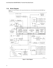
...Bus VGA Port Channel A DIMMs (2) Channel B DIMMs (2) Display Interface Dual-Channel Memory Bus SMBus PCI Bus PCI Slot 1 PCI Slot 2 PCI Slot 3 PCI Slot 4 PCI Slot 5 PCI Slot 6 SMBus D865GBF Only Hardware Monitoring and Fan Control ASIC USB LPC Bus I/O Controller LPC Bus Back Panel/ Front Panel USB Ports Serial Port Parallel Port PS/2 Mouse PS/2 Keyboard Diskette Drive Connector Intel 82801EB I/O Controller Hub (ICH5) Intel 82802AB 4 Mbit Firmware Hub (FWH) Intel 865G Chipset CSMA/CD Unit Interface 10/100 LAN PLC (Optional) LAN Connector AC Link Serial ATA IDE Interface Serial...
...Bus VGA Port Channel A DIMMs (2) Channel B DIMMs (2) Display Interface Dual-Channel Memory Bus SMBus PCI Bus PCI Slot 1 PCI Slot 2 PCI Slot 3 PCI Slot 4 PCI Slot 5 PCI Slot 6 SMBus D865GBF Only Hardware Monitoring and Fan Control ASIC USB LPC Bus I/O Controller LPC Bus Back Panel/ Front Panel USB Ports Serial Port Parallel Port PS/2 Mouse PS/2 Keyboard Diskette Drive Connector Intel 82801EB I/O Controller Hub (ICH5) Intel 82802AB 4 Mbit Firmware Hub (FWH) Intel 865G Chipset CSMA/CD Unit Interface 10/100 LAN PLC (Optional) LAN Connector AC Link Serial ATA IDE Interface Serial...
Product Specification
Page 41
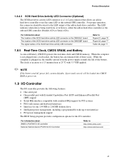
... wake-up event interface • PCI power management support The BIOS Setup program provides configuration options for the I /O Controller Refer to use the same LED as the onboard IDE controller. When the computer is plugged in, the standby current from , or written to, either the add-in hard drive controller to http://www.smsc.com/ http://www.national.com/ 41 Product Description 1.8.4.3 SCSI Hard Drive Activity LED Connector (Optional) The SCSI hard drive activity LED connector is a 1 x 2-pin connector...
... wake-up event interface • PCI power management support The BIOS Setup program provides configuration options for the I /O Controller Refer to use the same LED as the onboard IDE controller. When the computer is plugged in, the standby current from , or written to, either the add-in hard drive controller to http://www.smsc.com/ http://www.national.com/ 41 Product Description 1.8.4.3 SCSI Hard Drive Activity LED Connector (Optional) The SCSI hard drive activity LED connector is a 1 x 2-pin connector...
Product Specification
Page 68
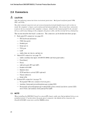
...; PS/2 keyboard and mouse USB (four ports) Parallel port Serial port A VGA port LAN Audio (line out, line in, and mic in) • Internal I/O connectors (see page 70) Audio (auxiliary line input, ATAPI CD-ROM, and front panel audio) Fans [three] Power Add-in boards (PCI and AGP) Parallel ATA IDE Diskette drive SCSI hard drive activity LED (optional) Chassis intrusion Serial ATA...
...; PS/2 keyboard and mouse USB (four ports) Parallel port Serial port A VGA port LAN Audio (line out, line in, and mic in) • Internal I/O connectors (see page 70) Audio (auxiliary line input, ATAPI CD-ROM, and front panel audio) Fans [three] Power Add-in boards (PCI and AGP) Parallel ATA IDE Diskette drive SCSI hard drive activity LED (optional) Chassis intrusion Serial ATA...
Product Specification
Page 76
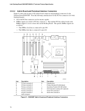
... 3 PCI bus connector 2 PCI bus connector 1 AGP connector Item H I J K L M OM15921 Description Diskette drive Primary Parallel ATA IDE [black] Secondary Parallel ATA IDE [white] SCSI hard drive activity LED (optional) Serial ATA connector 1 Serial ATA connector 0 Figure 21. This enables PCI bus add-in Board and Peripheral Interface Connectors 76 D865GBF Add-in boards with SMBus support to access sensor data on the Desktop Board. Intel Desktop Board D865GBF/D865GLC Technical Product Specification 2.8.2.4 Add-in Board and Peripheral Interface Connectors Figure 21 shows the location of...
... 3 PCI bus connector 2 PCI bus connector 1 AGP connector Item H I J K L M OM15921 Description Diskette drive Primary Parallel ATA IDE [black] Secondary Parallel ATA IDE [white] SCSI hard drive activity LED (optional) Serial ATA connector 1 Serial ATA connector 0 Figure 21. This enables PCI bus add-in Board and Peripheral Interface Connectors 76 D865GBF Add-in boards with SMBus support to access sensor data on the Desktop Board. Intel Desktop Board D865GBF/D865GLC Technical Product Specification 2.8.2.4 Add-in Board and Peripheral Interface Connectors Figure 21 shows the location of...
Product Specification
Page 98
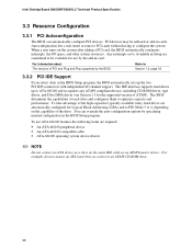
... ATAPI CD-ROM drive. 98 When a user turns on the same IDE cable as a slave to PIO Mode 3 or 4, depending on the capability of ATAPI). To take advantage of each drive and configures them to configure the system. Intel Desktop Board D865GBF/D865GLC Technical Product Specification 3.3 Resource Configuration 3.3.1 PCI Autoconfiguration The BIOS can override the auto-configuration options by specifying manual configuration in the BIOS Setup program. The IDE interface supports hard drives up the two PCI IDE connectors with independent...
... ATAPI CD-ROM drive. 98 When a user turns on the same IDE cable as a slave to PIO Mode 3 or 4, depending on the capability of ATAPI). To take advantage of each drive and configures them to configure the system. Intel Desktop Board D865GBF/D865GLC Technical Product Specification 3.3 Resource Configuration 3.3.1 PCI Autoconfiguration The BIOS can override the auto-configuration options by specifying manual configuration in the BIOS Setup program. The IDE interface supports hard drives up the two PCI IDE connectors with independent...
Product Specification
Page 105
...Desktop Board is in configure mode. 105 Table 53. BIOS Setup Program Menu Bar Maintenance Main Advanced Security Clears passwords and displays processor information Displays processor and memory configuration Configures advanced features available through the chipset Sets passwords and security features Power Boot Configures power management features and power supply controls Selects boot options Exit Saves or discards changes to view and change the BIOS settings for the computer. Maintenance Main Advanced Security Power Boot Exit Table 53 lists the BIOS Setup program menu...
...Desktop Board is in configure mode. 105 Table 53. BIOS Setup Program Menu Bar Maintenance Main Advanced Security Clears passwords and displays processor information Displays processor and memory configuration Configures advanced features available through the chipset Sets passwords and security features Power Boot Configures power management features and power supply controls Selects boot options Exit Saves or discards changes to view and change the BIOS settings for the computer. Maintenance Main Advanced Security Power Boot Exit Table 53 lists the BIOS Setup program menu...
Product Specification
Page 106
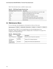
... Main Advanced Security Power Boot Exit The menu shown in configure mode. Displays CPU's Microcode Update Revision. 106 Setup only displays this menu in Table 55 is for the current menu Save the current values and exits the BIOS Setup program Exits the menu 4.2 Maintenance Menu To access this menu, select Maintenance on page 84 for menu screens. Displays CPU's Stepping Signature. Maintenance Menu Feature Options Clear All Passwords CPU Stepping Signature • Ok (default) • Cancel No options CPU Microcode Update...
... Main Advanced Security Power Boot Exit The menu shown in configure mode. Displays CPU's Microcode Update Revision. 106 Setup only displays this menu in Table 55 is for the current menu Save the current values and exits the BIOS Setup program Exits the menu 4.2 Maintenance Menu To access this menu, select Maintenance on page 84 for menu screens. Displays CPU's Stepping Signature. Maintenance Menu Feature Options Clear All Passwords CPU Stepping Signature • Ok (default) • Cancel No options CPU Microcode Update...
Product Specification
Page 113
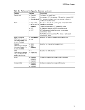
... another device. • Output Only Selects the mode for the parallel port. BIOS Setup Program Table 60. ECP is Enhanced Capabilities Port mode, a high-speed bi-directional mode. • 378 (default) Specifies the base I /O address (This feature is present only when Parallel Port is set to Enabled) Interrupt (This feature is present only when Parallel Port is set to ECP) Audio Onboard LAN Options Description • Disabled Configures the parallel port. • Enabled Auto assigns...
... another device. • Output Only Selects the mode for the parallel port. BIOS Setup Program Table 60. ECP is Enhanced Capabilities Port mode, a high-speed bi-directional mode. • 378 (default) Specifies the base I /O address (This feature is present only when Parallel Port is set to Enabled) Interrupt (This feature is present only when Parallel Port is set to ECP) Audio Onboard LAN Options Description • Disabled Configures the parallel port. • Enabled Auto assigns...
Product Specification
Page 117
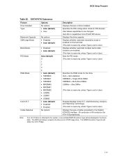
...; UDMA0 • UDMA1 • UDMA2 • Auto (default) • Disabled • Enabled No options Description Displays the type of cable connected to User.) Specifies the DMA mode for ATA-100 peripherals). Auto fills-in the above table. Displays whether automatic translation mode is set to User.) Displays the type of drive installed. Specifies the IDE configuration mode for the hard disk. (This item is read-only unless Type is set to User.) Displays whether automatic multiple sector data transfers...
...; UDMA0 • UDMA1 • UDMA2 • Auto (default) • Disabled • Enabled No options Description Displays the type of cable connected to User.) Specifies the DMA mode for ATA-100 peripherals). Auto fills-in the above table. Displays whether automatic translation mode is set to User.) Displays the type of drive installed. Specifies the IDE configuration mode for the hard disk. (This item is read-only unless Type is set to User.) Displays whether automatic multiple sector data transfers...
Product Specification
Page 118
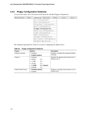
...189;" • Disabled (default) • Enabled Description Disables or enables the integrated diskette controller. Intel Desktop Board D865GBF/D865GLC Technical Product Specification 4.4.5 Floppy Configuration Submenu To access this menu, select Advanced on the menu bar and then Floppy Configuration. Maintenance Main Advanced Security Power PCI Configuration Boot Configuration Peripheral Configuration Drive Configuration Floppy Configuration Event Log Configuration Video Configuration USB Configuration Chipset Configuration Fan Control Configuration Hardware Monitoring Boot Exit The...
...189;" • Disabled (default) • Enabled Description Disables or enables the integrated diskette controller. Intel Desktop Board D865GBF/D865GLC Technical Product Specification 4.4.5 Floppy Configuration Submenu To access this menu, select Advanced on the menu bar and then Floppy Configuration. Maintenance Main Advanced Security Power PCI Configuration Boot Configuration Peripheral Configuration Drive Configuration Floppy Configuration Event Log Configuration Video Configuration USB Configuration Chipset Configuration Fan Control Configuration Hardware Monitoring Boot Exit The...
Product Specification
Page 123
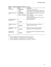
.... Aggressive = Selects most aggressive user-defined timings. This option is displayed only if the installed processor has an 800 MHz system bus. 4. User Defined. 123 Corresponds to the memory detected. This feature is displayed only if SDRAM Timing Control is set to CAS# Delay (Note 4) SDRAM RAS# Precharge (Note 4) Options • Auto (default) • Enabled • Disabled • Auto (default) • Manual - Aggressive • Manual - Manual - Notes: 1. Chipset Configuration Submenu (continued) Feature CPC Override...
.... Aggressive = Selects most aggressive user-defined timings. This option is displayed only if the installed processor has an 800 MHz system bus. 4. User Defined. 123 Corresponds to the memory detected. This feature is displayed only if SDRAM Timing Control is set to CAS# Delay (Note 4) SDRAM RAS# Precharge (Note 4) Options • Auto (default) • Enabled • Disabled • Auto (default) • Manual - Aggressive • Manual - Manual - Notes: 1. Chipset Configuration Submenu (continued) Feature CPC Override...

Product Specification
Page 124
...Fan Control Configuration Submenu Feature Fan Control Lowest Fan Speed Options • Disabled • Enabled (default) • Slow (default) • Off Description Enables or disables fan control. Maintenance Main Advanced Security Power PCI Configuration Boot Configuration Peripheral Configuration Drive Configuration Floppy Configuration Event Log Configuration Video Configuration USB Configuration Chipset Configuration Fan Control Configuration Hardware Monitoring Boot Exit The submenu represented in Table 68 is for configuring fan control options. Table 68. When set...
...Fan Control Configuration Submenu Feature Fan Control Lowest Fan Speed Options • Disabled • Enabled (default) • Slow (default) • Off Description Enables or disables fan control. Maintenance Main Advanced Security Power PCI Configuration Boot Configuration Peripheral Configuration Drive Configuration Floppy Configuration Event Log Configuration Video Configuration USB Configuration Chipset Configuration Fan Control Configuration Hardware Monitoring Boot Exit The submenu represented in Table 68 is for configuring fan control options. Table 68. When set...

Product Specification
Page 128
... drives. Maintenance Main Advanced Security Power Boot Exit Boot Device Priority Hard Disk Drives Removable Devices ATAPI CD-ROM Drives The menu represented in the Boot Device menu. Table 73. Specifies the boot sequence from the menu bar at the top of the screen. Intel Desktop Board D865GBF/D865GLC Technical Product Specification 4.7 Boot Menu To access this menu, select Boot from the available removable devices. Enables the computer to set to Enabled, you must reboot for the Intel Boot Agent device to display submenu Description Disabled displays normal POST...
... drives. Maintenance Main Advanced Security Power Boot Exit Boot Device Priority Hard Disk Drives Removable Devices ATAPI CD-ROM Drives The menu represented in the Boot Device menu. Table 73. Specifies the boot sequence from the menu bar at the top of the screen. Intel Desktop Board D865GBF/D865GLC Technical Product Specification 4.7 Boot Menu To access this menu, select Boot from the available removable devices. Enables the computer to set to Enabled, you must reboot for the Intel Boot Agent device to display submenu Description Disabled displays normal POST...
Product Specification
Page 135
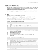
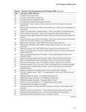
... BIOS. EF Booting from floppy. Displaying the POST-codes requires a PCI bus add-in ROM image. Copy main BIOS image to F000 shadow RAM and give control to more than one operation. If either it is recovery mode or main BIOS checksum is bad, go to check point E0 for ATAPI (LS-120, Zip) devices. Do necessary chipset initialization, start memory refresh, and do memory sizing. Some codes are repeated in segment 0. E9 Initialize floppy drive...
... BIOS. EF Booting from floppy. Displaying the POST-codes requires a PCI bus add-in ROM image. Copy main BIOS image to F000 shadow RAM and give control to more than one operation. If either it is recovery mode or main BIOS checksum is bad, go to check point E0 for ATAPI (LS-120, Zip) devices. Do necessary chipset initialization, start memory refresh, and do memory sizing. Some codes are repeated in segment 0. E9 Initialize floppy drive...
Product Specification
Page 137
... address line, parity/NMI disable successful. Pattern to find out amount of POST Operation To prepare the descriptor tables. Going to be updated during memory test. Going to enter in real mode. 54 Shutdown successful, CPU in extended memory. Going to find out amount of memory below 1M found . Going to issue keyboard reset command. 81 Keyboard reset error/stuck key found and verified. To...
... address line, parity/NMI disable successful. Pattern to find out amount of POST Operation To prepare the descriptor tables. Going to be updated during memory test. Going to enter in real mode. 54 Shutdown successful, CPU in extended memory. Going to find out amount of memory below 1M found . Going to issue keyboard reset command. 81 Keyboard reset error/stuck key found and verified. To...
Product Specification
Page 140
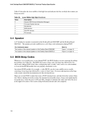
... onboard speaker on the Desktop Board D865GBF The location of the onboard speaker on the Desktop Board D865GLC Refer to zero. The BIOS also issues a beep code (one long tone followed by two short tones) during POST if the video configuration fails (a faulty video card or no card installed) or if an external ROM module does not properly checksum to Figure 1, on page 14 Figure 2, on page 15 5.5 BIOS Beep Codes Whenever a recoverable error occurs during POST...
... onboard speaker on the Desktop Board D865GBF The location of the onboard speaker on the Desktop Board D865GLC Refer to zero. The BIOS also issues a beep code (one long tone followed by two short tones) during POST if the video configuration fails (a faulty video card or no card installed) or if an external ROM module does not properly checksum to Figure 1, on page 14 Figure 2, on page 15 5.5 BIOS Beep Codes Whenever a recoverable error occurs during POST...


