
Product Specification
Page 5
...Online Support 15 1.4 Processor 15 1.5 System Memory 16 1.5.1 Memory Configurations 17 1.6 Intel® Q35 Express Chipset 19 1.6.1 Intel Q35 Graphics Subsystem 19 1.6.2 USB 21 1.6.3 Serial ATA Interfaces 21 1.7 Parallel IDE Controller 22 1.8 Real-Time Clock Subsystem 23 1.9 Legacy I/O Controller 23 1.9.1 Serial Port 23 1.10 Audio Subsystem 24 1.10.1 Audio Subsystem Software 24 1.10.2 Audio Connectors and Headers 25 1.11 LAN Subsystem 26 1.11.1 Intel® 82566DM-2 Gigabit Ethernet Controller 26 1.11.2 LAN Subsystem Software 27 1.11.3 RJ-45 LAN Connector with Integrated LEDs...
...Online Support 15 1.4 Processor 15 1.5 System Memory 16 1.5.1 Memory Configurations 17 1.6 Intel® Q35 Express Chipset 19 1.6.1 Intel Q35 Graphics Subsystem 19 1.6.2 USB 21 1.6.3 Serial ATA Interfaces 21 1.7 Parallel IDE Controller 22 1.8 Real-Time Clock Subsystem 23 1.9 Legacy I/O Controller 23 1.9.1 Serial Port 23 1.10 Audio Subsystem 24 1.10.1 Audio Subsystem Software 24 1.10.2 Audio Connectors and Headers 25 1.11 LAN Subsystem 26 1.11.1 Intel® 82566DM-2 Gigabit Ethernet Controller 26 1.11.2 LAN Subsystem Software 27 1.11.3 RJ-45 LAN Connector with Integrated LEDs...

Product Specification
Page 6
... 3.5 Legacy USB Support 62 3.6 BIOS Updates 62 3.6.1 Language Support 63 3.6.2 Custom Splash Screen 63 3.7 BIOS Recovery 63 3.8 Boot Options 64 3.8.1 CD-ROM Boot 64 3.8.2 Network Boot 64 3.8.3 Booting Without Attached Devices 64 3.8.4 Changing the Default Boot Device During POST 64 3.9 Adjusting Boot Speed 65 3.9.1 Peripheral Selection and Configuration 65 3.9.2 BIOS Boot Optimizations 65 3.10 BIOS Security Features 66 4 Error Messages and Beep Codes 4.1 Speaker 67 4.2 BIOS Beep Codes 67 4.3 BIOS Error Messages 67 4.4 Port 80h POST Codes 68 5 Regulatory Compliance and Battery...
... 3.5 Legacy USB Support 62 3.6 BIOS Updates 62 3.6.1 Language Support 63 3.6.2 Custom Splash Screen 63 3.7 BIOS Recovery 63 3.8 Boot Options 64 3.8.1 CD-ROM Boot 64 3.8.2 Network Boot 64 3.8.3 Booting Without Attached Devices 64 3.8.4 Changing the Default Boot Device During POST 64 3.9 Adjusting Boot Speed 65 3.9.1 Peripheral Selection and Configuration 65 3.9.2 BIOS Boot Optimizations 65 3.10 BIOS Security Features 66 4 Error Messages and Beep Codes 4.1 Speaker 67 4.2 BIOS Beep Codes 67 4.3 BIOS Error Messages 67 4.4 Port 80h POST Codes 68 5 Regulatory Compliance and Battery...
Product Specification
Page 7
... 10 2. Intel AMT states 37 11. Auxiliary Front Panel Power/Sleep LED Header 49 21. Detailed System Memory Address Map 42 10. Component-side Connectors and Headers 45 12. Audio Jack Retasking Support 24 6. HD Audio Link Header 47 14. Serial Port Header 47 17. Processor Core Power Connector 49 22. Back Panel Audio Connector Options 25 5. Location of Pressing the Power Switch 32 8. Localized High Temperature Zones 57 Tables 1. Board Components Shown in Figure 11 46 13. Wake-up Devices and...
... 10 2. Intel AMT states 37 11. Auxiliary Front Panel Power/Sleep LED Header 49 21. Detailed System Memory Address Map 42 10. Component-side Connectors and Headers 45 12. Audio Jack Retasking Support 24 6. HD Audio Link Header 47 14. Serial Port Header 47 17. Processor Core Power Connector 49 22. Back Panel Audio Connector Options 25 5. Location of Pressing the Power Switch 32 8. Localized High Temperature Zones 57 Tables 1. Board Components Shown in Figure 11 46 13. Wake-up Devices and...
Product Specification
Page 8
... 79 44. BIOS Setup Configuration Jumper Settings 53 27. Product Certification Markings 80 viii Boot Device Menu Options 64 35. Lead-Free Board Markings 78 43. Beep Codes 67 37. Acceptable Drives/Media Types for a One-Color Power LED 51 25. Port 80h POST Code Ranges 68 39. Intel Desktop Board DQ35JO Technical Product Specification 23. BIOS Setup Program Menu Bar 60 32. Typical Port 80h POST Sequence 72 41. States for Components 58 30. Supervisor and User Password Functions 66...
... 79 44. BIOS Setup Configuration Jumper Settings 53 27. Product Certification Markings 80 viii Boot Device Menu Options 64 35. Lead-Free Board Markings 78 43. Beep Codes 67 37. Acceptable Drives/Media Types for a One-Color Power LED 51 25. Port 80h POST Code Ranges 68 39. Intel Desktop Board DQ35JO Technical Product Specification 23. BIOS Setup Program Menu Bar 60 32. Typical Port 80h POST Sequence 72 41. States for Components 58 30. Supervisor and User Password Functions 66...
Product Specification
Page 10
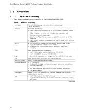
... memory using DDR2 800 or DDR2 667 DIMMs Intel® Q35 Express Chipset, consisting of the Desktop Board DQ35JO. Intel Desktop Board DQ35JO Technical Product Specification 1.1 Overview 1.1.1 Feature Summary Table 1 summarizes the major features of : • Intel® 82Q35 Graphics and Memory Controller Hub (GMCH) • Intel® 82801IDO I/O Controller Hub (ICH9DO) Audio Video 4-channel (2+2) audio subsystem using the RealTek* ALC268-GR audio codec Intel® Graphics Media Accelerator 3100 graphics controller Legacy I/O Control Peripheral Interfaces LAN Support BIOS Legacy...
... memory using DDR2 800 or DDR2 667 DIMMs Intel® Q35 Express Chipset, consisting of the Desktop Board DQ35JO. Intel Desktop Board DQ35JO Technical Product Specification 1.1 Overview 1.1.1 Feature Summary Table 1 summarizes the major features of : • Intel® 82Q35 Graphics and Memory Controller Hub (GMCH) • Intel® 82801IDO I/O Controller Hub (ICH9DO) Audio Video 4-channel (2+2) audio subsystem using the RealTek* ALC268-GR audio codec Intel® Graphics Media Accelerator 3100 graphics controller Legacy I/O Control Peripheral Interfaces LAN Support BIOS Legacy...

Product Specification
Page 15
... MHz, or 800 MHz system bus • Intel Pentium Dual-Core processor in an LGA775 socket with an 800 MHz system bus • Intel Celeron processor 400 sequence in the future. Intel® Desktop Board DQ35JO Desktop Board Support Available configurations for mouse and keyboard • No serial port on the back panel • The serial port header is designed to support processors with an 800 MHz system bus Other processors may require a specialized chassis or cabling solution to use 1.3 Online Support To find...
... MHz, or 800 MHz system bus • Intel Pentium Dual-Core processor in an LGA775 socket with an 800 MHz system bus • Intel Celeron processor 400 sequence in the future. Intel® Desktop Board DQ35JO Desktop Board Support Available configurations for mouse and keyboard • No serial port on the back panel • The serial port header is designed to support processors with an 800 MHz system bus Other processors may require a specialized chassis or cabling solution to use 1.3 Online Support To find...

Product Specification
Page 17
... mode. Memory Configuration Examples Refer to : http://support.intel.com/support/motherboards/desktop/sb/CS025414.htm 1.5.1 Memory Configurations The Intel 82Q35 GMCH supports the following types of memory organization: • Dual channel (Interleaved) mode. Dual channel mode is installed or the memory capacities are used between channels, the slowest memory timing will be equal. Technology and device width can vary from one x8 Double-sided DIMM) DDR2 667 512 Mbit 256 MB 1 GB DDR2 667 1 Gbit 512 MB 2 GB DDR2 800...
... mode. Memory Configuration Examples Refer to : http://support.intel.com/support/motherboards/desktop/sb/CS025414.htm 1.5.1 Memory Configurations The Intel 82Q35 GMCH supports the following types of memory organization: • Dual channel (Interleaved) mode. Dual channel mode is installed or the memory capacities are used between channels, the slowest memory timing will be equal. Technology and device width can vary from one x8 Double-sided DIMM) DDR2 667 512 Mbit 256 MB 1 GB DDR2 667 1 Gbit 512 MB 2 GB DDR2 800...
Product Specification
Page 20
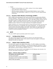
... legacy applications. An example of system memory can be when using VGA graphics under DOS. Up to 287 MB of this board are assumed. 1.6.1.4 Digital Video Interface (DVI) The DVI-D port supports only digital video output. DVI Port Status Conditions PCI Express x16 connector status No add-in card installed Non-video PCI Express x1 add-in card installed PCI Express x4, x8, or x16 add-in Table 4. Intel Desktop Board DQ35JO Technical Product Specification • Display ⎯ Supports...
... legacy applications. An example of system memory can be when using VGA graphics under DOS. Up to 287 MB of this board are assumed. 1.6.1.4 Digital Video Interface (DVI) The DVI-D port supports only digital video output. DVI Port Status Conditions PCI Express x16 connector status No add-in card installed Non-video PCI Express x1 add-in card installed PCI Express x4, x8, or x16 add-in Table 4. Intel Desktop Board DQ35JO Technical Product Specification • Display ⎯ Supports...

Product Specification
Page 22
.... The Parallel ATA IDE interface also supports ATAPI devices (such as CD-ROM drives) and ATA devices. Intel Desktop Board DQ35JO Technical Product Specification NOTE Many Serial ATA drives use new low-voltage power connectors and require adapters or power supplies equipped with low-voltage power connectors. For information about The location of the Serial ATA connectors Refer to Figure 11, page 45 1.6.3.2 Serial ATA RAID The DQ35JO Desktop Board supports the following modes: • Programmed I/O (PIO): processor controls data transfer. •...
.... The Parallel ATA IDE interface also supports ATAPI devices (such as CD-ROM drives) and ATA devices. Intel Desktop Board DQ35JO Technical Product Specification NOTE Many Serial ATA drives use new low-voltage power connectors and require adapters or power supplies equipped with low-voltage power connectors. For information about The location of the Serial ATA connectors Refer to Figure 11, page 45 1.6.3.2 Serial ATA RAID The DQ35JO Desktop Board supports the following modes: • Programmed I/O (PIO): processor controls data transfer. •...

Product Specification
Page 26
... LAN connector with integrated status LEDs Additional features of the LAN subsystem include: • CSMA/CD protocol engine • LAN connect interface between ICH9DO and the LAN controller • PCI Conventional bus power management ⎯ ACPI technology support ⎯ LAN wake capabilities • LAN subsystem software For information about LAN software and drivers Refer to http://downloadcenter.intel.com 1.11.1 Intel® 82566DM-2 Gigabit Ethernet Controller The Intel 82566DM-2 Gigabit Ethernet Controller supports the following features: • Intel...
... LAN connector with integrated status LEDs Additional features of the LAN subsystem include: • CSMA/CD protocol engine • LAN connect interface between ICH9DO and the LAN controller • PCI Conventional bus power management ⎯ ACPI technology support ⎯ LAN wake capabilities • LAN subsystem software For information about LAN software and drivers Refer to http://downloadcenter.intel.com 1.11.1 Intel® 82566DM-2 Gigabit Ethernet Controller The Intel 82566DM-2 Gigabit Ethernet Controller supports the following features: • Intel...
Product Specification
Page 42
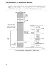
...-in cards and BIOS settings. Intel Desktop Board DQ35JO Technical Product Specification The amount of installed memory that can be used when there is no overlap of system addresses. 8 GB Top of System Address Space FLASH APIC Reserved Upper 4 GB of address space ~20 MB PCI Memory Range contains PCI, chipsets, Direct Media Interface (DMI), and ICH ranges (approximately 750 MB) DRAM Range DOS Compatibility Memory Top of...
...-in cards and BIOS settings. Intel Desktop Board DQ35JO Technical Product Specification The amount of installed memory that can be used when there is no overlap of system addresses. 8 GB Top of System Address Space FLASH APIC Reserved Upper 4 GB of address space ~20 MB PCI Memory Range contains PCI, chipsets, Direct Media Interface (DMI), and ICH ranges (approximately 750 MB) DRAM Range DOS Compatibility Memory Top of...

Product Specification
Page 52
... the IEEE 1394a header. # INTEGRATOR'S NOTES • The +12 V DC power on the USB headers is fused. • The IEEE 1394a header provides one IEEE 1394a port. Intel Desktop Board DQ35JO Technical Product Specification 2.2.2.6 Front Panel USB Headers Figure 13 is a connection diagram for the front panel USB headers. # INTEGRATOR'S NOTES • The +5 V DC power on the IEEE 1394a header is fused. • Use only a front panel USB connector that conforms to the USB 2.0 specification for high-speed USB devices.
... the IEEE 1394a header. # INTEGRATOR'S NOTES • The +12 V DC power on the USB headers is fused. • The IEEE 1394a header provides one IEEE 1394a port. Intel Desktop Board DQ35JO Technical Product Specification 2.2.2.6 Front Panel USB Headers Figure 13 is a connection diagram for the front panel USB headers. # INTEGRATOR'S NOTES • The +5 V DC power on the IEEE 1394a header is fused. • Use only a front panel USB connector that conforms to the USB 2.0 specification for high-speed USB devices.

Product Specification
Page 59
...configure mode. 59 The SPI Flash contains the BIOS Setup program, POST, the PCI auto-configuration utility, LAN EEPROM information, and Plug and Play support. The BIOS displays a message during POST identifying the type of BIOS Features What This Chapter Contains 3.1 Introduction 59 3.2 BIOS Flash Memory Organization 60 3.3 Resource Configuration 60 3.4 System Management BIOS (SMBIOS 61 3.5 Legacy USB Support 62 3.6 BIOS Updates 62 3.7 BIOS Recovery 63 3.8 Boot Options 64 3.9 Adjusting Boot Speed 65 3.10 BIOS Security Features 66 3.1 Introduction The board uses an Intel BIOS...
...configure mode. 59 The SPI Flash contains the BIOS Setup program, POST, the PCI auto-configuration utility, LAN EEPROM information, and Plug and Play support. The BIOS displays a message during POST identifying the type of BIOS Features What This Chapter Contains 3.1 Introduction 59 3.2 BIOS Flash Memory Organization 60 3.3 Resource Configuration 60 3.4 System Management BIOS (SMBIOS 61 3.5 Legacy USB Support 62 3.6 BIOS Updates 62 3.7 BIOS Recovery 63 3.8 Boot Options 64 3.9 Adjusting Boot Speed 65 3.10 BIOS Security Features 66 3.1 Introduction The board uses an Intel BIOS...

Product Specification
Page 60
... configure PCI devices. When a user turns on the system after adding a PCI card, the BIOS automatically configures interrupts, the I/O space, and other system resources. Table 32. Intel Desktop Board DQ35JO Technical Product Specification Table 31 lists the BIOS Setup program menu features. Table 31. BIOS Setup Program Menu Bar Maintenance Clears passwords and displays processor information Main Advanced Security Displays processor and memory configuretion Configures advanced features available through the chipset Sets passwords and security features Power Configures power...
... configure PCI devices. When a user turns on the system after adding a PCI card, the BIOS automatically configures interrupts, the I/O space, and other system resources. Table 32. Intel Desktop Board DQ35JO Technical Product Specification Table 31 lists the BIOS Setup program menu features. Table 31. BIOS Setup Program Menu Bar Maintenance Clears passwords and displays processor information Main Advanced Security Displays processor and memory configuretion Configures advanced features available through the chipset Sets passwords and security features Power Configures power...

Product Specification
Page 61
... main component of SMBIOS is a Desktop Management Interface (DMI) compliant method for obtaining the SMBIOS information. The IDE interface supports hard drives up the PCI IDE connector with independent I/O channel support. For example, do not connect an ATA hard drive as a slave to PIO Mode 3 or 4, depending on the same IDE cable as an ATAPI master device. Using SMBIOS, a system administrator can override the auto-configuration options by specifying manual configuration in the BIOS Setup program...
... main component of SMBIOS is a Desktop Management Interface (DMI) compliant method for obtaining the SMBIOS information. The IDE interface supports hard drives up the PCI IDE connector with independent I/O channel support. For example, do not connect an ATA hard drive as a slave to PIO Mode 3 or 4, depending on the same IDE cable as an ATAPI master device. Using SMBIOS, a system administrator can override the auto-configuration options by specifying manual configuration in the BIOS Setup program...
Product Specification
Page 62
...8226; Intel® Express BIOS Update utility, which requires booting from DOS. POST completes. 5. Additional USB legacy feature options can be used even when the operating system's USB drivers are not recognized during this period if Legacy USB support was set to enter and configure the BIOS Setup program and the maintenance menu. 4. Using this utility, the BIOS can be updated from a file on a hard disk, a USB drive (a flash drive or a USB hard drive), or a CD-ROM, or from the file location on a hard disk, a USB drive (a flash drive or a USB hard drive), or a CD-ROM. Legacy USB...
...8226; Intel® Express BIOS Update utility, which requires booting from DOS. POST completes. 5. Additional USB legacy feature options can be used even when the operating system's USB drivers are not recognized during this period if Legacy USB support was set to enter and configure the BIOS Setup program and the maintenance menu. 4. Using this utility, the BIOS can be updated from a file on a hard disk, a USB drive (a flash drive or a USB hard drive), or a CD-ROM, or from the file location on a hard disk, a USB drive (a flash drive or a USB hard drive), or a CD-ROM. Legacy USB...
Product Specification
Page 64
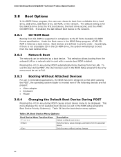
... to be displayed. Boot Device Menu Options Boot Device Menu Function Keys or Description Selects a default boot device Exits the menu, saves changes, and boots from the LAN. If enabled, the last default boot device is the network. 3.8.1 CD-ROM Boot Booting from CD-ROM is not a bootable CD in compliance to boot from the onboard LAN or a network add-in priority order. This selection allows booting from a diskette drive, hard drive, USB drive, USB flash drive, CD-ROM, or the network. Intel Desktop Board DQ35JO Technical Product Specification 3.8 Boot Options In the BIOS Setup...
... to be displayed. Boot Device Menu Options Boot Device Menu Function Keys or Description Selects a default boot device Exits the menu, saves changes, and boots from the LAN. If enabled, the last default boot device is the network. 3.8.1 CD-ROM Boot Booting from CD-ROM is not a bootable CD in compliance to boot from the onboard LAN or a network add-in priority order. This selection allows booting from a diskette drive, hard drive, USB drive, USB flash drive, CD-ROM, or the network. Intel Desktop Board DQ35JO Technical Product Specification 3.8 Boot Options In the BIOS Setup...

Product Specification
Page 68
... and removable media. Intel Desktop Board DQ35JO Technical Product Specification 4.4 Port 80h POST Codes During the POST, the BIOS generates diagnostic progress codes (POST codes) to I /O Busses: PCI, USB, ATA, etc. 5F is an unrecoverable error. Reserved for debug. 10 - 1F Host Processors: 1F is an unrecoverable CPU error. 20 - 2F Memory/Chipset: 2F is an unrecoverable error. D0 - DF Boot device selection. Port 80h POST Code Ranges Range Category/Subsystem 00 - 0F Debug codes: Can be installed in PCI bus connector...
... and removable media. Intel Desktop Board DQ35JO Technical Product Specification 4.4 Port 80h POST Codes During the POST, the BIOS generates diagnostic progress codes (POST codes) to I /O Busses: PCI, USB, ATA, etc. 5F is an unrecoverable error. Reserved for debug. 10 - 1F Host Processors: 1F is an unrecoverable CPU error. 20 - 2F Memory/Chipset: 2F is an unrecoverable error. D0 - DF Boot device selection. Port 80h POST Code Ranges Range Category/Subsystem 00 - 0F Debug codes: Can be installed in PCI bus connector...

Product Specification
Page 69
... Hot Plug PCI controller initialization 53 - 57 Reserved for PCI Bus USB 58 Resetting USB bus 59 Reserved for USB ATA/ATAPI/SATA 5A Resetting PATA/SATA bus and all devices 5B Reserved for ATA SMBus 5C Resetting SMBus 5D Reserved for SMBus Local Console 70 Resetting the VGA controller 71 Disabling the VGA controller 72 Enabling the VGA controller Remote Console 78 Resetting the console controller 79 Disabling the console controller 7A Enabling the console controller continued 69 Error Messages and Beep Codes...
... Hot Plug PCI controller initialization 53 - 57 Reserved for PCI Bus USB 58 Resetting USB bus 59 Reserved for USB ATA/ATAPI/SATA 5A Resetting PATA/SATA bus and all devices 5B Reserved for ATA SMBus 5C Resetting SMBus 5D Reserved for SMBus Local Console 70 Resetting the VGA controller 71 Disabling the VGA controller 72 Enabling the VGA controller Remote Console 78 Resetting the console controller 79 Disabling the console controller 7A Enabling the console controller continued 69 Error Messages and Beep Codes...
Product Specification
Page 71
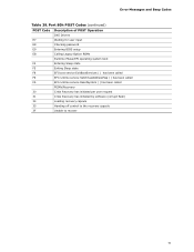
Error Messages and Beep Codes Table 39. Port 80h POST Codes (continued) POST Code Description of POST Operation DXE Drivers E7 Waiting for user input E8 Checking password E9 Entering BIOS setup EB Calling Legacy Option ROMs Runtime Phase/EFI operating system boot F4 Entering Sleep state F5 Exiting Sleep state F8 EFI boot service ExitBootServices ( ) has been called F9 EFI runtime service SetVirtualAddressMap ( ) has been called FA EFI runtime service ResetSystem ( ) has been called PEIMs/Recovery 30...
Error Messages and Beep Codes Table 39. Port 80h POST Codes (continued) POST Code Description of POST Operation DXE Drivers E7 Waiting for user input E8 Checking password E9 Entering BIOS setup EB Calling Legacy Option ROMs Runtime Phase/EFI operating system boot F4 Entering Sleep state F5 Exiting Sleep state F8 EFI boot service ExitBootServices ( ) has been called F9 EFI runtime service SetVirtualAddressMap ( ) has been called FA EFI runtime service ResetSystem ( ) has been called PEIMs/Recovery 30...


