
Product Specification
Page 5
... Options 11 1.1.3 Board Layout 12 1.1.4 Block Diagram 14 1.2 Online Support 15 1.3 Processor 15 1.4 System Memory 16 1.4.1 Memory Configurations 18 1.5 Intel® G965 Express Chipset 23 1.5.1 Intel G965 Graphics Subsystem 23 1.5.2 USB 26 1.5.3 Serial ATA Interfaces 27 1.5.4 Real-Time Clock...28 1.6.1 Audio Subsystem Software 28 1.6.2 Audio Connectors and Headers 29 1.7 LAN Subsystem 30 1.7.1 Intel® 82566DC Gigabit Ethernet Controller 30 1.7.2 LAN Subsystem Software 31 1.7.3 RJ-45 LAN Connector with Integrated LEDs 31 1.8 Hardware Management Subsystem 32 1.8.1 Hardware ...
... Options 11 1.1.3 Board Layout 12 1.1.4 Block Diagram 14 1.2 Online Support 15 1.3 Processor 15 1.4 System Memory 16 1.4.1 Memory Configurations 18 1.5 Intel® G965 Express Chipset 23 1.5.1 Intel G965 Graphics Subsystem 23 1.5.2 USB 26 1.5.3 Serial ATA Interfaces 27 1.5.4 Real-Time Clock...28 1.6.1 Audio Subsystem Software 28 1.6.2 Audio Connectors and Headers 29 1.7 LAN Subsystem 30 1.7.1 Intel® 82566DC Gigabit Ethernet Controller 30 1.7.2 LAN Subsystem Software 31 1.7.3 RJ-45 LAN Connector with Integrated LEDs 31 1.8 Hardware Management Subsystem 32 1.8.1 Hardware ...

Product Specification
Page 8
... and Headers Shown in Figure 16 51 19. Processor Fan Header 51 21. Main Power Connector 54 28. States for a One-Color Power LED 56 30. Fan Header Current Capability 61 35. Beep Codes 75 43. EMC Regulations 87 50. Intel Desktop Board DG965PZ Technical Product Specification 11. I/O ...Program Function Keys 68 39. Port 80h POST Codes 77 46. Interrupts 46 17. Acceptable Drives/Media Types for Components 65 36. Wireless LAN Activity LED Header 52 26. DC Loading Characteristics 61 34. Front Panel Audio Header 52 25. BIOS Setup Configuration Jumper Settings 58 33. ...
... and Headers Shown in Figure 16 51 19. Processor Fan Header 51 21. Main Power Connector 54 28. States for a One-Color Power LED 56 30. Fan Header Current Capability 61 35. Beep Codes 75 43. EMC Regulations 87 50. Intel Desktop Board DG965PZ Technical Product Specification 11. I/O ...Program Function Keys 68 39. Port 80h POST Codes 77 46. Interrupts 46 17. Acceptable Drives/Media Types for Components 65 36. Wireless LAN Activity LED Header 52 26. DC Loading Characteristics 61 34. Front Panel Audio Header 52 25. BIOS Setup Configuration Jumper Settings 58 33. ...

Product Specification
Page 9
1 Product Description What This Chapter Contains 1.1 Overview 10 1.2 Online Support 15 1.3 Processor 15 1.4 System Memory 16 1.5 Intel® G965 Express Chipset 23 1.6 Audio Subsystem 28 1.7 LAN Subsystem 30 1.8 Hardware Management Subsystem 32 1.9 Power Management 34 9
1 Product Description What This Chapter Contains 1.1 Overview 10 1.2 Online Support 15 1.3 Processor 15 1.4 System Memory 16 1.5 Intel® G965 Express Chipset 23 1.6 Audio Subsystem 28 1.7 LAN Subsystem 30 1.8 Hardware Management Subsystem 32 1.9 Power Management 34 9
Product Specification
Page 10
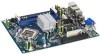
...LAN Support BIOS Instantly Available PC Technology picoBTX Form Factor (8.00 inches by 10.50 inches [203.20 millimeters by 266.70 millimeters]) Support for the following: • Intel® Core™2 Duo processor in an LGA775 socket with a 1066 or 800 MHz system bus • Intel® Pentium® D processor in an LGA775...Four Serial ATA interfaces Gigabit (10/100/1000 Mbits/sec) LAN subsystem using DDR2 800 DIMMs Intel® G965 Express Chipset, consisting of the Desktop Board DG965PZ. Intel Desktop Board DG965PZ Technical Product Specification 1.1 Overview 1.1.1 Feature ...
...LAN Support BIOS Instantly Available PC Technology picoBTX Form Factor (8.00 inches by 10.50 inches [203.20 millimeters by 266.70 millimeters]) Support for the following: • Intel® Core™2 Duo processor in an LGA775 socket with a 1066 or 800 MHz system bus • Intel® Pentium® D processor in an LGA775...Four Serial ATA interfaces Gigabit (10/100/1000 Mbits/sec) LAN subsystem using DDR2 800 DIMMs Intel® G965 Express Chipset, consisting of the Desktop Board DG965PZ. Intel Desktop Board DG965PZ Technical Product Specification 1.1 Overview 1.1.1 Feature ...
Product Specification
Page 13
.../HH I/O Controller Hub (ICH8) J BIOS Setup configuration jumper block K Chassis intrusion header L Front panel header M Auxiliary front panel power LED header N Processor fan header O LGA775 processor socket P Intel 82G965 GMCH Q DIMM Channel A sockets R Processor core power connector S Speaker T DIMM Channel B sockets U PCI Express Mini Card connector V Serial ATA connectors [4] W Rear chassis fan header X High Definition...
.../HH I/O Controller Hub (ICH8) J BIOS Setup configuration jumper block K Chassis intrusion header L Front panel header M Auxiliary front panel power LED header N Processor fan header O LGA775 processor socket P Intel 82G965 GMCH Q DIMM Channel A sockets R Processor core power connector S Speaker T DIMM Channel B sockets U PCI Express Mini Card connector V Serial ATA connectors [4] W Rear chassis fan header X High Definition...

Product Specification
Page 14
PCI Express Mini Card Connector Gigabit Ethernet Controller LAN Connector PCI Express x1 Interface LGA775 Processor Socket System Bus (1066/800/533 MHz) PCI Express x16 Connector PCI Express x16 Interface Display Interface VGA Port Intel G965 Express Chipset Intel 82G965 Graphics and Memory Controller Hub (GMCH) DVI Port Channel A DIMMs (2) Channel B DIMMs (2) Dual-Channel Memory Bus...
PCI Express Mini Card Connector Gigabit Ethernet Controller LAN Connector PCI Express x1 Interface LGA775 Processor Socket System Bus (1066/800/533 MHz) PCI Express x16 Connector PCI Express x16 Interface Display Interface VGA Port Intel G965 Express Chipset Intel 82G965 Graphics and Memory Controller Hub (GMCH) DVI Port Channel A DIMMs (2) Channel B DIMMs (2) Dual-Channel Memory Bus...
Product Specification
Page 15
... to support the following processors: • Intel Core 2 Duo processor in an LGA775 socket with a 1066 or 800 MHz system bus • Intel Pentium D processor in an LGA775 processor socket with an 800 or 533 MHz system bus • Intel Pentium 4 processor in an LGA775 processor socket with an 800 or 533 MHz system bus • Intel Celeron D processor in an LGA775 processor socket with a 533 MHz...
... to support the following processors: • Intel Core 2 Duo processor in an LGA775 socket with a 1066 or 800 MHz system bus • Intel Pentium D processor in an LGA775 processor socket with an 800 or 533 MHz system bus • Intel Pentium 4 processor in an LGA775 processor socket with an 800 or 533 MHz system bus • Intel Celeron D processor in an LGA775 processor socket with a 533 MHz...

Product Specification
Page 17
Product Description NOTE Regardless of DIMMs and processors. Table 5. Memory Operating Frequencies DIMM Type Processor system bus frequency DDR2 533 533 MHz DDR2 533 800 MHz DDR2 533 1066 MHz DDR2 667 533 MHz DDR2 667 800 MHz DDR2 667 1066 MHz DDR2 800 533 MHz DDR2 800 800 MHz DDR2 800 1066 MHz Resulting memory frequency 533 MHz 533 MHz 533 MHz 533 MHz...
Product Description NOTE Regardless of DIMMs and processors. Table 5. Memory Operating Frequencies DIMM Type Processor system bus frequency DDR2 533 533 MHz DDR2 533 800 MHz DDR2 533 1066 MHz DDR2 667 533 MHz DDR2 667 800 MHz DDR2 667 1066 MHz DDR2 800 533 MHz DDR2 800 800 MHz DDR2 800 1066 MHz Resulting memory frequency 533 MHz 533 MHz 533 MHz 533 MHz...

Product Specification
Page 32
... the hardware monitoring and fan control include: • Intel Quiet System Technology, delivering acoustically-optimized thermal management • Fan speed control controllers and sensors integrated into the ICH8 • Four thermal sensors (processor, 82G965 GMCH, 82801HR/HH ICH8, and a remote thermal... VSB, +1.25 V, and +VCCP) to detect levels above or below acceptable values • Thermally monitored closed position. Intel Desktop Board DG965PZ Technical Product Specification 1.8 Hardware Management Subsystem The hardware management features enable the board to be implemented using...
... the hardware monitoring and fan control include: • Intel Quiet System Technology, delivering acoustically-optimized thermal management • Fan speed control controllers and sensors integrated into the ICH8 • Four thermal sensors (processor, 82G965 GMCH, 82801HR/HH ICH8, and a remote thermal... VSB, +1.25 V, and +VCCP) to detect levels above or below acceptable values • Thermally monitored closed position. Intel Desktop Board DG965PZ Technical Product Specification 1.8 Hardware Management Subsystem The hardware management features enable the board to be implemented using...

Product Specification
Page 33
Thermal Sensors and Fan Headers 33 Item A B C D E F G Description Thermal diode, located on processor die Thermal diode, located on the GMCH die Thermal diode, located on the ICH8 die Remote thermal sensor Processor fan Front chassis fan Rear chassis fan Figure 12. Product Description 1.8.4 Thermal Monitoring Figure 12 shows the locations of the thermal sensors and fan headers.
Thermal Sensors and Fan Headers 33 Item A B C D E F G Description Thermal diode, located on processor die Thermal diode, located on the GMCH die Thermal diode, located on the ICH8 die Remote thermal sensor Processor fan Front chassis fan Rear chassis fan Figure 12. Product Description 1.8.4 Thermal Monitoring Figure 12 shows the locations of the thermal sensors and fan headers.
Product Specification
Page 35
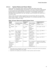
... board along with the associated system power targets. Table 10. sleeping N/A state C1 - Context saved to RAM. Power States and Targeted System Power Global States Processor Sleeping States States Device States Targeted System Power (Note 1) G0 - S4 - Product Description 1.9.1.1 System States and Power States Under ACPI, the operating system directs all...
... board along with the associated system power targets. Table 10. sleeping N/A state C1 - Context saved to RAM. Power States and Targeted System Power Global States Processor Sleeping States States Device States Targeted System Power (Note 1) G0 - S4 - Product Description 1.9.1.1 System States and Power States Under ACPI, the operating system directs all...
Product Specification
Page 37
...computer's response can turn off ). For information about The locations of the fan headers and thermal sensors The signal names of the processor fan header The signal names of the chassis fan headers Refer to a fan tachometer input of Resume on Ring and Wake from ... removes all non-standby voltages. Product Description • Wake from USB • WAKE# signal wake-up support • Intel Quick Resume Technology Drivers (QRTD) (optional) LAN wake capabilities and Instantly Available PC technology require power from an ACPI state requires an operating system that can adjust the fan...
...computer's response can turn off ). For information about The locations of the fan headers and thermal sensors The signal names of the processor fan header The signal names of the chassis fan headers Refer to a fan tachometer input of Resume on Ring and Wake from ... removes all non-standby voltages. Product Description • Wake from USB • WAKE# signal wake-up support • Intel Quick Resume Technology Drivers (QRTD) (optional) LAN wake capabilities and Instantly Available PC technology require power from an ACPI state requires an operating system that can adjust the fan...

Product Specification
Page 51
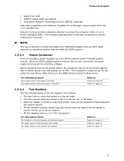
Processor Fan Header Pin Signal Name 1 Ground 2 +12 V 3 FAN_TACH 4 FAN_CONTROL Table 21. Chassis Intrusion Header Pin Signal Name 1 Intruder 2 Ground 51 Technical Reference ...header F Main power connector G Chassis intrusion header H Front panel header I Auxiliary front panel power LED header J Processor fan connector K Processor core power connector L PCI Express Mini Card connector M Serial ATA connectors [4] N Wireless LAN activity LED header O Rear chassis fan header P High Definition Audio Link header Q Front panel audio header Table 19...
Processor Fan Header Pin Signal Name 1 Ground 2 +12 V 3 FAN_TACH 4 FAN_CONTROL Table 21. Chassis Intrusion Header Pin Signal Name 1 Intruder 2 Ground 51 Technical Reference ...header F Main power connector G Chassis intrusion header H Front panel header I Auxiliary front panel power LED header J Processor fan connector K Processor core power connector L PCI Express Mini Card connector M Serial ATA connectors [4] N Wireless LAN activity LED header O Rear chassis fan header P High Definition Audio Link header Q Front panel audio header Table 19...

Product Specification
Page 54
... provides power directly to do so will be used on Intel Desktop boards. a 2 x 2 connector. Processor Core Power Connector Pin Signal Name Pin Signal Name 1 Ground 3 +12 V 2 Ground 4 +12 V Table 27. Table 26. Failure to the processor voltage regulator and must always be unconnected. 54 The board... supports the use of the main power connector, leaving pins 11, 12, 23, and 24 unconnected. • Processor core power - When using a power supply with a 2 x 10 main power cable, attach that cable on /off) 5 Ground 17 Ground 6 ...
... provides power directly to do so will be used on Intel Desktop boards. a 2 x 2 connector. Processor Core Power Connector Pin Signal Name Pin Signal Name 1 Ground 3 +12 V 2 Ground 4 +12 V Table 27. Table 26. Failure to the processor voltage regulator and must always be unconnected. 54 The board... supports the use of the main power connector, leaving pins 11, 12, 23, and 24 unconnected. • Processor core power - When using a power supply with a 2 x 10 main power cable, attach that cable on /off) 5 Ground 17 Ground 6 ...

Product Specification
Page 58
...current configuration information and passwords for the three modes: normal, configure, and recovery. The maintenance menu is powered-up, the BIOS compares the processor version and the microcode version in the BIOS and reports if the two match. Always turn off the power and unplug the power cord from... 32. See Section 3.7 for more information on . Location of the jumper block. When the jumper is set to recover the BIOS configuration. Intel Desktop Board DG965PZ Technical Product Specification 2.8 Jumper Block CAUTION Do not move the jumper with the power on BIOS recovery. 58
...current configuration information and passwords for the three modes: normal, configure, and recovery. The maintenance menu is powered-up, the BIOS compares the processor version and the microcode version in the BIOS and reports if the two match. Always turn off the power and unplug the power cord from... 32. See Section 3.7 for more information on . Location of the jumper block. When the jumper is set to recover the BIOS configuration. Intel Desktop Board DG965PZ Technical Product Specification 2.8 Jumper Block CAUTION Do not move the jumper with the power on BIOS recovery. 58

Product Specification
Page 61
... no USB current draw. The selection of all active components within the board that will halt fan operation. These calculations are not based on specific processor values or memory configurations but are based on a DC analysis of a power supply at : +12 V -12 V 5.53 A 0.00 A 15.52 A 0.00 A +5 VSB 1.06 A...dependent on the system's usage model and not necessarily tied to a chassis fan header. Use the datasheets for add-in cards. Connecting the processor fan to an environment with a 500 mA current draw per USB port. This data is similar to a chassis fan header may result in...
... no USB current draw. The selection of all active components within the board that will halt fan operation. These calculations are not based on specific processor values or memory configurations but are based on a DC analysis of a power supply at : +12 V -12 V 5.53 A 0.00 A 15.52 A 0.00 A +5 VSB 1.06 A...dependent on the system's usage model and not necessarily tied to a chassis fan header. Use the datasheets for add-in cards. Connecting the processor fan to an environment with a 500 mA current draw per USB port. This data is similar to a chassis fan header may result in...

Product Specification
Page 63
... that proper airflow is maintained in the processor voltage regulator circuit. Failure to ensure appropriate airflow may result in damage to the following the instructions presented in this document will result in a system with Intel desktop boards please refer to the voltage ... the board's maximum operating temperature. CAUTION Ensure that merely following website: http://developer.intel.com/design/motherbd/cooling.htm All responsibility for the processor. For a list of both the processor and/or voltage regulator or, in some instances, damage to exceed their maximum case...
... that proper airflow is maintained in the processor voltage regulator circuit. Failure to ensure appropriate airflow may result in damage to the following the instructions presented in this document will result in a system with Intel desktop boards please refer to the voltage ... the board's maximum operating temperature. CAUTION Ensure that merely following website: http://developer.intel.com/design/motherbd/cooling.htm All responsibility for the processor. For a list of both the processor and/or voltage regulator or, in some instances, damage to exceed their maximum case...

Product Specification
Page 64
Intel Desktop Board DG965PZ Technical Product Specification Figure 23 shows the locations of the localized high temperature zones. Localized High Temperature Zones 64 Item A B C D E Description Intel 82801HR/HH ICH8 1.5 V core and front side bus voltage regulator areas Processor Processor voltage regulator area Intel 82G965 GMCH Figure 23.
Intel Desktop Board DG965PZ Technical Product Specification Figure 23 shows the locations of the localized high temperature zones. Localized High Temperature Zones 64 Item A B C D E Description Intel 82801HR/HH ICH8 1.5 V core and front side bus voltage regulator areas Processor Processor voltage regulator area Intel 82G965 GMCH Figure 23.

Product Specification
Page 65
... Table 35 provides maximum case temperatures for Components Component Maximum Case Temperature Processor For processor case temperature, see processor datasheets and processor specification updates Intel 82G965 GMCH Intel 82801HR/HH ICH8R/ICH8DH 97 oC (under bias) 105 oC (under bias) For information about Processor datasheets and specification updates Refer to estimate repair rates and spare parts requirements...
... Table 35 provides maximum case temperatures for Components Component Maximum Case Temperature Processor For processor case temperature, see processor datasheets and processor specification updates Intel 82G965 GMCH Intel 82801HR/HH ICH8R/ICH8DH 97 oC (under bias) 105 oC (under bias) For information about Processor datasheets and specification updates Refer to estimate repair rates and spare parts requirements...
Product Specification
Page 68
Table 37. PCI devices may be available for use by the add-in cards. Table 38. Intel Desktop Board DG965PZ Technical Product Specification Table 37 lists the BIOS Setup program menu features. Autoconfiguration lets a user insert or ... to be onboard or add-in card. 68 BIOS Setup Program Menu Bar Maintenance Main Advanced Security Clears passwords and displays processor information Displays processor and memory configuration Configures advanced features available through the chipset Sets passwords and security features Power Configures power management features and power...
Table 37. PCI devices may be available for use by the add-in cards. Table 38. Intel Desktop Board DG965PZ Technical Product Specification Table 37 lists the BIOS Setup program menu features. Autoconfiguration lets a user insert or ... to be onboard or add-in card. 68 BIOS Setup Program Menu Bar Maintenance Main Advanced Security Clears passwords and displays processor information Displays processor and memory configuration Configures advanced features available through the chipset Sets passwords and security features Power Configures power management features and power...


