
Product Specification
Page 6
... Flash Memory Organization 68 3.3 Resource Configuration 68 3.3.1 PCI Autoconfiguration 68 3.4 System Management BIOS (SMBIOS 69 3.5 Legacy USB Support 69 3.6 BIOS Updates 70 3.6.1 Language Support 70 3.6.2 Custom Splash Screen 70 3.7 BIOS Recovery 71 3.8 Boot Options 71 3.8.1 CD-ROM Boot 71 3.8.2 Network Boot 71 3.8.3 Booting Without Attached Devices 72 3.8.4 Changing the Default Boot Device During POST 72 3.9 Adjusting Boot Speed 73 3.9.1 Peripheral Selection and Configuration 73 3.9.2 BIOS Boot Optimizations 73 3.10 BIOS Security Features 74 4 Error Messages and Beep Codes...
... Flash Memory Organization 68 3.3 Resource Configuration 68 3.3.1 PCI Autoconfiguration 68 3.4 System Management BIOS (SMBIOS 69 3.5 Legacy USB Support 69 3.6 BIOS Updates 70 3.6.1 Language Support 70 3.6.2 Custom Splash Screen 70 3.7 BIOS Recovery 71 3.8 Boot Options 71 3.8.1 CD-ROM Boot 71 3.8.2 Network Boot 71 3.8.3 Booting Without Attached Devices 72 3.8.4 Changing the Default Boot Device During POST 72 3.9 Adjusting Boot Speed 73 3.9.1 Peripheral Selection and Configuration 73 3.9.2 BIOS Boot Optimizations 73 3.10 BIOS Security Features 74 4 Error Messages and Beep Codes...

Product Specification
Page 7
Block Diagram 14 3. Dual Channel (Interleaved) Mode Configuration with Three DIMMs....... 21 9. Single Channel (Asymmetric) Mode Configuration with Three DIMMs ......... 19 6. Thermal Sensors and Fan Headers 33 13. Back Panel Connectors 49 16. Connection Diagram for Front Panel Header 55 18. Feature Summary 10 2. Supported Memory Configurations 16 5. Power States and Targeted System Power 35 vii LAN Connector LED Locations 31 12. Connection Diagram for Front Panel USB Headers 57 19. LAN Connector LED States 31 9. Location of the Jumper Block...
Block Diagram 14 3. Dual Channel (Interleaved) Mode Configuration with Three DIMMs....... 21 9. Single Channel (Asymmetric) Mode Configuration with Three DIMMs ......... 19 6. Thermal Sensors and Fan Headers 33 13. Back Panel Connectors 49 16. Connection Diagram for Front Panel Header 55 18. Feature Summary 10 2. Supported Memory Configurations 16 5. Power States and Targeted System Power 35 vii LAN Connector LED Locations 31 12. Connection Diagram for Front Panel USB Headers 57 19. LAN Connector LED States 31 9. Location of the Jumper Block...

Product Specification
Page 8
... 36. BIOS Setup Configuration Jumper Settings 58 33. BIOS Setup Program Function Keys 68 39. Beep Codes 75 43. Wireless LAN Activity LED Header 52 26. Auxiliary Front Panel Power LED Header 56 32. Desktop Board DG965PZ Environmental Specifications 66 37. Processor Fan Header 51 21. Typical Port 80h POST Sequence 80 47. Product Certification Markings 88 viii Main Power Connector 54 28. Thermal Considerations for a One-Color Power LED 56 30. Chassis Intrusion Header 51 22. Interrupts 46 17. Wake-up Devices and...
... 36. BIOS Setup Configuration Jumper Settings 58 33. BIOS Setup Program Function Keys 68 39. Beep Codes 75 43. Wireless LAN Activity LED Header 52 26. Auxiliary Front Panel Power LED Header 56 32. Desktop Board DG965PZ Environmental Specifications 66 37. Processor Fan Header 51 21. Typical Port 80h POST Sequence 80 47. Product Certification Markings 88 viii Main Power Connector 54 28. Thermal Considerations for a One-Color Power LED 56 30. Chassis Intrusion Header 51 22. Interrupts 46 17. Wake-up Devices and...
Product Specification
Page 10
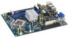
... X3000 onboard graphics subsystem Refer to Table 2 on page 11 for a list of manufacturing options Support for USB 2.0 devices • 10 USB ports • Two IEEE-1394a interfaces: one back panel connector and one front-panel header • Four Serial ATA interfaces Gigabit (10/100/1000 Mbits/sec) LAN subsystem using DDR2 800 DIMMs Intel® G965 Express Chipset, consisting of manufacturing options for the ICH8 component. Feature Summary Form Factor Processor Memory Chipset Video Audio USB...
... X3000 onboard graphics subsystem Refer to Table 2 on page 11 for a list of manufacturing options Support for USB 2.0 devices • 10 USB ports • Two IEEE-1394a interfaces: one back panel connector and one front-panel header • Four Serial ATA interfaces Gigabit (10/100/1000 Mbits/sec) LAN subsystem using DDR2 800 DIMMs Intel® G965 Express Chipset, consisting of manufacturing options for the ICH8 component. Feature Summary Form Factor Processor Memory Chipset Video Audio USB...

Product Specification
Page 14
...LAN Connector PCI Express x1 Interface LGA775 Processor Socket System Bus (1066/800/533 MHz) PCI Express x16 Connector PCI Express x16 Interface Display Interface VGA Port Intel G965 Express Chipset Intel 82G965 Graphics and Memory Controller Hub (GMCH) DVI Port Channel A DIMMs (2) Channel B DIMMs (2) Dual-Channel Memory Bus SMBus IEEE-1394a Connector/Header IEEE-1394a Controller DMI Interconnect USB Intel 82801HR/HH I/O Controller Hub (ICH8R/ICH8DH) Back Panel/Front Panel USB Ports Serial Peripheral Interface (SPI) Flash Device Serial ATA IDE Interface Serial ATA IDE Connectors...
...LAN Connector PCI Express x1 Interface LGA775 Processor Socket System Bus (1066/800/533 MHz) PCI Express x16 Connector PCI Express x16 Interface Display Interface VGA Port Intel G965 Express Chipset Intel 82G965 Graphics and Memory Controller Hub (GMCH) DVI Port Channel A DIMMs (2) Channel B DIMMs (2) Dual-Channel Memory Bus SMBus IEEE-1394a Connector/Header IEEE-1394a Controller DMI Interconnect USB Intel 82801HR/HH I/O Controller Hub (ICH8R/ICH8DH) Back Panel/Front Panel USB Ports Serial Peripheral Interface (SPI) Flash Device Serial ATA IDE Interface Serial ATA IDE Connectors...

Product Specification
Page 16
... may not function under the determined frequency. This enables the BIOS to read the SPD data and program the chipset to accurately configure memory settings for information on page 41 for optimum performance. Table 4 lists the supported DIMM configurations. Table 4. Intel Desktop Board DG965PZ Technical Product Specification 1.4 System Memory The board has four DIMM sockets and supports the following memory features: • 1.8 V (only) DDR2 SDRAM DIMMs with gold-plated contacts...
... may not function under the determined frequency. This enables the BIOS to read the SPD data and program the chipset to accurately configure memory settings for information on page 41 for optimum performance. Table 4 lists the supported DIMM configurations. Table 4. Intel Desktop Board DG965PZ Technical Product Specification 1.4 System Memory The board has four DIMM sockets and supports the following memory features: • 1.8 V (only) DDR2 SDRAM DIMMs with gold-plated contacts...
Product Specification
Page 25
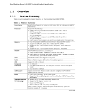
... 1.2, page 15 1.5.1.4 Digital Video Interface (DVI) The DVI port supports only DVI-D displays. DVMT returns system memory back to the graphics buffer as a downloadable document. An example of add-in card installed in the PCI Express x16 connector, the DVI port will behave as set in the BIOS Setup program) for performing graphics functions. Table 6. If a DVI-I display is connected, only the digital signal will always use a minimal fixed portion...
... 1.2, page 15 1.5.1.4 Digital Video Interface (DVI) The DVI port supports only DVI-D displays. DVMT returns system memory back to the graphics buffer as a downloadable document. An example of add-in card installed in the PCI Express x16 connector, the DVI port will behave as set in the BIOS Setup program) for performing graphics functions. Table 6. If a DVI-I display is connected, only the digital signal will always use a minimal fixed portion...

Product Specification
Page 26
... Voltage Differential Signaling (LVDS) • Single device operating in dual channel mode • VGA output • HDTV output • HDMI/UDI support (when used with the primary VGA display or can be accessed by the ADD2/MEC card. An ADD2/MEC card can be paired for all ports. When an ADD2/MEC card is detected, the Intel GMA X3000 graphics controller is enabled and the PCI Express x16 connector is attached to the cable...
... Voltage Differential Signaling (LVDS) • Single device operating in dual channel mode • VGA output • HDTV output • HDMI/UDI support (when used with the primary VGA display or can be accessed by the ADD2/MEC card. An ADD2/MEC card can be paired for all ports. When an ADD2/MEC card is detected, the Intel GMA X3000 graphics controller is enabled and the PCI Express x16 connector is attached to the cable...

Product Specification
Page 27
... battery (CR2032) powers the real-time clock and CMOS memory. The clock is the preferred mode for a maximum of 3 Gbits/sec per channel. Figure 1 on each port for configurations using the Windows* XP and Windows 2000 operating systems. NOTE Many Serial ATA drives use new low-voltage power connectors and require adaptors or power supplies equipped with 3.3 VSB applied. data striping and mirroring • RAID 5 - Replace the battery with an equivalent one device per connector. 1.5.3.1 Serial ATA Support...
... battery (CR2032) powers the real-time clock and CMOS memory. The clock is the preferred mode for a maximum of 3 Gbits/sec per channel. Figure 1 on each port for configurations using the Windows* XP and Windows 2000 operating systems. NOTE Many Serial ATA drives use new low-voltage power connectors and require adaptors or power supplies equipped with 3.3 VSB applied. data striping and mirroring • RAID 5 - Replace the battery with an equivalent one device per connector. 1.5.3.1 Serial ATA Support...

Product Specification
Page 34
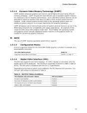
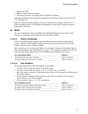
...; Support for a front panel power and sleep mode switch Table 9 lists the system states based on how long the power switch is pressed, depending on how ACPI is configured with the board requires an operating system that provides full ACPI support. The use of individual devices, add-in boards (some add-in boards may require an ACPI-aware driver), video displays, and hard disk drives • Methods for achieving less than four seconds ...the system enters this...
...; Support for a front panel power and sleep mode switch Table 9 lists the system states based on how long the power switch is pressed, depending on how ACPI is configured with the board requires an operating system that provides full ACPI support. The use of individual devices, add-in boards (some add-in boards may require an ACPI-aware driver), video displays, and hard disk drives • Methods for achieving less than four seconds ...the system enters this...
Product Specification
Page 36
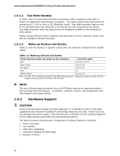
... connected to the S5 state when the computer is disabled by operating at 1.5 W (or less) in the S5 state. Intel Desktop Board DG965PZ Technical Product Specification 1.9.1.2 Two-Watt Standby In 2001, the U.S. NOTE The use of standby current required depends on Ring 36 In addition, software, drivers, and peripherals must fully support ACPI wake events. 1.9.2 Hardware Support CAUTION Ensure that requirement by default in power...
... connected to the S5 state when the computer is disabled by operating at 1.5 W (or less) in the S5 state. Intel Desktop Board DG965PZ Technical Product Specification 1.9.1.2 Two-Watt Standby In 2001, the U.S. NOTE The use of standby current required depends on Ring 36 In addition, software, drivers, and peripherals must fully support ACPI wake events. 1.9.2 Hardware Support CAUTION Ensure that requirement by default in power...
Product Specification
Page 37
... technology require power from an ACPI state requires an operating system that can be set using the Last Power State feature in the BIOS Setup program's Boot menu. When resuming from an AC power failure, the computer returns to a fan tachometer input of telephony device (external or internal). When an ACPI-enabled system receives the correct command, the power supply removes all non-standby voltages. For information about The location of the main power connector...
... technology require power from an ACPI state requires an operating system that can be set using the Last Power State feature in the BIOS Setup program's Boot menu. When resuming from an AC power failure, the computer returns to a fan tachometer input of telephony device (external or internal). When an ACPI-enabled system receives the correct command, the power supply removes all non-standby voltages. For information about The location of the main power connector...
Product Specification
Page 42
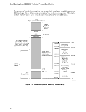
... BIOS settings. All installed system memory can be used will vary based on add-in Card BIOS and Buffer area (128 KB; 16 KB x 8) Standard PCI/ ISA Video Memory (SMM Memory) 128 KB DOS area (640 KB) 1 MB 960 KB 896 KB 768 KB 640 KB 0 KB OM18311 Figure 14. Detailed System Memory Address Map 42 Intel Desktop Board DG965PZ Technical Product Specification The amount of installed memory...
... BIOS settings. All installed system memory can be used will vary based on add-in Card BIOS and Buffer area (128 KB; 16 KB x 8) Standard PCI/ ISA Video Memory (SMM Memory) 128 KB DOS area (640 KB) 1 MB 960 KB 896 KB 768 KB 640 KB 0 KB OM18311 Figure 14. Detailed System Memory Address Map 42 Intel Desktop Board DG965PZ Technical Product Specification The amount of installed memory...

Product Specification
Page 67
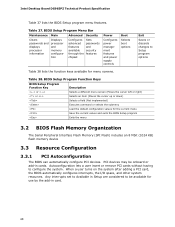
... 67 3.2 BIOS Flash Memory Organization 68 3.3 Resource Configuration 68 3.4 System Management BIOS (SMBIOS 69 3.5 Legacy USB Support 69 3.6 BIOS Updates 70 3.7 BIOS Recovery 71 3.8 Boot Options 71 3.9 Adjusting Boot Speed 73 3.10 BIOS Security Features 74 3.1 Introduction The board uses an Intel BIOS that is in the Serial Peripheral Interface Flash Memory (SPI Flash) and can be updated using a disk-based program. Maintenance Main Advanced Security Power Boot Exit NOTE The maintenance menu is displayed only when the board is stored in configure mode.
... 67 3.2 BIOS Flash Memory Organization 68 3.3 Resource Configuration 68 3.4 System Management BIOS (SMBIOS 69 3.5 Legacy USB Support 69 3.6 BIOS Updates 70 3.7 BIOS Recovery 71 3.8 Boot Options 71 3.9 Adjusting Boot Speed 73 3.10 BIOS Security Features 74 3.1 Introduction The board uses an Intel BIOS that is in the Serial Peripheral Interface Flash Memory (SPI Flash) and can be updated using a disk-based program. Maintenance Main Advanced Security Power Boot Exit NOTE The maintenance menu is displayed only when the board is stored in configure mode.
Product Specification
Page 68
... Setup Program Menu Bar Maintenance Main Advanced Security Clears passwords and displays processor information Displays processor and memory configuration Configures advanced features available through the chipset Sets passwords and security features Power Configures power management features and power supply controls Boot Selects boot options Exit Saves or discards changes to configure the system. Any interrupts set to Available in Setup are considered to be onboard or add-in card. 68 When a user turns on the system after adding a PCI card, the BIOS automatically configures...
... Setup Program Menu Bar Maintenance Main Advanced Security Clears passwords and displays processor information Displays processor and memory configuration Configures advanced features available through the chipset Sets passwords and security features Power Configures power management features and power supply controls Boot Selects boot options Exit Saves or discards changes to configure the system. Any interrupts set to Available in Setup are considered to be onboard or add-in card. 68 When a user turns on the system after adding a PCI card, the BIOS automatically configures...

Product Specification
Page 71
... the Boot menu in card with a 1.44 MB diskette) No USB hard disk drive No For information about BIOS recovery Refer to http://support.intel.com/support/motherboards/desktop 3.8 Boot Options In the BIOS Setup program, the user can choose to the El Torito bootable CD-ROM format specification. To use this key during POST automatically forces booting from the onboard LAN or a network add-in the BIOS Setup program, ATAPI CDROM is listed as a boot device. Table 39 lists the drives and media types that...
... the Boot menu in card with a 1.44 MB diskette) No USB hard disk drive No For information about BIOS recovery Refer to http://support.intel.com/support/motherboards/desktop 3.8 Boot Options In the BIOS Setup program, the user can choose to the El Torito bootable CD-ROM format specification. To use this key during POST automatically forces booting from the onboard LAN or a network add-in the BIOS Setup program, ATAPI CDROM is listed as a boot device. Table 39 lists the drives and media types that...
Product Specification
Page 74
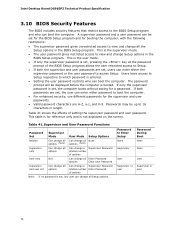
... Can change all options Can change a Supervisor Password limited number of options User only N/A Can change all Enter Password options Clear User Password Supervisor and user set Can change all options Can change a Supervisor Password limited number Enter Password of setting the supervisor password and user password. Intel Desktop Board DG965PZ Technical Product Specification 3.10 BIOS Security Features The BIOS includes security features that restrict access to view and change all the Setup options in the BIOS Setup program. A supervisor password and a user password can boot the...
... Can change all options Can change a Supervisor Password limited number of options User only N/A Can change all Enter Password options Clear User Password Supervisor and user set Can change all options Can change a Supervisor Password limited number Enter Password of setting the supervisor password and user password. Intel Desktop Board DG965PZ Technical Product Specification 3.10 BIOS Security Features The BIOS includes security features that restrict access to view and change all the Setup options in the BIOS Setup program. A supervisor password and a user password can boot the...

Product Specification
Page 76
... future use . FF F0 - Host Processors: 1F is an unrecoverable CPU error. 20 - 2F Memory/Chipset: 2F is no memory detected or no useful memory detected. 30 - 3F Recovery: 3F indicated recovery failure. 40 - 4F Reserved for future use . 50 - 5F I /O port 80h. EE: Miscellaneous codes. Displaying the POST-codes requires a PCI bus add-in card, often called a POST card. DF Boot device selection. E0 - Reserved for future use (new output console codes). 90 - 9F Input devices: Keyboard/Mouse...
... future use . FF F0 - Host Processors: 1F is an unrecoverable CPU error. 20 - 2F Memory/Chipset: 2F is no memory detected or no useful memory detected. 30 - 3F Recovery: 3F indicated recovery failure. 40 - 4F Reserved for future use . 50 - 5F I /O port 80h. EE: Miscellaneous codes. Displaying the POST-codes requires a PCI bus add-in card, often called a POST card. DF Boot device selection. E0 - Reserved for future use (new output console codes). 90 - 9F Input devices: Keyboard/Mouse...

Product Specification
Page 77
... Configuring memory 26 Optimizing memory settings 27 Initializing memory, such as ECC init 28 Testing memory PCI Bus 50 Enumerating PCI busses 51 Allocating resources to PCI bus 52 53 - 57 Hot Plug PCI controller initialization Reserved for PCI Bus USB 58 Resetting USB bus 59 Reserved for USB ATA/ATAPI/SATA 5A Resetting PATA/SATA bus and all devices 5B Reserved for ATA SMBus 5C Resetting SMBUS 5D Reserved for SMBUS Local Console 70 Resetting the VGA controller 71 Disabling...
... Configuring memory 26 Optimizing memory settings 27 Initializing memory, such as ECC init 28 Testing memory PCI Bus 50 Enumerating PCI busses 51 Allocating resources to PCI bus 52 53 - 57 Hot Plug PCI controller initialization Reserved for PCI Bus USB 58 Resetting USB bus 59 Reserved for USB ATA/ATAPI/SATA 5A Resetting PATA/SATA bus and all devices 5B Reserved for ATA SMBus 5C Resetting SMBUS 5D Reserved for SMBUS Local Console 70 Resetting the VGA controller 71 Disabling...
Product Specification
Page 79
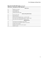
Error Messages and Beep Codes Table 45. Port 80h POST Codes (continued) POST Code Description of POST Operation DXE Drivers E7 Waiting for user input E8 Checking password E9 Entering BIOS setup EB Calling Legacy Option ROMs Runtime Phase/EFI OS Boot F4 Entering Sleep state F5 Exiting Sleep state F8 EFI boot service ExitBootServices ( ) has been called F9 EFI runtime service SetVirtualAddressMap ( ) has been called FA EFI runtime service ResetSystem ( ) has been called PEIMs/Recovery 30 Crisis...
Error Messages and Beep Codes Table 45. Port 80h POST Codes (continued) POST Code Description of POST Operation DXE Drivers E7 Waiting for user input E8 Checking password E9 Entering BIOS setup EB Calling Legacy Option ROMs Runtime Phase/EFI OS Boot F4 Entering Sleep state F5 Exiting Sleep state F8 EFI boot service ExitBootServices ( ) has been called F9 EFI runtime service SetVirtualAddressMap ( ) has been called FA EFI runtime service ResetSystem ( ) has been called PEIMs/Recovery 30 Crisis...


