Product Guide
Page 3
... Product Guide are arranged as Information Technology Equipment (I.T.E.) for use in personal computers (PC) for installation in this product for other PC or embedded non-PC applications or other hardware components 3 Updating the BIOS: instructions on how to update the BIOS A Error Messages and Indicators: information about BIOS error messages and beep codes B Regulatory Compliance: information about board layout, component installation, BIOS update, and regulatory requirements for Intel® Desktop Board DG31PR...
... Product Guide are arranged as Information Technology Equipment (I.T.E.) for use in personal computers (PC) for installation in this product for other PC or embedded non-PC applications or other hardware components 3 Updating the BIOS: instructions on how to update the BIOS A Error Messages and Indicators: information about BIOS error messages and beep codes B Regulatory Compliance: information about board layout, component installation, BIOS update, and regulatory requirements for Intel® Desktop Board DG31PR...
Product Guide
Page 5
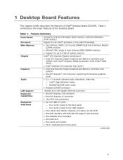
... Processor ...13 Main Memory...13 Intel® G31 Express Chipset 14 Intel® G33 Graphics Subsystem 15 Intel® GMA 3100 Graphics Controller (Intel® GMA 3100 15 Audio Subsystem 16 Legacy Input/Output (I/O) Controller 17 LAN Subsystem 17 RJ-45 LAN Connector LEDs 17 Hi-Speed USB 2.0 Support 18 Enhanced IDE Interface 18 Serial ATA...18 Expandability...19 BIOS ...19 Serial ATA and IDE Auto Configuration 19 PCI* and PCI Express* Auto Configuration 19 Security Passwords 20 Hardware Management Features 20 Hardware Monitoring and Fan Speed Control 21 Chassis...
... Processor ...13 Main Memory...13 Intel® G31 Express Chipset 14 Intel® G33 Graphics Subsystem 15 Intel® GMA 3100 Graphics Controller (Intel® GMA 3100 15 Audio Subsystem 16 Legacy Input/Output (I/O) Controller 17 LAN Subsystem 17 RJ-45 LAN Connector LEDs 17 Hi-Speed USB 2.0 Support 18 Enhanced IDE Interface 18 Serial ATA...18 Expandability...19 BIOS ...19 Serial ATA and IDE Auto Configuration 19 PCI* and PCI Express* Auto Configuration 19 Security Passwords 20 Hardware Management Features 20 Hardware Monitoring and Fan Speed Control 21 Chassis...
Product Guide
Page 6
... the Serial Port Header 47 Connecting to the Alternate Front Panel Power LED Header 47 Connecting to the Front Panel Header 48 Connecting to the USB 2.0 Headers 48 Connecting to the Audio System 49 Connecting Chassis Fan and Power Supply Cables 50 Connecting Chassis Fan Cables 50 Connecting Supply Power Cables 51 Setting the BIOS Configuration Jumper 52 Clearing Passwords 53 Replacing the Battery 54 3 Updating the BIOS Updating the BIOS with the Intel® Express BIOS Update Utility 59 Updating the BIOS with the ISO Image BIOS Update File or the Iflash Memory Update Utility ...60...
... the Serial Port Header 47 Connecting to the Alternate Front Panel Power LED Header 47 Connecting to the Front Panel Header 48 Connecting to the USB 2.0 Headers 48 Connecting to the Audio System 49 Connecting Chassis Fan and Power Supply Cables 50 Connecting Chassis Fan Cables 50 Connecting Supply Power Cables 51 Setting the BIOS Configuration Jumper 52 Clearing Passwords 53 Replacing the Battery 54 3 Updating the BIOS Updating the BIOS with the Intel® Express BIOS Update Utility 59 Updating the BIOS with the ISO Image BIOS Update File or the Iflash Memory Update Utility ...60...
Product Guide
Page 7
...20. Internal Headers and Connectors 45 22. Serial Port Header Signal Names 47 8. USB 2.0 Header Signal Names 48 11. Front Panel Header 48 10. Location of the Chassis Fan Headers 50 24. Chassis Intrusion Header 46 7. S/PDIF Connector 46 6. Install the Processor 33 11. Use DDR2 DIMMs 37 15. Location of the BIOS Configuration Jumper Block 52 26. Front Panel Intel High Definition Audio Header Signal Names 46 5. Connecting a Serial ATA Cable 44 21. Remove the Protective Socket Cover 32 9. Desktop Board DG31PR Components 11 2. LAN Connector LEDs 17...
...20. Internal Headers and Connectors 45 22. Serial Port Header Signal Names 47 8. USB 2.0 Header Signal Names 48 11. Front Panel Header 48 10. Location of the Chassis Fan Headers 50 24. Chassis Intrusion Header 46 7. S/PDIF Connector 46 6. Install the Processor 33 11. Use DDR2 DIMMs 37 15. Location of the BIOS Configuration Jumper Block 52 26. Front Panel Intel High Definition Audio Header Signal Names 46 5. Connecting a Serial ATA Cable 44 21. Remove the Protective Socket Cover 32 9. Desktop Board DG31PR Components 11 2. LAN Connector LEDs 17...
Product Guide
Page 9
... PCI Express* x16 connector supporting PCI Express graphics cards • 5.1 + 2-channel onboard audio subsystem, featuring: ― Intel® High Definition Audio ― Realtek*ALC888 audio codec • Onboard S/PDIF connector Realtek 8111-GR Gigabit Ethernet Controller • One PCI Express x16 connector • One PCI Express x1 connector • Two PCI* bus connectors • Up to 8 USB 2.0 ports ― Four ports routed to the back panel ― Four ports routed to two USB headers • Four Serial ATA (SATA) channels (3.0 Gb/s) via the ICH7 • One IDE interface...
... PCI Express* x16 connector supporting PCI Express graphics cards • 5.1 + 2-channel onboard audio subsystem, featuring: ― Intel® High Definition Audio ― Realtek*ALC888 audio codec • Onboard S/PDIF connector Realtek 8111-GR Gigabit Ethernet Controller • One PCI Express x16 connector • One PCI Express x1 connector • Two PCI* bus connectors • Up to 8 USB 2.0 ports ― Four ports routed to the back panel ― Four ports routed to two USB headers • Four Serial ATA (SATA) channels (3.0 Gb/s) via the ICH7 • One IDE interface...
Product Guide
Page 10
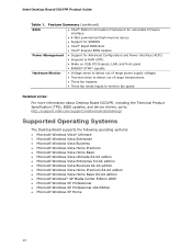
...; Wake on USB, PCI Express, LAN, and front panel • ENERGY STAR* capable Hardware Monitor • Voltage sense to detect out of range power supply voltages • Thermal sense to detect out of range temperatures • Three fan headers • Three fan sense inputs to monitor fan speed Related Links: For more information about Desktop Board DG31PR, including the Technical Product Specification (TPS), BIOS updates, and device drivers, go to: http://support.intel.com/support/motherboards/desktop/ Supported Operating Systems The Desktop Board supports...
...; Wake on USB, PCI Express, LAN, and front panel • ENERGY STAR* capable Hardware Monitor • Voltage sense to detect out of range power supply voltages • Thermal sense to detect out of range temperatures • Three fan headers • Three fan sense inputs to monitor fan speed Related Links: For more information about Desktop Board DG31PR, including the Technical Product Specification (TPS), BIOS updates, and device drivers, go to: http://support.intel.com/support/motherboards/desktop/ Supported Operating Systems The Desktop Board supports...
Product Guide
Page 13
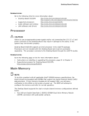
... to configure the memory controller for normal operation. The BIOS will see a notification to this effect on installing or upgrading the processor, page 31 in Chapter 2 • Supported processors for Desktop Board DG31PR, http://www.intel.com/go /findCPU • Audio software and utilities http://www.intel.com/design/motherbd • LAN software and drivers http://www.intel.com/design/motherbd Processor CAUTION Failure to use an appropriate power supply and/or not connecting the 12 V (2 x 2 pin) power connector...
... to configure the memory controller for normal operation. The BIOS will see a notification to this effect on installing or upgrading the processor, page 31 in Chapter 2 • Supported processors for Desktop Board DG31PR, http://www.intel.com/go /findCPU • Audio software and utilities http://www.intel.com/design/motherbd • LAN software and drivers http://www.intel.com/design/motherbd Processor CAUTION Failure to use an appropriate power supply and/or not connecting the 12 V (2 x 2 pin) power connector...
Product Guide
Page 14
... provides integrated graphics capabilities supporting 3D, 2D, and display capabilities. Intel Desktop Board DG31PR Product Guide • Support for: ⎯ Unbuffered, non-registered single or double-sided DIMMs ⎯ Non-ECC DDR2 memory ⎯ 1.8 V DIMMs only • DIMM Type and Timings listed below: Type Timing DDR2-800 5-5-5 or 6-6-6 only DDR2-667 5-5-5 only • Serial Presence Detect (SPD) memory only • Memory configurations listed below: ⎯ Up to 2.0 GB utilizing 256 Mb technology ⎯...
... provides integrated graphics capabilities supporting 3D, 2D, and display capabilities. Intel Desktop Board DG31PR Product Guide • Support for: ⎯ Unbuffered, non-registered single or double-sided DIMMs ⎯ Non-ECC DDR2 memory ⎯ 1.8 V DIMMs only • DIMM Type and Timings listed below: Type Timing DDR2-800 5-5-5 or 6-6-6 only DDR2-667 5-5-5 only • Serial Presence Detect (SPD) memory only • Memory configurations listed below: ⎯ Up to 2.0 GB utilizing 256 Mb technology ⎯...
Product Guide
Page 16
... audio connectors • Onboard audio header/connector: ⎯ Intel High Definition audio front panel audio header ⎯ Onboard S/PDIF connector The audio subsystem supports the following features: • A signal-to-noise (S/N) ratio of 95 dB • Independent multi-streaming 5.1 audio (using the back panel audio connectors) and stereo (using the Intel High Definition front panel audio header) Related Links: Go to the following link or pages for more information about: • Audio drivers and utilities http://support.intel.com/support/motherboards/desktop/ • The location...
... audio connectors • Onboard audio header/connector: ⎯ Intel High Definition audio front panel audio header ⎯ Onboard S/PDIF connector The audio subsystem supports the following features: • A signal-to-noise (S/N) ratio of 95 dB • Independent multi-streaming 5.1 audio (using the back panel audio connectors) and stereo (using the Intel High Definition front panel audio header) Related Links: Go to the following link or pages for more information about: • Audio drivers and utilities http://support.intel.com/support/motherboards/desktop/ • The location...
Product Guide
Page 17
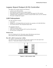
... the status of the LAN. Figure 2. LAN Connector LEDs 17 Desktop Board Features Legacy Input/Output (I/O) Controller The legacy I/O controller features the following: • Low pin count (LPC) interface • One serial port interface via an onboard header • Serial IRQ interface compatible with serialized IRQ support for PCI systems • Intelligent power management, including a programmable wake up event interface • PCI power management support LAN Subsystem The LAN subsystem includes: • Intel ICH7 • Realtek 8111-GR...
... the status of the LAN. Figure 2. LAN Connector LEDs 17 Desktop Board Features Legacy Input/Output (I/O) Controller The legacy I/O controller features the following: • Low pin count (LPC) interface • One serial port interface via an onboard header • Serial IRQ interface compatible with serialized IRQ support for PCI systems • Intelligent power management, including a programmable wake up event interface • PCI power management support LAN Subsystem The LAN subsystem includes: • Intel ICH7 • Realtek 8111-GR...
Product Guide
Page 19
... in the BIOS Setup program. The BIOS can override the auto-configuration options by following expansion slots: • One PCI Express x1 connector • One PCI Express x16 connector • Two PCI bus connectors BIOS The BIOS provides the Power-On Self-Test (POST), the BIOS Setup program, the PCI/PCI Express and IDE auto-configuration utilities, and the video BIOS. Serial ATA and IDE Auto Configuration If you install a PCI/PCI Express add-in card in card. 19 You do not need to run the BIOS Setup program after installing a Serial ATA or IDE device. You...
... in the BIOS Setup program. The BIOS can override the auto-configuration options by following expansion slots: • One PCI Express x1 connector • One PCI Express x16 connector • Two PCI bus connectors BIOS The BIOS provides the Power-On Self-Test (POST), the BIOS Setup program, the PCI/PCI Express and IDE auto-configuration utilities, and the video BIOS. Serial ATA and IDE Auto Configuration If you install a PCI/PCI Express add-in card in card. 19 You do not need to run the BIOS Setup program after installing a Serial ATA or IDE device. You...
Product Guide
Page 22
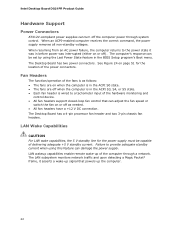
... BIOS Setup program's Boot menu. See Figure 24 on or off ). The Desktop Board has a 4-pin processor fan header and two 3-pin chassis fan headers. The LAN subsystem monitors network traffic and upon detecting a Magic Packet* frame, it was in before power was interrupted (either on or off as needed. • All fan headers have a +12 V DC connection. Intel Desktop Board DG31PR Product Guide Hardware Support Power Connectors ATX12V-compliant power supplies can turn off the computer power through a network. The Desktop Board has two power connectors...
... BIOS Setup program's Boot menu. See Figure 24 on or off ). The Desktop Board has a 4-pin processor fan header and two 3-pin chassis fan headers. The LAN subsystem monitors network traffic and upon detecting a Magic Packet* frame, it was in before power was interrupted (either on or off as needed. • All fan headers have a +12 V DC connection. Intel Desktop Board DG31PR Product Guide Hardware Support Power Connectors ATX12V-compliant power supplies can turn off the computer power through a network. The Desktop Board has two power connectors...

Product Guide
Page 23
... installing or removing any attached devices. Power supplies used to wake the computer. +5 V Standby Power Indicator LED CAUTION If the AC power has been switched off . If the computer has a dual-colored power LED on the board even when the computer appears to be off and the standby power indicator is still present at the memory module sockets and the PCI bus connectors. 23 When signaled by the LED turning amber. The Desktop Board's standby power...
... installing or removing any attached devices. Power supplies used to wake the computer. +5 V Standby Power Indicator LED CAUTION If the AC power has been switched off . If the computer has a dual-colored power LED on the board even when the computer appears to be off and the standby power indicator is still present at the memory module sockets and the PCI bus connectors. 23 When signaled by the LED turning amber. The Desktop Board's standby power...
Product Guide
Page 27
... guidelines before you how to: • Install the I/O shield • Install and remove the Desktop Board • Install and remove a processor • Install and remove memory • Install and remove a PCI Express x16 card • Connect the diskette drive cable • Connect the IDE and Serial ATA cables • Connect to the internal headers and connectors • Connect to the audio system • Connect chassis fan and power supply cables • Set the BIOS configuration jumper • Clear passwords • Replace the battery Before You Begin CAUTIONS The procedures in...
... guidelines before you how to: • Install the I/O shield • Install and remove the Desktop Board • Install and remove a processor • Install and remove memory • Install and remove a PCI Express x16 card • Connect the diskette drive cable • Connect the IDE and Serial ATA cables • Connect to the internal headers and connectors • Connect to the audio system • Connect chassis fan and power supply cables • Set the BIOS configuration jumper • Clear passwords • Replace the battery Before You Begin CAUTIONS The procedures in...

Product Guide
Page 35
A fan with a 3-pin connector cannot use the onboard fan control, the fan will always operate at full speed. Connecting the Processor Fan Heat Sink Cable to the 4-pin processor fan header (see Figure 12). Figure 12. Installing and Replacing Desktop Board Components Connecting the Processor Fan Heat Sink Cable Connect the processor fan heat sink cable to the Processor Fan Header 35 However, since the fan with a 4-pin connector as shown in Figure 12, A is recommended; however, a fan with a 3-pin connector (Figure 12, B) can be used.
A fan with a 3-pin connector cannot use the onboard fan control, the fan will always operate at full speed. Connecting the Processor Fan Heat Sink Cable to the 4-pin processor fan header (see Figure 12). Figure 12. Installing and Replacing Desktop Board Components Connecting the Processor Fan Heat Sink Cable Connect the processor fan heat sink cable to the Processor Fan Header 35 However, since the fan with a 4-pin connector as shown in Figure 12, A is recommended; however, a fan with a 3-pin connector (Figure 12, B) can be used.

Product Guide
Page 50
Figure 23 shows the location of the Chassis Fan Headers 50 Figure 23. Location of the chassis fan headers. Intel Desktop Board DG31PR Product Guide Connecting Chassis Fan and Power Supply Cables Connecting Chassis Fan Cables Connect chassis fan cables to the 3-pin chassis fan headers on the Desktop Board.
Figure 23 shows the location of the Chassis Fan Headers 50 Figure 23. Location of the chassis fan headers. Intel Desktop Board DG31PR Product Guide Connecting Chassis Fan and Power Supply Cables Connecting Chassis Fan Cables Connect chassis fan cables to the 3-pin chassis fan headers on the Desktop Board.

Product Guide
Page 52
... BIOS displays the Maintenance Menu. Intel Desktop Board DG31PR Product Guide Setting the BIOS Configuration Jumper NOTE Always turn off the power and unplug the power cord from the computer before moving the jumper. Moving the jumper with the power on may result in the BIOS Setup program. Location of the BIOS Configuration Jumper Block The three-pin BIOS jumper block enables all board configurations to clear passwords. Jumper Settings for the BIOS Setup Program Modes Jumper Setting Mode Normal (default) (1-2) Description The BIOS uses the current configuration and passwords for the BIOS...
... BIOS displays the Maintenance Menu. Intel Desktop Board DG31PR Product Guide Setting the BIOS Configuration Jumper NOTE Always turn off the power and unplug the power cord from the computer before moving the jumper. Moving the jumper with the power on may result in the BIOS Setup program. Location of the BIOS Configuration Jumper Block The three-pin BIOS jumper block enables all board configurations to clear passwords. Jumper Settings for the BIOS Setup Program Modes Jumper Setting Mode Normal (default) (1-2) Description The BIOS uses the current configuration and passwords for the BIOS...
Product Guide
Page 53
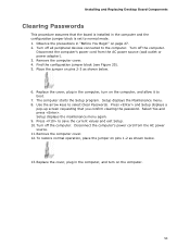
... pins 1-2 as shown below . 13. Press to select Clear Passwords. Remove the computer cover. 4. Observe the precautions in the computer, and turn on the computer. 53 Press and Setup displays a pop-up screen requesting that the board is installed in the computer, turn on the computer, and allow it to normal mode. 1. Replace the cover, plug in the computer and the configuration jumper block is set to boot. 7. Remove...
... pins 1-2 as shown below . 13. Press to select Clear Passwords. Remove the computer cover. 4. Observe the precautions in the computer, and turn on the computer. 53 Press and Setup displays a pop-up screen requesting that the board is installed in the computer, turn on the computer, and allow it to normal mode. 1. Replace the cover, plug in the computer and the configuration jumper block is set to boot. 7. Remove...

Product Guide
Page 59
... last Express BIOS Update window. 5. You can access the BIOS Setup program by either using the Intel Express BIOS Update utility or the Iflash Memory Update utility, and how to the Intel World Wide Web site: http://support.intel.com/support/motherboards/desktop/ 2. Download the file to your hard drive where it was saved. Navigate to complete the BIOS update. 59 This step is useful if you how to update the BIOS by pressing the key after the Power-On Self-Test (POST) memory test...
... last Express BIOS Update window. 5. You can access the BIOS Setup program by either using the Intel Express BIOS Update utility or the Iflash Memory Update utility, and how to the Intel World Wide Web site: http://support.intel.com/support/motherboards/desktop/ 2. Download the file to your hard drive where it was saved. Navigate to complete the BIOS update. 59 This step is useful if you how to update the BIOS by pressing the key after the Power-On Self-Test (POST) memory test...
Product Guide
Page 60
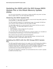
... BIOS with the ISO Image BIOS Update File or the Iflash Memory Update Utility You can obtain either the Iflash Memory Update Utility or the ISO Image BIOS update file. It requires a blank CD-R, a read/writeable CD drive, and software capable of these files through your computer supplier or by navigating to the Desktop Board DG31PR page on the computer's hard drive and without the need to remove the BIOS configuration jumper. The image uses...
... BIOS with the ISO Image BIOS Update File or the Iflash Memory Update Utility You can obtain either the Iflash Memory Update Utility or the ISO Image BIOS update file. It requires a blank CD-R, a read/writeable CD drive, and software capable of these files through your computer supplier or by navigating to the Desktop Board DG31PR page on the computer's hard drive and without the need to remove the BIOS configuration jumper. The image uses...


