
Product Specification
Page 5
... 11 1.1.3 Board Layout 12 1.1.4 Block Diagram 14 1.2 Online Support ...15 1.3 Processor ...15 1.4 System Memory ...16 1.4.1 Memory Configurations 17 1.5 Intel® 945G Chipset ...21 1.5.1 Intel 945G Graphics Subsystem 21 1.5.2 USB ...23 1.5.3 IDE Support 24 1.5.4 Real-Time Clock, CMOS SRAM, and Battery 26 1.6 PCI Express* Connectors 26 1.7 IEEE-1394a Connectors (Optional 26 1.8 Legacy I/O Controller 27 1.8.1 Serial Port...27 1.8.2 Parallel Port 27 1.8.3 Diskette Drive Controller 27 1.8.4 Keyboard and Mouse Interface 27 1.9 Audio Subsystem ...28 1.9.1 Audio Subsystem Software 28...
... 11 1.1.3 Board Layout 12 1.1.4 Block Diagram 14 1.2 Online Support ...15 1.3 Processor ...15 1.4 System Memory ...16 1.4.1 Memory Configurations 17 1.5 Intel® 945G Chipset ...21 1.5.1 Intel 945G Graphics Subsystem 21 1.5.2 USB ...23 1.5.3 IDE Support 24 1.5.4 Real-Time Clock, CMOS SRAM, and Battery 26 1.6 PCI Express* Connectors 26 1.7 IEEE-1394a Connectors (Optional 26 1.8 Legacy I/O Controller 27 1.8.1 Serial Port...27 1.8.2 Parallel Port 27 1.8.3 Diskette Drive Controller 27 1.8.4 Keyboard and Mouse Interface 27 1.9 Audio Subsystem ...28 1.9.1 Audio Subsystem Software 28...

Product Specification
Page 6
...Statement 76 2.15.4 Recycling Considerations 77 2.15.5 Product Certification Markings (Board Level 78 3 Overview of BIOS Features 3.1 Introduction ...79 3.2 BIOS Flash Memory Organization 80 3.3 Resource Configuration 80 3.3.1 PCI Autoconfiguration 80 3.3.2 PCI IDE Support 80 3.4 System Management BIOS (SMBIOS 81 3.5 Legacy USB Support...81 3.6 BIOS Updates ...82 3.6.1 Language Support 82 3.6.2 Custom Splash Screen 82 3.7 Boot Options ...83 3.7.1 CD-ROM Boot 83 3.7.2 Network Boot 83 3.7.3 Booting Without Attached Devices 83 3.7.4 Changing the Default Boot Device During POST 83 vi
...Statement 76 2.15.4 Recycling Considerations 77 2.15.5 Product Certification Markings (Board Level 78 3 Overview of BIOS Features 3.1 Introduction ...79 3.2 BIOS Flash Memory Organization 80 3.3 Resource Configuration 80 3.3.1 PCI Autoconfiguration 80 3.3.2 PCI IDE Support 80 3.4 System Management BIOS (SMBIOS 81 3.5 Legacy USB Support...81 3.6 BIOS Updates ...82 3.6.1 Language Support 82 3.6.2 Custom Splash Screen 82 3.7 Boot Options ...83 3.7.1 CD-ROM Boot 83 3.7.2 Network Boot 83 3.7.3 Booting Without Attached Devices 83 3.7.4 Changing the Default Boot Device During POST 83 vi

Product Specification
Page 7
...4.1 Speaker ...87 4.2 BIOS Beep Codes...87 4.3 BIOS Error Messages 87 4.4 Port 80h POST Codes 88 Figures 1. Memory Channel and DIMM Configuration 17 4. Connection Diagram for Front Panel USB Connectors 64 23. Connection Diagram for Front Panel Connector 62 22. Location of the Standby Power Indicator LED 44 17. Localized High Temperature Zones 72 vii Connection Diagram for 8-Channel (7.1) Audio Subsystem 54 19. Back Panel Connectors for IEEE 1394a Connectors 64 24. Detailed System Memory Address Map 46 18. Board Dimensions...66 26. Processor Heatsink for...
...4.1 Speaker ...87 4.2 BIOS Beep Codes...87 4.3 BIOS Error Messages 87 4.4 Port 80h POST Codes 88 Figures 1. Memory Channel and DIMM Configuration 17 4. Connection Diagram for Front Panel USB Connectors 64 23. Connection Diagram for Front Panel Connector 62 22. Location of the Standby Power Indicator LED 44 17. Localized High Temperature Zones 72 vii Connection Diagram for 8-Channel (7.1) Audio Subsystem 54 19. Back Panel Connectors for IEEE 1394a Connectors 64 24. Detailed System Memory Address Map 46 18. Board Dimensions...66 26. Processor Heatsink for...
Product Specification
Page 8
... the Power Switch 38 8. Component-side Connectors Shown in Figure 19 55 18. SCSI Hard Drive Activity LED Connector (Optional 58 22. BIOS Setup Configuration Jumper Settings 65 32. Typical Port 80h POST Sequence 92 viii LAN Connector LED States 33 7. Power States and Targeted System Power 39 9. Interrupts ...50 15. Processor Fan Connector 59 24. Environmental Specifications 74 36. EMC Regulations ...75 38. BIOS Setup Program Function Keys 80 41. Port 80h POST Codes 89 47. Intel Desktop Board D945GTP Technical Product Specification Tables 1. PCI...
... the Power Switch 38 8. Component-side Connectors Shown in Figure 19 55 18. SCSI Hard Drive Activity LED Connector (Optional 58 22. BIOS Setup Configuration Jumper Settings 65 32. Typical Port 80h POST Sequence 92 viii LAN Connector LED States 33 7. Power States and Targeted System Power 39 9. Interrupts ...50 15. Processor Fan Connector 59 24. Environmental Specifications 74 36. EMC Regulations ...75 38. BIOS Setup Program Function Keys 80 41. Port 80h POST Codes 89 47. Intel Desktop Board D945GTP Technical Product Specification Tables 1. PCI...

Product Specification
Page 10
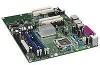
Intel Desktop Board D945GTP Technical Product Specification 1.1 Overview 1.1.1 Feature Summary Table 1 summarizes the major features of range thermal values • Three fan connectors • Three fan sense inputs used to detect out of the board. Table 1. BIOS • Intel® BIOS (resident in the SPI Flash device) • Support for Advanced Configuration and Power Interface (ACPI), Plug and Play, and SMBIOS Expansion Capabilities • Two PCI Conventional* bus connectors • One PCI Express* x1 bus add-in...
Intel Desktop Board D945GTP Technical Product Specification 1.1 Overview 1.1.1 Feature Summary Table 1 summarizes the major features of range thermal values • Three fan connectors • Three fan sense inputs used to detect out of the board. Table 1. BIOS • Intel® BIOS (resident in the SPI Flash device) • Support for Advanced Configuration and Power Interface (ACPI), Plug and Play, and SMBIOS Expansion Capabilities • Two PCI Conventional* bus connectors • One PCI Express* x1 bus add-in...

Product Specification
Page 14
.../2 Keyboard Diskette Drive Connector Intel 82801G I/O Controller Hub (ICH7) Serial Peripheral Interface (SPI) Flash Device DMI Interconnect High Definition Audio Link LAN Connect Interface VGA Port Channel A DIMMs (2) Display Interface Dual-Channel Memory Bus SMBus Channel B DIMMs (2) IEEE-1394a Connectors (optional) IEEE-1394a Controller (optional) PCI Bus LPC TPM Component Bus (Optional) 10/100 LAN PLC (Optional) LAN Connector Serial ATA IDE Interface Serial ATA IDE Connectors (4) PCI Slot 1 PCI Slot 2 PCI Bus SMBus Hardware Monitoring and Fan Control ASIC = connector or...
.../2 Keyboard Diskette Drive Connector Intel 82801G I/O Controller Hub (ICH7) Serial Peripheral Interface (SPI) Flash Device DMI Interconnect High Definition Audio Link LAN Connect Interface VGA Port Channel A DIMMs (2) Display Interface Dual-Channel Memory Bus SMBus Channel B DIMMs (2) IEEE-1394a Connectors (optional) IEEE-1394a Controller (optional) PCI Bus LPC TPM Component Bus (Optional) 10/100 LAN PLC (Optional) LAN Connector Serial ATA IDE Interface Serial ATA IDE Connectors (4) PCI Slot 1 PCI Slot 2 PCI Bus SMBus Hardware Monitoring and Fan Control ASIC = connector or...

Product Specification
Page 16
... is possible to install four 2048 MB (2 GB) modules for additional information on page 45 for optimum performance. Refer to correctly configure the memory settings, but performance and reliability may be populated with x16 organization are not supported. • 4 GB maximum total system memory. Intel Desktop Board D945GTP Technical Product Specification 1.4 System Memory The board has four DIMM sockets and support the following memory features: •...
... is possible to install four 2048 MB (2 GB) modules for additional information on page 45 for optimum performance. Refer to correctly configure the memory settings, but performance and reliability may be populated with x16 organization are not supported. • 4 GB maximum total system memory. Intel Desktop Board D945GTP Technical Product Specification 1.4 System Memory The board has four DIMM sockets and support the following memory features: •...
Product Specification
Page 22
... additional system memory is installed. NOTE The use of DVMT requires operating system driver support. 22 Intel Desktop Board D945GTP Technical Product Specification • Video ⎯ Hardware motion compensation for MPEG2 ⎯ Software DVD at 30 fps full screen • Display ⎯ Integrated 24-bit 400 MHz RAMDAC ⎯ Up to 2048 x 1536 at 85 Hz (with ADD2/ADD2+) ⎯ Two multiplexed DVO port interfaces with legacy applications.
... additional system memory is installed. NOTE The use of DVMT requires operating system driver support. 22 Intel Desktop Board D945GTP Technical Product Specification • Video ⎯ Hardware motion compensation for MPEG2 ⎯ Software DVD at 30 fps full screen • Display ⎯ Integrated 24-bit 400 MHz RAMDAC ⎯ Up to 2048 x 1536 at 85 Hz (with ADD2/ADD2+) ⎯ Two multiplexed DVO port interfaces with legacy applications.

Product Specification
Page 24
... each port for configurations using the transfer modes. Intel Desktop Board D945GTP Technical Product Specification 1.5.3 IDE Support The board provides five IDE interface connectors: • One parallel ATA IDE connector that supports two devices • Four serial ATA IDE connectors that support one device per port. NOTE ATA-66 and ATA-100 are assigned (IRQ 14 and 15). ATA-66 protocol is similar to device connections, unlike Parallel ATA IDE which supports a master/slave configuration and two devices per channel. The drive...
... each port for configurations using the transfer modes. Intel Desktop Board D945GTP Technical Product Specification 1.5.3 IDE Support The board provides five IDE interface connectors: • One parallel ATA IDE connector that supports two devices • Four serial ATA IDE connectors that support one device per port. NOTE ATA-66 and ATA-100 are assigned (IRQ 14 and 15). ATA-66 protocol is similar to device connections, unlike Parallel ATA IDE which supports a master/slave configuration and two devices per channel. The drive...

Product Specification
Page 25
...-voltage power connectors. RAID Level 5 stripes data at a block level across all mirrored sets. For information about The location of Independent Drives) levels: • RAID 0 - Multiple physical drives maintain duplicate sets of parity. • RAID 5 - data striping and mirroring. For more than other RAID types. Because parity data is devoted to create one logical drive. Product Description NOTE Many Serial ATA drives use the same LED as the onboard IDE controller...
...-voltage power connectors. RAID Level 5 stripes data at a block level across all mirrored sets. For information about The location of Independent Drives) levels: • RAID 0 - Multiple physical drives maintain duplicate sets of parity. • RAID 5 - data striping and mirroring. For more than other RAID types. Because parity data is devoted to create one logical drive. Product Description NOTE Many Serial ATA drives use the same LED as the onboard IDE controller...

Product Specification
Page 31
... Ethernet LAN connectivity • Full device driver compatibility • Programmable transit threshold • Configuration EEPROM that supports the 82562GX and 82562GZ • PCI Conventional bus power management ⎯ Supports ACPI technology ⎯ Supports LAN wake capabilities 1.10.1 LAN Subsystem Software LAN software and drivers are available from Intel's World Wide Web site. As a manufacturing option, the board includes one of the following LAN devices: ⎯ Intel 82562GX/82562GZ PLC for 10/100 Mbits/sec Ethernet LAN connectivity ⎯ Intel 82573E...
... Ethernet LAN connectivity • Full device driver compatibility • Programmable transit threshold • Configuration EEPROM that supports the 82562GX and 82562GZ • PCI Conventional bus power management ⎯ Supports ACPI technology ⎯ Supports LAN wake capabilities 1.10.1 LAN Subsystem Software LAN software and drivers are available from Intel's World Wide Web site. As a manufacturing option, the board includes one of the following LAN devices: ⎯ Intel 82562GX/82562GZ PLC for 10/100 Mbits/sec Ethernet LAN connectivity ⎯ Intel 82573E...

Product Specification
Page 46
... system memory map. Intel Desktop Board D945GTP Technical Product Specification • MCH base address registers, internal graphics ranges, PCI Express ports (up to 512 MB) • Memory-mapped I/O that is no overlap of system addresses. 4 GB Top of System Address Space FLASH APIC Reserved ~20 MB PCI Memory Range contains PCI, chipsets, Direct Media Interface (DMI), and ICH ranges (approximately 750 MB) DRAM Range DOS Compatibility Memory Top of usable DRAM (memory...
... system memory map. Intel Desktop Board D945GTP Technical Product Specification • MCH base address registers, internal graphics ranges, PCI Express ports (up to 512 MB) • Memory-mapped I/O that is no overlap of system addresses. 4 GB Top of System Address Space FLASH APIC Reserved ~20 MB PCI Memory Range contains PCI, chipsets, Direct Media Interface (DMI), and ICH ranges (approximately 750 MB) DRAM Range DOS Compatibility Memory Top of usable DRAM (memory...

Product Specification
Page 49
...00 00 Description Memory controller of Intel 82945G component PCI Express x16 graphics port (Note 1) Integrated graphics controller Intel High Definition Audio Controller PCI Express port 1 PCI Express port 2 PCI Express port 3 PCI Express port 4 USB UHCI controller 1 USB UHCI controller 2 USB UHCI controller 3 USB UHCI controller 4 EHCI controller PCI bridge PCI controller Parallel ATA IDE controller Serial ATA controller SMBus controller Gigabit LAN controller (if present) PCI Conventional bus connector 1 PCI Conventional bus connector 2 IEEE-1394a controller (if present) Intel 82562 10/100...
...00 00 Description Memory controller of Intel 82945G component PCI Express x16 graphics port (Note 1) Integrated graphics controller Intel High Definition Audio Controller PCI Express port 1 PCI Express port 2 PCI Express port 3 PCI Express port 4 USB UHCI controller 1 USB UHCI controller 2 USB UHCI controller 3 USB UHCI controller 4 EHCI controller PCI bridge PCI controller Parallel ATA IDE controller Serial ATA controller SMBus controller Gigabit LAN controller (if present) PCI Conventional bus connector 1 PCI Conventional bus connector 2 IEEE-1394a controller (if present) Intel 82562 10/100...

Product Specification
Page 53
... panel USB, front panel USB, and PS/2. Do not use these groups: • Back panel I/O connectors (see page 55) • Component-side I/O connectors (see page 53) 2.8.1 Back Panel Connectors The back panel configuration is dependent upon which audio subsystem is present. The other internal connectors are as fans and internal peripherals. The configurations are not overcurrent protected and should connect only to the computer, the power cable, and the external devices themselves...
... panel USB, front panel USB, and PS/2. Do not use these groups: • Back panel I/O connectors (see page 55) • Component-side I/O connectors (see page 53) 2.8.1 Back Panel Connectors The back panel configuration is dependent upon which audio subsystem is present. The other internal connectors are as fans and internal peripherals. The configurations are not overcurrent protected and should connect only to the computer, the power cable, and the external devices themselves...
Product Specification
Page 79
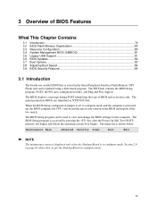
..., POST, the PCI auto-configuration utility, and Plug and Play support. The BIOS displays a message during POST identifying the type of BIOS Features What This Chapter Contains 3.1 Introduction ...79 3.2 BIOS Flash Memory Organization 80 3.3 Resource Configuration 80 3.4 System Management BIOS (SMBIOS 81 3.5 Legacy USB Support...81 3.6 BIOS Updates ...82 3.7 Boot Options ...83 3.8 Adjusting Boot Speed 84 3.9 BIOS Security Features 85 3.1 Introduction The boards use an Intel BIOS that is stored in the Serial Peripheral Interface Flash Memory (SPI Flash) and can be updated using a disk...
..., POST, the PCI auto-configuration utility, and Plug and Play support. The BIOS displays a message during POST identifying the type of BIOS Features What This Chapter Contains 3.1 Introduction ...79 3.2 BIOS Flash Memory Organization 80 3.3 Resource Configuration 80 3.4 System Management BIOS (SMBIOS 81 3.5 Legacy USB Support...81 3.6 BIOS Updates ...82 3.7 Boot Options ...83 3.8 Adjusting Boot Speed 84 3.9 BIOS Security Features 85 3.1 Introduction The boards use an Intel BIOS that is stored in the Serial Peripheral Interface Flash Memory (SPI Flash) and can be updated using a disk...
Product Specification
Page 80
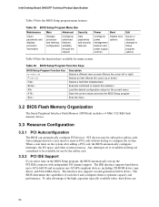
...devices. The BIOS determines the capabilities of the high capacities typically available today, hard drives are considered to be onboard or add-in Setup are 80 The interface also supports second-generation SATA drives. Intel Desktop Board D945GTP Technical Product Specification Table 39 lists the BIOS Setup program menu features. When a user turns on the system after adding a PCI card, the BIOS automatically configures interrupts, the I /O channel support. BIOS Setup Program Function Keys BIOS Setup Program Function Key or or Description Selects a different menu screen...
...devices. The BIOS determines the capabilities of the high capacities typically available today, hard drives are considered to be onboard or add-in Setup are 80 The interface also supports second-generation SATA drives. Intel Desktop Board D945GTP Technical Product Specification Table 39 lists the BIOS Setup program menu features. When a user turns on the system after adding a PCI card, the BIOS automatically configures interrupts, the I /O channel support. BIOS Setup Program Function Keys BIOS Setup Program Function Key or or Description Selects a different menu screen...
Product Specification
Page 81
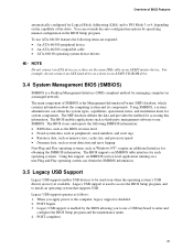
... managing computers in the BIOS Setup program. Legacy USB support is disabled. 2. Legacy USB support operates as Windows NT*, require an additional interface for system components. POST completes. 81 POST begins. 3. Using SMBIOS, a system administrator can override the auto-configuration options by the BIOS allowing you apply power to enter and configure the BIOS Setup program and the maintenance menu. 4. You can obtain the system types, capabilities, operational status, and installation dates for obtaining the...
... managing computers in the BIOS Setup program. Legacy USB support is disabled. 2. Legacy USB support operates as Windows NT*, require an additional interface for system components. POST completes. 81 POST begins. 3. Using SMBIOS, a system administrator can override the auto-configuration options by the BIOS allowing you apply power to enter and configure the BIOS Setup program and the maintenance menu. 4. You can obtain the system types, capabilities, operational status, and installation dates for obtaining the...

Product Specification
Page 84
... of painting complex graphic images and changing video modes. Some monitors initialize and communicate with the BIOS more quickly, which eliminates display of the logo splash screen. In the Boot Menu: • Set the hard disk drive as the first boot device. This can also contribute to a boot time that the Intel logo screen (or a custom logo splash screen) will not be used. In the Peripheral Configuration submenu, disable the LAN device if it is...
... of painting complex graphic images and changing video modes. Some monitors initialize and communicate with the BIOS more quickly, which eliminates display of the logo splash screen. In the Boot Menu: • Set the hard disk drive as the first boot device. This can also contribute to a boot time that the Intel logo screen (or a custom logo splash screen) will not be used. In the Peripheral Configuration submenu, disable the LAN device if it is...

Product Specification
Page 88
Intel Desktop Board D945GTP Technical Product Specification 4.4 Port 80h POST Codes During the POST, the BIOS generates diagnostic progress codes (POST-codes) to I /O Busses: PCI, USB, ISA, ATA, etc. 5F is an unrecoverable error. Displaying the POST-codes requires a PCI bus add-in hexadecimal. FF Category/Subsystem Debug codes: Can be installed in PCI bus connector 1. Recovery: 3F indicated recovery failure. Input devices: Keyboard/Mouse. 9F is an unrecoverable error. Boot Devices: Includes fixed media and removable media. BF is an unrecoverable error. E0 - The POST card ...
Intel Desktop Board D945GTP Technical Product Specification 4.4 Port 80h POST Codes During the POST, the BIOS generates diagnostic progress codes (POST-codes) to I /O Busses: PCI, USB, ISA, ATA, etc. 5F is an unrecoverable error. Displaying the POST-codes requires a PCI bus add-in hexadecimal. FF Category/Subsystem Debug codes: Can be installed in PCI bus connector 1. Recovery: 3F indicated recovery failure. Input devices: Keyboard/Mouse. 9F is an unrecoverable error. Boot Devices: Includes fixed media and removable media. BF is an unrecoverable error. E0 - The POST card ...

Product Specification
Page 89
... the memory controller and the DIMMs Configuring memory Optimizing memory settings Initializing memory, such as ECC init Testing memory PCI Bus Enumerating PCI busses Allocating resources to PCI bus Hot Plug PCI controller initialization Reserved for PCI Bus USB Resetting USB bus Reserved for USB ATA/ATAPI/SATA Resetting PATA/SATA bus and all devices Reserved for ATA SMBus Resetting SMBUS Reserved for SMBUS Local Console Resetting the VGA controller Disabling the VGA controller Enabling the VGA controller Remote Console Resetting the console controller Disabling the console controller Enabling...
... the memory controller and the DIMMs Configuring memory Optimizing memory settings Initializing memory, such as ECC init Testing memory PCI Bus Enumerating PCI busses Allocating resources to PCI bus Hot Plug PCI controller initialization Reserved for PCI Bus USB Resetting USB bus Reserved for USB ATA/ATAPI/SATA Resetting PATA/SATA bus and all devices Reserved for ATA SMBus Resetting SMBUS Reserved for SMBUS Local Console Resetting the VGA controller Disabling the VGA controller Enabling the VGA controller Remote Console Resetting the console controller Disabling the console controller Enabling...


