

Product Specification
Page 5
... Summary 12 1.3.2 Manufacturing Options 13 1.3.3 Board Layouts 14 1.3.4 Block Diagram 18 1.4 Online Support ...19 1.5 Processor ...19 1.6 System Memory ...20 1.6.1 Memory Configurations 22 1.7 Intel® 915P Chipset...26 1.7.1 USB ...26 1.7.2 IDE Support 26 1.7.3 Real-Time Clock, CMOS SRAM, and...Controller 29 1.9.4 Keyboard and Mouse Interface 30 1.10 Audio Subsystem ...30 1.10.1 Audio Subsystem Software 30 1.10.2 Audio Connectors 30 1.10.3 Intel® High Definition Audio Subsystem 31 1.11 LAN Subsystem ...32 1.11.1 Intel® 82562EZ Physical Layer Interface Device 32 1.11.2...
... Summary 12 1.3.2 Manufacturing Options 13 1.3.3 Board Layouts 14 1.3.4 Block Diagram 18 1.4 Online Support ...19 1.5 Processor ...19 1.6 System Memory ...20 1.6.1 Memory Configurations 22 1.7 Intel® 915P Chipset...26 1.7.1 USB ...26 1.7.2 IDE Support 26 1.7.3 Real-Time Clock, CMOS SRAM, and...Controller 29 1.9.4 Keyboard and Mouse Interface 30 1.10 Audio Subsystem ...30 1.10.1 Audio Subsystem Software 30 1.10.2 Audio Connectors 30 1.10.3 Intel® High Definition Audio Subsystem 31 1.11 LAN Subsystem ...32 1.11.1 Intel® 82562EZ Physical Layer Interface Device 32 1.11.2...

Product Specification
Page 7
...Diagram...18 4. Dual Channel (Interleaved) Mode Configuration with Intel® Rapid BIOS Boot 96 3.8.1 Peripheral Selection and Configuration 96 3.8.2 Intel Rapid BIOS Boot 96 3.9 BIOS Security Features 97 4...Front Panel USB Connectors 76 22. Connection Diagram for Front Panel Connector 74 21. Processor Heatsink for IEEE 1394a Connectors 76 23. D915PGN Board Components 14 2. Dual Channel.... Memory Channel and DIMM Configuration 22 5. Thermal Monitoring for High Definition Audio Subsystem...... 31 11. LAN Connector LED Locations 33 13. Location of the Standby Power Indicator LED...
...Diagram...18 4. Dual Channel (Interleaved) Mode Configuration with Intel® Rapid BIOS Boot 96 3.8.1 Peripheral Selection and Configuration 96 3.8.2 Intel Rapid BIOS Boot 96 3.9 BIOS Security Features 97 4...Front Panel USB Connectors 76 22. Connection Diagram for Front Panel Connector 74 21. Processor Heatsink for IEEE 1394a Connectors 76 23. D915PGN Board Components 14 2. Dual Channel.... Memory Channel and DIMM Configuration 22 5. Thermal Monitoring for High Definition Audio Subsystem...... 31 11. LAN Connector LED Locations 33 13. Location of the Standby Power Indicator LED...
Product Specification
Page 8
...Front Panel Audio Connector 70 24. Chassis Intrusion Connector 70 26. SCSI Hard Drive Activity LED Connector (Optional 71 27. Processor Fan Connector ...71 29. Alternate Power Connector 73 33. DC Loading Characteristics 81 39. Safety Regulations ...87 43. Feature Summary ...12 3. D915PSY Board Components Shown in Figure 1 15 5. Supported Memory Configurations 21 8. LAN...Setup Configuration Jumper Settings 77 38. Environmental Specifications 86 42. Intel Desktop Board D915PGN/D915PSY Technical Product Specification 28. Localized High Temperature...
...Front Panel Audio Connector 70 24. Chassis Intrusion Connector 70 26. SCSI Hard Drive Activity LED Connector (Optional 71 27. Processor Fan Connector ...71 29. Alternate Power Connector 73 33. DC Loading Characteristics 81 39. Safety Regulations ...87 43. Feature Summary ...12 3. D915PSY Board Components Shown in Figure 1 15 5. Supported Memory Configurations 21 8. LAN...Setup Configuration Jumper Settings 77 38. Environmental Specifications 86 42. Intel Desktop Board D915PGN/D915PSY Technical Product Specification 28. Localized High Temperature...

Product Specification
Page 11
... This Chapter Contains 1.1 PCI Bus Terminology Change 11 1.2 Board Differences ...11 1.3 Overview ...12 1.4 Online Support ...19 1.5 Processor ...19 1.6 System Memory ...20 1.7 Intel® 915P Chipset...26 1.8 PCI Express Connectors 28 1.9 I/O Controller...29 1.10 Audio Subsystem ...30 1.11 LAN Subsystem ...32 1.12 Hardware Management Subsystem 34 1.13 Power Management ...38 1.14 Trusted Platform Module (Optional...
... This Chapter Contains 1.1 PCI Bus Terminology Change 11 1.2 Board Differences ...11 1.3 Overview ...12 1.4 Online Support ...19 1.5 Processor ...19 1.6 System Memory ...20 1.7 Intel® 915P Chipset...26 1.8 PCI Express Connectors 28 1.9 I/O Controller...29 1.10 Audio Subsystem ...30 1.11 LAN Subsystem ...32 1.12 Hardware Management Subsystem 34 1.13 Power Management ...38 1.14 Trusted Platform Module (Optional...

Product Specification
Page 12
... Processor Memory Chipset Video Audio I/O Control USB Peripheral Interfaces LAN Support BIOS • D915PGN: ATX (12.00 inches by 9.60 inches [304.80 millimeters by 243.84 millimeters]) • D915PSY: microATX Form Factor (9.60 inches by 9.60 inches [243.84 millimeters by 243.84 millimeters]) Support for an Intel® Pentium® 4 processor in an LGA775...
... Processor Memory Chipset Video Audio I/O Control USB Peripheral Interfaces LAN Support BIOS • D915PGN: ATX (12.00 inches by 9.60 inches [304.80 millimeters by 243.84 millimeters]) • D915PSY: microATX Form Factor (9.60 inches by 9.60 inches [243.84 millimeters by 243.84 millimeters]) Support for an Intel® Pentium® 4 processor in an LGA775...

Product Specification
Page 18
... Express x1 Interface DMI Interconnect High Definition Audio Link LAN Connect Interface LPC Bus PCI Express x1 Slot 1 PCI Express x1 Slot 2 D915PGN only Parallel ATA IDE Connector Parallel ATA IDE Interface LGA775 Processor Socket System Bus (800/533 MHz) PCI Express x16 Interface PCI Express x16 Connector Intel 82915P Memory Controller Hub (MCH) Channel...
... Express x1 Interface DMI Interconnect High Definition Audio Link LAN Connect Interface LPC Bus PCI Express x1 Slot 1 PCI Express x1 Slot 2 D915PGN only Parallel ATA IDE Connector Parallel ATA IDE Interface LGA775 Processor Socket System Bus (800/533 MHz) PCI Express x16 Interface PCI Express x16 Connector Intel 82915P Memory Controller Hub (MCH) Channel...
Product Specification
Page 19
... to Section 2.8.2.2, page 72 19 Supported processors for the D915PGN board Supported processors for a list of supported processors. Product Description 1.4 Online Support To find information about ... See the Intel web site listed below for the Desktop Board D915PSY Processor data sheets ICH6 addressing Custom splash screens Audio software and utilities LAN software and drivers Visit this World...
... to Section 2.8.2.2, page 72 19 Supported processors for the D915PGN board Supported processors for a list of supported processors. Product Description 1.4 Online Support To find information about ... See the Intel web site listed below for the Desktop Board D915PSY Processor data sheets ICH6 addressing Custom splash screens Audio software and utilities LAN software and drivers Visit this World...
Product Specification
Page 20
...interference with the memory retention mechanism. • To be fully compliant with x16 organization are not supported. • 4 GB maximum total system memory. Intel Desktop Board D915PGN/D915PSY Technical Product Specification 1.6 System Memory The boards have four DIMM sockets and support the following memory features: • 2.5 V ..., the board should be ... 800 MHz 800 or 533 MHz Note: When using an 800 MHz system bus frequency processor, DDR 333 memory is installed, the BIOS will attempt to accurately configure memory settings for information on the total amount of DIMM...
...interference with the memory retention mechanism. • To be fully compliant with x16 organization are not supported. • 4 GB maximum total system memory. Intel Desktop Board D915PGN/D915PSY Technical Product Specification 1.6 System Memory The boards have four DIMM sockets and support the following memory features: • 2.5 V ..., the board should be ... 800 MHz 800 or 533 MHz Note: When using an 800 MHz system bus frequency processor, DDR 333 memory is installed, the BIOS will attempt to accurately configure memory settings for information on the total amount of DIMM...

Product Specification
Page 26
... panel connectors adjacent to the audio connectors • Four ports are implemented with DMI interconnect • Firmware Hub (FWH) The MCH is attached to the cable. Intel Desktop Board D915PGN/D915PSY Technical Product Specification 1.7 Intel® 915P Chipset The Intel 915P chipset consists of the following modes: • Programmed I/O (PIO): processor controls data transfer. •...
... panel connectors adjacent to the audio connectors • Four ports are implemented with DMI interconnect • Firmware Hub (FWH) The MCH is attached to the cable. Intel Desktop Board D915PGN/D915PSY Technical Product Specification 1.7 Intel® 915P Chipset The Intel 915P chipset consists of the following modes: • Programmed I/O (PIO): processor controls data transfer. •...

Product Specification
Page 33
... with Integrated LEDs Two LEDs are built into the RJ-45 LAN connector (shown in PCI Conventional bus slot 2: • Monitoring of system firmware progress events, including: BIOS present Primary processor initialization Memory initialization Video initialization PCI resource ... boot devices • Reset, shutdown, power cycle, and power up and the 10/100 Mbits/sec LAN subsystem is operating. LAN link is not established. LAN Connector LED Locations Table 8 describes the LED states when the board is selected. 1.11.2 Alert Standard ...
... with Integrated LEDs Two LEDs are built into the RJ-45 LAN connector (shown in PCI Conventional bus slot 2: • Monitoring of system firmware progress events, including: BIOS present Primary processor initialization Memory initialization Video initialization PCI resource ... boot devices • Reset, shutdown, power cycle, and power up and the 10/100 Mbits/sec LAN subsystem is operating. LAN link is not established. LAN Connector LED Locations Table 8 describes the LED states when the board is selected. 1.11.2 Alert Standard ...

Product Specification
Page 34
...fan control ASIC include: • Internal ambient temperature sensor • Two remote thermal diode sensors for direct monitoring of processor temperature and ambient temperature sensing • Power supply monitoring of the fan connectors and sensors for thermal monitoring on Refer ... all three fans, that use an Intel® PRO/Wireless 2225BG add-in card. Intel Desktop Board D915PGN/D915PSY Technical Product Specification 1.11.3 LAN Subsystem Software LAN software and drivers are available from Intel's World Wide Web site. Intel Wireless Connect Technology features the following :...
...fan control ASIC include: • Internal ambient temperature sensor • Two remote thermal diode sensors for direct monitoring of processor temperature and ambient temperature sensing • Power supply monitoring of the fan connectors and sensors for thermal monitoring on Refer ... all three fans, that use an Intel® PRO/Wireless 2225BG add-in card. Intel Desktop Board D915PGN/D915PSY Technical Product Specification 1.11.3 LAN Subsystem Software LAN software and drivers are available from Intel's World Wide Web site. Intel Wireless Connect Technology features the following :...

Product Specification
Page 36
Thermal Monitoring for the D915PGN board. 13 3 1 A CB 4 1 D 13 1 3 Item A B C D E F G H HG F E OM17055 Description Thermal diode, located on processor die Remote ambient temperature sensor Ambient temperature sensor, internal to hardware monitoring and fan control ASIC Processor fan Rear chassis fan 1 Front chassis fan ATX fan (optional) Rear chassis fan 2 Figure 13. Intel Desktop Board D915PGN/D915PSY Technical Product Specification 1.12.2 Thermal Monitoring Figure 13 shows the location of the sensors and fan connectors for D915PGN Board 36
Thermal Monitoring for the D915PGN board. 13 3 1 A CB 4 1 D 13 1 3 Item A B C D E F G H HG F E OM17055 Description Thermal diode, located on processor die Remote ambient temperature sensor Ambient temperature sensor, internal to hardware monitoring and fan control ASIC Processor fan Rear chassis fan 1 Front chassis fan ATX fan (optional) Rear chassis fan 2 Figure 13. Intel Desktop Board D915PGN/D915PSY Technical Product Specification 1.12.2 Thermal Monitoring Figure 13 shows the location of the sensors and fan connectors for D915PGN Board 36

Product Specification
Page 37
... monitoring ASIC used with the Desktop Board. Product Description Figure 14 shows the location of monitoring and control is dependent on processor die Remote ambient temperature sensor Ambient temperature sensor, internal to Section 1.13.2.2, page 42 37 The level of the sensors and... fan connectors for D915PSY Board 1.12.3 Fan Monitoring Fan monitoring can be implemented using Intel® Desktop Utilities, LANDesk* software, or thirdparty software. For information about The functions of the fan connectors Refer to hardware monitoring...
... monitoring ASIC used with the Desktop Board. Product Description Figure 14 shows the location of monitoring and control is dependent on processor die Remote ambient temperature sensor Ambient temperature sensor, internal to Section 1.13.2.2, page 42 37 The level of the sensors and... fan connectors for D915PSY Board 1.12.3 Fan Monitoring Fan monitoring can be implemented using Intel® Desktop Utilities, LANDesk* software, or thirdparty software. For information about The functions of the fan connectors Refer to hardware monitoring...
Product Specification
Page 40
.... no power except for wake-up logic. Service can be performed safely. Dependent on the system configuration, including add-in the system. 40 mechanical off . Processor States C0 - Context not saved. working S1 - Targeted System Power (Note 1) Full power > 30 W 5 W < power < 52.5 W Power < 5 W (Note 2) Power < 5 W...G0 - D1, D2, D3 - D3 - Notes: 1. stop grant No power No power No power Device States D0 - Intel Desktop Board D915PGN/D915PSY Technical Product Specification Table 10 lists the power states supported by battery or external source. no power for ...
.... no power except for wake-up logic. Service can be performed safely. Dependent on the system configuration, including add-in the system. 40 mechanical off . Processor States C0 - Context not saved. working S1 - Targeted System Power (Note 1) Full power > 30 W 5 W < power < 52.5 W Power < 5 W (Note 2) Power < 5 W...G0 - D1, D2, D3 - D3 - Notes: 1. stop grant No power No power No power Device States D0 - Intel Desktop Board D915PGN/D915PSY Technical Product Specification Table 10 lists the power states supported by battery or external source. no power for ...

Product Specification
Page 42
Intel Desktop Board D915PGN/D915PSY Technical Product Specification Resume on Ring enables telephony devices to the power state it is wired to Figure 18, page 66 ... monitoring on the D915PGN board The location of the fan connectors and sensors for thermal monitoring on the D915PSY board The signal names of the processor fan connector The signal names of Resume on when the board is in the BIOS Setup program's Boot menu. When an ACPI-enabled system receives...
Intel Desktop Board D915PGN/D915PSY Technical Product Specification Resume on Ring enables telephony devices to the power state it is wired to Figure 18, page 66 ... monitoring on the D915PGN board The location of the fan connectors and sensors for thermal monitoring on the D915PSY board The signal names of the processor fan connector The signal names of Resume on when the board is in the BIOS Setup program's Boot menu. When an ACPI-enabled system receives...

Product Specification
Page 71
... to all chassis fan connectors for the chassis fan connectors. Serial ATA Connectors Pin Signal Name 1 Ground 2 TXP 3 TXN 4 Ground 5 RXN 6 RXP 7 Ground Table 28. Processor Fan Connector Pin Signal Name 1 Ground 2 +12 V 3 FAN_TACH 4 FAN_CONTROL 2.8.2.1 Chassis Fan Connectors The D915PGN board has three standard and one optional chassis fan connectors: •...
... to all chassis fan connectors for the chassis fan connectors. Serial ATA Connectors Pin Signal Name 1 Ground 2 TXP 3 TXN 4 Ground 5 RXN 6 RXP 7 Ground Table 28. Processor Fan Connector Pin Signal Name 1 Ground 2 +12 V 3 FAN_TACH 4 FAN_CONTROL 2.8.2.1 Chassis Fan Connectors The D915PGN board has three standard and one optional chassis fan connectors: •...

Product Specification
Page 72
This connector provides power directly to do so will be used on Intel Desktop boards. Failure to the processor voltage regulator and must always be unconnected. 72 In this configuration, use two connectors to provide power to the board: ...2 x 2 connector. a 1 x 4 connector. This connector is to use three connectors to provide power to 144 W of ATX12V power supplies with a 2 x 12 main power cable. Intel Desktop Board D915PGN/D915PSY Technical Product Specification 2.8.2.2 Power Supply Connectors The board has three power supply connectors: • Main power -
This connector provides power directly to do so will be used on Intel Desktop boards. Failure to the processor voltage regulator and must always be unconnected. 72 In this configuration, use two connectors to provide power to the board: ...2 x 2 connector. a 1 x 4 connector. This connector is to use three connectors to provide power to 144 W of ATX12V power supplies with a 2 x 12 main power cable. Intel Desktop Board D915PGN/D915PSY Technical Product Specification 2.8.2.2 Power Supply Connectors The board has three power supply connectors: • Main power -

Product Specification
Page 77
... location of the Jumper Block OM17061 Table 37. Table 37 describes the jumper settings for booting. A 3 recovery diskette is powered-up, the BIOS compares the processor version and the microcode version in the same location on . Configure 2-3 1 After the POST runs, Setup runs automatically. Always turn off the power and unplug...
... location of the Jumper Block OM17061 Table 37. Table 37 describes the jumper settings for booting. A 3 recovery diskette is powered-up, the BIOS compares the processor version and the microcode version in the same location on . Configure 2-3 1 After the POST runs, Setup runs automatically. Always turn off the power and unplug...

Product Specification
Page 81
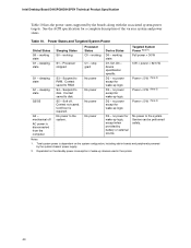
... model and not necessarily tied to an environment with a 500 mA current draw per USB port. This data is similar to a particular processor speed. Table 38. Technical Reference 2.11 Electrical Considerations 2.11.1 DC Loading Table 38 lists the DC loading characteristics of +5 V current for...must not exceed 8 A. 81 The total +5 V current draw for add-in cards. Maximum values assume a load placed on specific processor values or memory configurations but are designed to determine the overall system power requirements. These calculations are not based on the board that impact ...
... model and not necessarily tied to an environment with a 500 mA current draw per USB port. This data is similar to a particular processor speed. Table 38. Technical Reference 2.11 Electrical Considerations 2.11.1 DC Loading Table 38 lists the DC loading characteristics of +5 V current for...must not exceed 8 A. 81 The total +5 V current draw for add-in cards. Maximum values assume a load placed on specific processor values or memory configurations but are designed to determine the overall system power requirements. These calculations are not based on the board that impact ...

Product Specification
Page 82
...available only on configurations chosen by the integrator. System integrators should refer to a chassis fan connector. Fan Connector Current Capability Fan Connector Processor fan Front chassis fan Rear chassis fan Rear chassis fan 2 ATX fan (optional) Maximum Available Current 1000 mA 600 mA 600 ... current. Failure to a chassis fan connector may result in onboard component damage that will depend on the D915PGN board. Intel Desktop Board D915PGN/D915PSY Technical Product Specification 2.11.3 Fan Connector Current Capability CAUTION The processor fan must comply with the board.
...available only on configurations chosen by the integrator. System integrators should refer to a chassis fan connector. Fan Connector Current Capability Fan Connector Processor fan Front chassis fan Rear chassis fan Rear chassis fan 2 ATX fan (optional) Maximum Available Current 1000 mA 600 mA 600 ... current. Failure to a chassis fan connector may result in onboard component damage that will depend on the D915PGN board. Intel Desktop Board D915PGN/D915PSY Technical Product Specification 2.11.3 Fan Connector Current Capability CAUTION The processor fan must comply with the board.


