

Product Specification
Page 5
...1.1 PCI Bus Terminology Change 11 1.2 Board Differences ...11 1.3 Overview ...12 1.3.1 Feature Summary 12 1.3.2 Manufacturing Options 13 1.3.3 Board Layouts 14 1.3.4 Block Diagram 18 1.4 Online Support ...19 1.5 Processor ...19 1.6 System Memory ...20 1.6.1 Memory Configurations 22 1.7 Intel® 915P Chipset...26 1.7.1 USB ...26 1.7.2 IDE Support 26 1.7.3 Real-Time Clock, CMOS SRAM, and Battery 28 1.8 PCI Express Connectors 28 1.9 I/O Controller...29 1.9.1 Serial Ports ...29 1.9.2 Parallel Port 29 1.9.3 Diskette Drive Controller 29 1.9.4 Keyboard and Mouse Interface 30 1.10 Audio...
...1.1 PCI Bus Terminology Change 11 1.2 Board Differences ...11 1.3 Overview ...12 1.3.1 Feature Summary 12 1.3.2 Manufacturing Options 13 1.3.3 Board Layouts 14 1.3.4 Block Diagram 18 1.4 Online Support ...19 1.5 Processor ...19 1.6 System Memory ...20 1.6.1 Memory Configurations 22 1.7 Intel® 915P Chipset...26 1.7.1 USB ...26 1.7.2 IDE Support 26 1.7.3 Real-Time Clock, CMOS SRAM, and Battery 28 1.8 PCI Express Connectors 28 1.9 I/O Controller...29 1.9.1 Serial Ports ...29 1.9.2 Parallel Port 29 1.9.3 Diskette Drive Controller 29 1.9.4 Keyboard and Mouse Interface 30 1.10 Audio...

Product Specification
Page 7
...Standby Power Indicator LED 45 16. Block Diagram...18 4. Thermal Monitoring for Omni-directional Airflow 83 vii Dual Channel (Interleaved) Mode Configuration with Three DIMMs 23 7. Connection Diagram for D915PGN Board 36 14. Dual Channel (Interleaved) Mode Configuration with Four DIMMs 24 8. Detailed System Memory Address Map 56 17. Contents 3.6 BIOS Updates ...94 3.6.1 Language Support 94 3.6.2 Custom Splash Screen 94 3.7 Boot Options ...95 3.7.1 CD-ROM Boot 95 3.7.2 Network Boot 95 3.7.3 Booting Without Attached Devices 95 3.7.4 Changing the Default Boot Device...
...Standby Power Indicator LED 45 16. Block Diagram...18 4. Thermal Monitoring for Omni-directional Airflow 83 vii Dual Channel (Interleaved) Mode Configuration with Three DIMMs 23 7. Connection Diagram for D915PGN Board 36 14. Dual Channel (Interleaved) Mode Configuration with Four DIMMs 24 8. Detailed System Memory Address Map 56 17. Contents 3.6 BIOS Updates ...94 3.6.1 Language Support 94 3.6.2 Custom Splash Screen 94 3.7 Boot Options ...95 3.7.1 CD-ROM Boot 95 3.7.2 Network Boot 95 3.7.3 Booting Without Attached Devices 95 3.7.4 Changing the Default Boot Device...
Product Specification
Page 8
... Front Panel Audio Connector 70 24. Chassis Intrusion Connector 70 26. Processor Fan Connector 71 29. Auxiliary Front Panel Power/Sleep LED Connector 73 34. Environmental Specifications 86 42. LAN Connector LED States 33 9. S/PDIF Connector (Optional 70 22. ATX12V Power Connector 73 32. EMC Regulations ...87 44. Supported System Bus Frequency and Memory Speed Combinations 20 7. Supported Memory Configurations 21 8. DMA Channels ...57 14. PCI Configuration Space Map 59 16. Component-side Connectors Shown in Figure 19 69 21. SCSI Hard Drive Activity LED...
... Front Panel Audio Connector 70 24. Chassis Intrusion Connector 70 26. Processor Fan Connector 71 29. Auxiliary Front Panel Power/Sleep LED Connector 73 34. Environmental Specifications 86 42. LAN Connector LED States 33 9. S/PDIF Connector (Optional 70 22. ATX12V Power Connector 73 32. EMC Regulations ...87 44. Supported System Bus Frequency and Memory Speed Combinations 20 7. Supported Memory Configurations 21 8. DMA Channels ...57 14. PCI Configuration Space Map 59 16. Component-side Connectors Shown in Figure 19 69 21. SCSI Hard Drive Activity LED...

Product Specification
Page 11
... Contains 1.1 PCI Bus Terminology Change 11 1.2 Board Differences ...11 1.3 Overview ...12 1.4 Online Support ...19 1.5 Processor ...19 1.6 System Memory ...20 1.7 Intel® 915P Chipset...26 1.8 PCI Express Connectors 28 1.9 I/O Controller...29 1.10 Audio Subsystem ...30 1.11 LAN Subsystem ...32 1.12 Hardware Management Subsystem 34 1.13 Power Management ...38 1.14 Trusted Platform Module (Optional 46 1.1 PCI Bus Terminology Change Previous generations of Intel® Desktop Boards used an add-in card connector • Two chassis fan connectors (front chassis and rear chassis) 11
... Contains 1.1 PCI Bus Terminology Change 11 1.2 Board Differences ...11 1.3 Overview ...12 1.4 Online Support ...19 1.5 Processor ...19 1.6 System Memory ...20 1.7 Intel® 915P Chipset...26 1.8 PCI Express Connectors 28 1.9 I/O Controller...29 1.10 Audio Subsystem ...30 1.11 LAN Subsystem ...32 1.12 Hardware Management Subsystem 34 1.13 Power Management ...38 1.14 Trusted Platform Module (Optional 46 1.1 PCI Bus Terminology Change Previous generations of Intel® Desktop Boards used an add-in card connector • Two chassis fan connectors (front chassis and rear chassis) 11

Product Specification
Page 13
... support • Wake on PCI, RS-232, front panel, PS/2 devices, and USB ports Expansion Capabilities • PCI Conventional bus connectors (four on the component side of the board. SCSI Hard Drive Activity LED Connector Allows add-in S/PDIF format. For information about Available configurations for use the same LED as the onboard IDE controller. one back panel connector, two front-panel connectors). IEEE-1394a Interface Intel® 82801FBW I /O controller Hub that supports Intel® Wireless Connect Technology. Serial Port B Second serial port accessible...
... support • Wake on PCI, RS-232, front panel, PS/2 devices, and USB ports Expansion Capabilities • PCI Conventional bus connectors (four on the component side of the board. SCSI Hard Drive Activity LED Connector Allows add-in S/PDIF format. For information about Available configurations for use the same LED as the onboard IDE controller. one back panel connector, two front-panel connectors). IEEE-1394a Interface Intel® 82801FBW I /O controller Hub that supports Intel® Wireless Connect Technology. Serial Port B Second serial port accessible...

Product Specification
Page 18
... Diagram OM17053 18 PCI Express x1 Interface DMI Interconnect High Definition Audio Link LAN Connect Interface LPC Bus PCI Express x1 Slot 1 PCI Express x1 Slot 2 D915PGN only Parallel ATA IDE Connector Parallel ATA IDE Interface LGA775 Processor Socket System Bus (800/533 MHz) PCI Express x16 Interface PCI Express x16 Connector Intel 82915P Memory Controller Hub (MCH) Channel A DIMMs (2) Channel B DIMMs (2) Dual-Channel Memory Bus SMBus USB Back Panel/Front Panel USB Ports LPC Bus I/O Controller LPC Bus Serial Ports Parallel Port PS/2 Mouse PS/2 Keyboard Diskette Drive...
... Diagram OM17053 18 PCI Express x1 Interface DMI Interconnect High Definition Audio Link LAN Connect Interface LPC Bus PCI Express x1 Slot 1 PCI Express x1 Slot 2 D915PGN only Parallel ATA IDE Connector Parallel ATA IDE Interface LGA775 Processor Socket System Bus (800/533 MHz) PCI Express x16 Interface PCI Express x16 Connector Intel 82915P Memory Controller Hub (MCH) Channel A DIMMs (2) Channel B DIMMs (2) Dual-Channel Memory Bus SMBus USB Back Panel/Front Panel USB Ports LPC Bus I/O Controller LPC Bus Serial Ports Parallel Port PS/2 Mouse PS/2 Keyboard Diskette Drive...

Product Specification
Page 28
... is plugged in hard drive controller or the onboard IDE controller (Parallel ATA or Serial ATA). When the computer is not plugged into CMOS RAM at 25 ºC with 3.3 VSB applied. ✏ NOTE If the battery and AC power fail, custom defaults, if previously saved, will be wired to use the same LED as the onboard IDE controller. Intel Desktop Board D915PGN/D915PSY Technical Product Specification For information about The location of the SCSI hard drive activity LED connector...
... is plugged in hard drive controller or the onboard IDE controller (Parallel ATA or Serial ATA). When the computer is not plugged into CMOS RAM at 25 ºC with 3.3 VSB applied. ✏ NOTE If the battery and AC power fail, custom defaults, if previously saved, will be wired to use the same LED as the onboard IDE controller. Intel Desktop Board D915PGN/D915PSY Technical Product Specification For information about The location of the SCSI hard drive activity LED connector...

Product Specification
Page 34
...; Fan monitoring and control (through a wireless configuration wizard. Intel Wireless Connect Technology enables any desktop PC to join a wireless network or provide wireless Access Point services to Section 1.4, page 19 1.11.4 Intel® Wireless Connect Technology (Optional) Intel Wireless Connect Technology is available for security • Wi-Fi and WHQL certified • Integrated Access Point that use an Intel® PRO/Wireless 2225BG add-in card. Intel Desktop Board D915PGN/D915PSY Technical Product Specification 1.11.3 LAN Subsystem Software LAN software and drivers are...
...; Fan monitoring and control (through a wireless configuration wizard. Intel Wireless Connect Technology enables any desktop PC to join a wireless network or provide wireless Access Point services to Section 1.4, page 19 1.11.4 Intel® Wireless Connect Technology (Optional) Intel Wireless Connect Technology is available for security • Wi-Fi and WHQL certified • Integrated Access Point that use an Intel® PRO/Wireless 2225BG add-in card. Intel Desktop Board D915PGN/D915PSY Technical Product Specification 1.11.3 LAN Subsystem Software LAN software and drivers are...

Product Specification
Page 50
... in a secure location when not in use. 16. These documents and files should be updated after any password changes. 1.14.7 Recovery Procedures 1.14.7.1 Recovering from Hard Disk Failure Restore the latest hard drive image from the Emergency Recovery Archive, and does not restore any previous keys or content to the TPM. Start the original operating system or restore the original hard drive image. 3. Follow the instructions and create...
... in a secure location when not in use. 16. These documents and files should be updated after any password changes. 1.14.7 Recovery Procedures 1.14.7.1 Recovering from Hard Disk Failure Restore the latest hard drive image from the Emergency Recovery Archive, and does not restore any previous keys or content to the TPM. Start the original operating system or restore the original hard drive image. 3. Follow the instructions and create...

Product Specification
Page 51
... instructions). When re-configuring the Personal Secure Drive, select "I want to restore the security platform settings. 6. Some circuitry on the desktop board can result in the lower right corner of the platform to pins 1-2. If you agree to operate even though the front panel power switch is disabled by the Key Transfer Manager. 11. Provide all steps, you connect or disconnect cables, or install or remove...
... instructions). When re-configuring the Personal Secure Drive, select "I want to restore the security platform settings. 6. Some circuitry on the desktop board can result in the lower right corner of the platform to pins 1-2. If you agree to operate even though the front panel power switch is disabled by the Key Transfer Manager. 11. Provide all steps, you connect or disconnect cables, or install or remove...

Product Specification
Page 56
... cards and BIOS settings. All installed system memory can be used will vary based on add-in Card BIOS and Buffer area (128 KB; 16 KB x 8) Standard PCI/ ISA Video Memory (SMM Memory) 128 KB DOS area (640 KB) 1 MB 960 KB 896 KB 768 KB 640 KB 0 KB OM17140 Figure 16. Intel Desktop Board D915PGN/D915PSY Technical Product Specification The amount of installed memory that can be used...
... cards and BIOS settings. All installed system memory can be used will vary based on add-in Card BIOS and Buffer area (128 KB; 16 KB x 8) Standard PCI/ ISA Video Memory (SMM Memory) 128 KB DOS area (640 KB) 1 MB 960 KB 896 KB 768 KB 640 KB 0 KB OM17140 Figure 16. Intel Desktop Board D915PGN/D915PSY Technical Product Specification The amount of installed memory that can be used...

Product Specification
Page 59
... D915PSY board 3. PCI Configuration Space Map Bus Number (hex) 00 00 00 00 00 00 00 00 Device Number (hex) 00 01 02 02 1B 1C 1C 1C Function Number (hex) 00 00 00 01 00 00 01 02 Description Memory controller of Intel 82915P component PCI Express x16 graphics port (Note 1) Integrated graphics controller Integrated graphics controller Intel High Definition Audio Controller PCI Express port 1 (PCI Express x1 bus connector 1) PCI Express port 2 PCI Express port 3 (PCI Express x1 bus connector 2) (Note 2) 00 1C 03 PCI Express port 4 (not used...
... D915PSY board 3. PCI Configuration Space Map Bus Number (hex) 00 00 00 00 00 00 00 00 Device Number (hex) 00 01 02 02 1B 1C 1C 1C Function Number (hex) 00 00 00 01 00 00 01 02 Description Memory controller of Intel 82915P component PCI Express x16 graphics port (Note 1) Integrated graphics controller Integrated graphics controller Intel High Definition Audio Controller PCI Express port 1 (PCI Express x1 bus connector 1) PCI Express port 2 PCI Express port 3 (PCI Express x1 bus connector 2) (Note 2) 00 1C 03 PCI Express port 4 (not used...

Product Specification
Page 91
... Management BIOS (SMBIOS 93 3.5 Legacy USB Support...93 3.6 BIOS Updates ...94 3.7 Boot Options ...95 3.8 Fast Booting Systems with Intel® Rapid BIOS Boot 96 3.9 BIOS Security Features 97 3.1 Introduction The boards use an Intel/AMI BIOS that is set to put the Desktop Board in the Firmware Hub (FWH) and can be updated using a disk-based program. When the BIOS Setup configuration jumper is stored in configure mode. 91 The menu bar is accessed by pressing the key after the Power-On Self-Test (POST) memory...
... Management BIOS (SMBIOS 93 3.5 Legacy USB Support...93 3.6 BIOS Updates ...94 3.7 Boot Options ...95 3.8 Fast Booting Systems with Intel® Rapid BIOS Boot 96 3.9 BIOS Security Features 97 3.1 Introduction The boards use an Intel/AMI BIOS that is set to put the Desktop Board in the Firmware Hub (FWH) and can be updated using a disk-based program. When the BIOS Setup configuration jumper is stored in configure mode. 91 The menu bar is accessed by pressing the key after the Power-On Self-Test (POST) memory...

Product Specification
Page 92
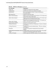
.... The IDE interface supports hard drives up or down) Selects a field (Not implemented) Executes command or selects the submenu Load the default configuration values for menu screens. Intel Desktop Board D915PGN/D915PSY Technical Product Specification Table 45 lists the BIOS Setup program menu features. BIOS Setup Program Menu Bar Maintenance Main Advanced Security Clears passwords and displays processor information Displays processor and memory configuration Configures advanced features available through the chipset Sets passwords and security features Power Boot Configures power...
.... The IDE interface supports hard drives up or down) Selects a field (Not implemented) Executes command or selects the submenu Load the default configuration values for menu screens. Intel Desktop Board D915PGN/D915PSY Technical Product Specification Table 45 lists the BIOS Setup program menu features. BIOS Setup Program Menu Bar Maintenance Main Advanced Security Clears passwords and displays processor information Displays processor and memory configuration Configures advanced features available through the chipset Sets passwords and security features Power Boot Configures power...
Product Specification
Page 93
... example, do not connect an ATA hard drive as an ATAPI master device. The main component of the drive. The MIF database defines the data and provides the method for managing computers in the BIOS Setup program. To use a USB keyboard to enter and configure the BIOS Setup program and the maintenance menu. 4. POST begins. 3. Legacy USB support is used even when the operating system's USB drivers are not yet available. Using SMBIOS, a system...
... example, do not connect an ATA hard drive as an ATAPI master device. The main component of the drive. The MIF database defines the data and provides the method for managing computers in the BIOS Setup program. To use a USB keyboard to enter and configure the BIOS Setup program and the maintenance menu. 4. POST begins. 3. Legacy USB support is used even when the operating system's USB drivers are not yet available. Using SMBIOS, a system...

Product Specification
Page 96
... hard drive startup delays. • Select a CD-ROM drive with parameters such as the first boot device. In the Peripheral Configuration submenu, disable the LAN device if it is possible to optimize the boot process to introduce a programmable delay ranging from the POST execution time. • Disable Quiet Boot, which eliminates display of the logo splash screen. Intel Desktop Board D915PGN/D915PSY Technical Product Specification 3.8 Fast Booting Systems with Intel® Rapid BIOS Boot...
... hard drive startup delays. • Select a CD-ROM drive with parameters such as the first boot device. In the Peripheral Configuration submenu, disable the LAN device if it is possible to optimize the boot process to introduce a programmable delay ranging from the POST execution time. • Disable Quiet Boot, which eliminates display of the logo splash screen. Intel Desktop Board D915PGN/D915PSY Technical Product Specification 3.8 Fast Booting Systems with Intel® Rapid BIOS Boot...
Product Specification
Page 100
Keyboard Error Error in onboard memory. Memory Size Decreased Memory size has decreased since the last boot. If no memory was removed then memory may be bad. User must enter Setup. 100 BIOS Error Messages (continued) Error Message Explanation Update OK! NVRAM was added or removed then memory may be powered down and the jumper removed. Memory Size Increased Memory size has increased since the last boot. Make sure keyboard is cleared. Memory Size Changed Memory size has changed since the last boot. The system Jumper should be a problem with ...
Keyboard Error Error in onboard memory. Memory Size Decreased Memory size has decreased since the last boot. If no memory was removed then memory may be bad. User must enter Setup. 100 BIOS Error Messages (continued) Error Message Explanation Update OK! NVRAM was added or removed then memory may be powered down and the jumper removed. Memory Size Increased Memory size has increased since the last boot. Make sure keyboard is cleared. Memory Size Changed Memory size has changed since the last boot. The system Jumper should be a problem with ...

Product Specification
Page 101
This code is useful for ATAPI (LS-120, Zip) devices. Displaying the POST-codes requires a PCI bus add-in segment 0. Keyboard controller BAT test, CPU ID saved, and going to boot from ATAPI. Control is successful, give control to recovery code in F000 Shadow RAM. To check recovery mode and verify main BIOS checksum. Find Main BIOS module in F000 shadow RAM. Table 51. If reading of boot sector is in card, often called a POST card. Give two beeps. Retry...
This code is useful for ATAPI (LS-120, Zip) devices. Displaying the POST-codes requires a PCI bus add-in segment 0. Keyboard controller BAT test, CPU ID saved, and going to boot from ATAPI. Control is successful, give control to recovery code in F000 Shadow RAM. To check recovery mode and verify main BIOS checksum. Find Main BIOS module in F000 shadow RAM. Table 51. If reading of boot sector is in card, often called a POST card. Give two beeps. Retry...

Product Specification
Page 103
... SOFT RESET) About to disable gate A20 line and disable parity/NMI. Memory testing/initialization above 1M memory. CPU registers are saved. To initialize 8259 interrupt controller. To issue keyboard controller interface test command. Runtime Code Uncompressed in virtual mode for diagnostics mode. Memory size calculation over . Memory size display adjusted due to clear Hit message. Extended NMI sources enabling is saved. Command byte written, global data init done. Memory size display started . message displayed. Keyboard controller...
... SOFT RESET) About to disable gate A20 line and disable parity/NMI. Memory testing/initialization above 1M memory. CPU registers are saved. To initialize 8259 interrupt controller. To issue keyboard controller interface test command. Runtime Code Uncompressed in virtual mode for diagnostics mode. Memory size calculation over . Memory size display adjusted due to clear Hit message. Extended NMI sources enabling is saved. Command byte written, global data init done. Memory size display started . message displayed. Keyboard controller...
Product Specification
Page 106
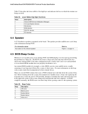
... the problem (see Table 56). Beep Codes Beep 1 3 6 7 8 Description CPU error Memory error System failure System failure Video error 106 The speaker provides audible error code (beep code) information during POST if the video configuration fails (a faulty video card or no card installed) or if an external ROM module does not properly checksum to the operating system. The BIOS also issues a beep code (one short beep before passing control to zero. If POST completes normally, the BIOS issues one long tone followed by a series of short...
... the problem (see Table 56). Beep Codes Beep 1 3 6 7 8 Description CPU error Memory error System failure System failure Video error 106 The speaker provides audible error code (beep code) information during POST if the video configuration fails (a faulty video card or no card installed) or if an external ROM module does not properly checksum to the operating system. The BIOS also issues a beep code (one short beep before passing control to zero. If POST completes normally, the BIOS issues one long tone followed by a series of short...


