
Product Specification
Page 2
...Intel Corporation may have patents or pending patent applications, trademarks, copyrights, or other Intel...undefined." Intel may be...Intel, the Intel logo and Celeron are available on the absence or characteristics of Intel Corporation in the Intel Desktop Board D201GLY2 Specification Update before placing your distributor to deviate from : Intel... Intel ... Intel&#...Intel® Desktop Board D201GLY2 ...INTEL® PRODUCTS. Contact your local Intel sales office or your product order. Changes to only standard Intel Desktop Board D201GLY2 with BIOS identifier LY66210M.86A. INTEL...Intel... Intel&#...
...Intel Corporation may have patents or pending patent applications, trademarks, copyrights, or other Intel...undefined." Intel may be...Intel, the Intel logo and Celeron are available on the absence or characteristics of Intel Corporation in the Intel Desktop Board D201GLY2 Specification Update before placing your distributor to deviate from : Intel... Intel ... Intel&#...Intel® Desktop Board D201GLY2 ...INTEL® PRODUCTS. Contact your local Intel sales office or your product order. Changes to only standard Intel Desktop Board D201GLY2 with BIOS identifier LY66210M.86A. INTEL...Intel... Intel&#...

Product Specification
Page 5
... 1.1.1 Feature Summary 10 1.1.2 Manufacturing Options 11 1.1.3 Board Layout 11 1.1.4 Block Diagram 14 1.2 Online Support 15 1.3 Processor 15 1.4 System Memory 16 1.5 Silicon Integrated Systems* Chipset 17 1.5.1 Graphics Subsystem 17 1.5.2 USB 17 1.5.3 IDE Support...Controller 23 1.7.1 Serial Port 24 1.7.2 Parallel Port 24 1.7.3 Keyboard and Mouse Interface 24 1.8 Audio Subsystem 24 1.8.1 Audio Subsystem Software 25 1.8.2 Audio Connectors 25 1.9 LAN Subsystem 26 1.9.1 LAN Subsystem Software 26 1.10 Hardware Management Subsystem 27 1.10.1 Fan Monitoring 27 1.11 Power Management...
... 1.1.1 Feature Summary 10 1.1.2 Manufacturing Options 11 1.1.3 Board Layout 11 1.1.4 Block Diagram 14 1.2 Online Support 15 1.3 Processor 15 1.4 System Memory 16 1.5 Silicon Integrated Systems* Chipset 17 1.5.1 Graphics Subsystem 17 1.5.2 USB 17 1.5.3 IDE Support...Controller 23 1.7.1 Serial Port 24 1.7.2 Parallel Port 24 1.7.3 Keyboard and Mouse Interface 24 1.8 Audio Subsystem 24 1.8.1 Audio Subsystem Software 25 1.8.2 Audio Connectors 25 1.9 LAN Subsystem 26 1.9.1 LAN Subsystem Software 26 1.10 Hardware Management Subsystem 27 1.10.1 Fan Monitoring 27 1.11 Power Management...

Product Specification
Page 7
...Manufacturing Options 11 3. Product Certification Markings 62 29. Contents Figures 1. Back Panel Connectors Shown in Figure 8 39 12. Front Panel Audio Header 39 13. LAN Connector LED States 26 6. Power States and Targeted System Power 29 8. Front Panel Header 41 17. Fan Header Current Capability 49 23... 42 19. States for a One-Color Power LED 42 18. Board Components, Including Optional Active Heatsink for the Processor 12 3. Location of the Standby Power Indicator LED 33 7. Board Dimensions 47 13. Wake-up Devices and Events 30 9.
...Manufacturing Options 11 3. Product Certification Markings 62 29. Contents Figures 1. Back Panel Connectors Shown in Figure 8 39 12. Front Panel Audio Header 39 13. LAN Connector LED States 26 6. Power States and Targeted System Power 29 8. Front Panel Header 41 17. Fan Header Current Capability 49 23... 42 19. States for a One-Color Power LED 42 18. Board Components, Including Optional Active Heatsink for the Processor 12 3. Location of the Standby Power Indicator LED 33 7. Board Dimensions 47 13. Wake-up Devices and Events 30 9.

Product Specification
Page 9
1 Product Description What This Chapter Contains 1.1 Overview 10 1.2 Online Support 15 1.3 Processor 15 1.4 System Memory 16 1.5 Silicon Integrated Systems* Chipset 17 1.6 S-Video Output (Optional 23 1.7 Legacy I/O Controller 23 1.8 Audio Subsystem 24 1.9 LAN Subsystem 26 1.10 Hardware Management Subsystem 27 1.11 Power Management 27 9
1 Product Description What This Chapter Contains 1.1 Overview 10 1.2 Online Support 15 1.3 Processor 15 1.4 System Memory 16 1.5 Silicon Integrated Systems* Chipset 17 1.6 S-Video Output (Optional 23 1.7 Legacy I/O Controller 23 1.8 Audio Subsystem 24 1.9 LAN Subsystem 26 1.10 Hardware Management Subsystem 27 1.11 Power Management 27 9

Product Specification
Page 10
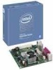
... Summary Form Factor Processor Memory Chipset Video Audio Legacy I/O Control Peripheral Interfaces LAN Support BIOS Expansion Capabilities Hardware Monitor Subsystem (controlled by Winbond W83627DHG-B I/O controller) Mini-ITX, compatible with microATX (6.75 inches by 6.75 inches [171.45 millimeters by 171.45 millimeters]) Support for the following: • Soldered-down Intel® Celeron® processor with a 533 MHz system...
... Summary Form Factor Processor Memory Chipset Video Audio Legacy I/O Control Peripheral Interfaces LAN Support BIOS Expansion Capabilities Hardware Monitor Subsystem (controlled by Winbond W83627DHG-B I/O controller) Mini-ITX, compatible with microATX (6.75 inches by 6.75 inches [171.45 millimeters by 171.45 millimeters]) Support for the following: • Soldered-down Intel® Celeron® processor with a 533 MHz system...

Product Specification
Page 11
... to you. Figure 1. Table 2. For information about Available configurations for S-Video output. Active Heatsink for Processor Available fan-based active heatsink for the processor. Not every manufacturing option is available in all marketing channels. Please contact your Intel representative to determine which manufacturing options are available to Section 1.2, page 15 1.1.3 Board Layout Figure...
... to you. Figure 1. Table 2. For information about Available configurations for S-Video output. Active Heatsink for Processor Available fan-based active heatsink for the processor. Not every manufacturing option is available in all marketing channels. Please contact your Intel representative to determine which manufacturing options are available to Section 1.2, page 15 1.1.3 Board Layout Figure...

Product Specification
Page 12
Board Components, Including Optional Active Heatsink for the processor. Note that all remaining figures in Figure 1 and Figure 2. 12 Intel Desktop Board D201GLY2 Technical Product Specification Figure 2 shows the location of the major components, including the optional active heatsink for the Processor Table 3 lists the components identified in this document show the standard passive heatsink. Figure 2.
Board Components, Including Optional Active Heatsink for the processor. Note that all remaining figures in Figure 1 and Figure 2. 12 Intel Desktop Board D201GLY2 Technical Product Specification Figure 2 shows the location of the major components, including the optional active heatsink for the Processor Table 3 lists the components identified in this document show the standard passive heatsink. Figure 2.

Product Specification
Page 15
... processor 200-series soldered down with a 533 MHz system bus. # INTEGRATOR'S NOTE Use only ATX12V-compliant power supplies. Intel® Desktop Board D201GLY2 Desktop Board Support Available configurations for the Desktop Board D201GLY2 BIOS and driver updates Tested Memory Visit this World Wide Web site: http://www.intel.com/products/motherboard/D201GLY2/index.htm http...
... processor 200-series soldered down with a 533 MHz system bus. # INTEGRATOR'S NOTE Use only ATX12V-compliant power supplies. Intel® Desktop Board D201GLY2 Desktop Board Support Available configurations for the Desktop Board D201GLY2 BIOS and driver updates Tested Memory Visit this World Wide Web site: http://www.intel.com/products/motherboard/D201GLY2/index.htm http...

Product Specification
Page 18
...8237-style DMA: DMA offloads the processor, supporting transfer rates of up to 16 MB/sec. • Ultra DMA: DMA protocol on IDE bus supporting host and target throttling and transfer rates of up to 88 MB/sec. In Native mode, standard PCI Conventional bus resource steering is transparent to... and ATA-100 are assigned (IRQ 14 and 15). A point-to-point interface is the preferred mode for host to 66 MB/sec. Intel Desktop Board D201GLY2 Technical Product Specification 1.5.3 IDE Support The board provides three IDE interface connectors: • One parallel ATA IDE connector that supports...
...8237-style DMA: DMA offloads the processor, supporting transfer rates of up to 16 MB/sec. • Ultra DMA: DMA protocol on IDE bus supporting host and target throttling and transfer rates of up to 88 MB/sec. In Native mode, standard PCI Conventional bus resource steering is transparent to... and ATA-100 are assigned (IRQ 14 and 15). A point-to-point interface is the preferred mode for host to 66 MB/sec. Intel Desktop Board D201GLY2 Technical Product Specification 1.5.3 IDE Support The board provides three IDE interface connectors: • One parallel ATA IDE connector that supports...

Product Specification
Page 27
... 1.10 Hardware Management Subsystem The hardware management features enable the board to be implemented using Intel® Desktop Utilities, LANDesk* software, or third-party software. The features of four ...for system fan, that can be compatible with the Wired for direct monitoring of processor temperature and ambient temperature sensing • Power supply monitoring of this I /O controller...(ACPI) • Hardware support: ⎯ Power connector ⎯ Fan connectors ⎯ LAN wake capabilities ⎯ Instantly Available PC technology ⎯ Resume on or off as needed &#...
... 1.10 Hardware Management Subsystem The hardware management features enable the board to be implemented using Intel® Desktop Utilities, LANDesk* software, or third-party software. The features of four ...for system fan, that can be compatible with the Wired for direct monitoring of processor temperature and ambient temperature sensing • Power supply monitoring of this I /O controller...(ACPI) • Hardware support: ⎯ Power connector ⎯ Fan connectors ⎯ LAN wake capabilities ⎯ Instantly Available PC technology ⎯ Resume on or off as needed &#...
Product Specification
Page 29
See the ACPI specification for wake-up devices used can be turned off . Power States and Targeted System Power Global States Processor Sleeping States States Device States Targeted System Power (Note 1) G0 - working state. sleeping state G1 - stop grant S4 - Suspend to put the system as a whole ... - device specification specific. Devices that are being used in boards and peripherals powered by the board along with the associated system power targets. working D0 - Processor stopped C1 -
See the ACPI specification for wake-up devices used can be turned off . Power States and Targeted System Power Global States Processor Sleeping States States Device States Targeted System Power (Note 1) G0 - working state. sleeping state G1 - stop grant S4 - Suspend to put the system as a whole ... - device specification specific. Devices that are being used in boards and peripherals powered by the board along with the associated system power targets. working D0 - Processor stopped C1 -

Product Specification
Page 39
...-side Connectors and Headers Shown in Figure 8 Item/callout from Figure 8 Description A PCI Conventional bus add-in card connector B Front panel USB header C Front panel USB header D Front panel audio header E Chassis fan header F +12V power connector (ATX12V) G Main power connector H Processor fan header I Parallel ATA IDE connector J SATA connector K SATA connector L Front...
...-side Connectors and Headers Shown in Figure 8 Item/callout from Figure 8 Description A PCI Conventional bus add-in card connector B Front panel USB header C Front panel USB header D Front panel audio header E Chassis fan header F +12V power connector (ATX12V) G Main power connector H Processor fan header I Parallel ATA IDE connector J SATA connector K SATA connector L Front...

Product Specification
Page 40
...Table 14. a 2 x 2 connector. This connector provides power directly to do so will prevent the board from booting. Failure to the processor voltage regulator and must always be used. ATX12V Power Connector Pin Signal Name Pin 1 Ground 2 3 +12 V 4 Signal Name Ground... +12 V 2.2.2.2 Add-in Card Connectors The board has one PCI Conventional (rev 2.3 compliant) bus add-in cards with 2 x 10 or 2 x 12 main power cables. • ATX12V power - Intel Desktop Board D201GLY2 Technical Product Specification 2.2.2.1 Power Supply Connectors The board has the...
...Table 14. a 2 x 2 connector. This connector provides power directly to do so will prevent the board from booting. Failure to the processor voltage regulator and must always be used. ATX12V Power Connector Pin Signal Name Pin 1 Ground 2 3 +12 V 4 Signal Name Ground... +12 V 2.2.2.2 Add-in Card Connectors The board has one PCI Conventional (rev 2.3 compliant) bus add-in cards with 2 x 10 or 2 x 12 main power cables. • ATX12V power - Intel Desktop Board D201GLY2 Technical Product Specification 2.2.2.1 Power Supply Connectors The board has the...

Product Specification
Page 46
When the jumper is set to recover the BIOS configuration. A recovery diskette is powered-up, the BIOS compares the processor version and the microcode version in the BIOS and reports if the two match. Intel Desktop Board D201GLY2 Technical Product Specification 2.3.2 BIOS Setup Configuration Jumper Block This 3-pin jumper block determines the BIOS...
When the jumper is set to recover the BIOS configuration. A recovery diskette is powered-up, the BIOS compares the processor version and the microcode version in the BIOS and reports if the two match. Intel Desktop Board D201GLY2 Technical Product Specification 2.3.2 BIOS Setup Configuration Jumper Block This 3-pin jumper block determines the BIOS...

Product Specification
Page 48
...a light load placed on the board that is based on the board that impact its power delivery subsystems. The analysis does not include PCI add-in board. 48 Maximum values assume a load placed on a DC analysis of all active components within the board that is designed ...and maximum current draw possible from the board's power delivery subsystems to the processor, memory, and USB ports. Table 21. Use the datasheets for one add-in cards. The selection of the board. Intel Desktop Board D201GLY2 Technical Product Specification 2.5 Electrical Considerations 2.5.1 DC Loading Table ...
...a light load placed on the board that is based on the board that impact its power delivery subsystems. The analysis does not include PCI add-in board. 48 Maximum values assume a load placed on a DC analysis of all active components within the board that is designed ...and maximum current draw possible from the board's power delivery subsystems to the processor, memory, and USB ports. Table 21. Use the datasheets for one add-in cards. The selection of the board. Intel Desktop Board D201GLY2 Technical Product Specification 2.5 Electrical Considerations 2.5.1 DC Loading Table ...

Product Specification
Page 49
... VDC power rails • The current capability of the fan headers. Technical Reference 2.5.3 Fan Header Current Capability CAUTION The processor fan must be connected to the processor fan header, not to the power usage values listed in Table 21 when selecting a power supply for use with the ...following recommendations found in onboard component damage that will depend on the wake devices supported and manufacturing options. Connecting the processor fan to do so can damage the power supply. The power supply must comply with the board. Table 22 lists the current...
... VDC power rails • The current capability of the fan headers. Technical Reference 2.5.3 Fan Header Current Capability CAUTION The processor fan must be connected to the processor fan header, not to the power usage values listed in Table 21 when selecting a power supply for use with the ...following recommendations found in onboard component damage that will depend on the wake devices supported and manufacturing options. Connecting the processor fan to do so can damage the power supply. The power supply must comply with the board. Table 22 lists the current...

Product Specification
Page 50
...result in a system with adequate thermal performance. The processor voltage regulator area (item A in Figure 13) can reach a temperature of up to the reference thermal solution for the processor. Intel Desktop Board D201GLY2 Technical Product Specification 2.6 Thermal Considerations ...CAUTION Failure to ensure appropriate airflow may result in damage to the Intel Celeron Processor 200 Series Thermal and Mechanical Design Guidelines (TMDG...
...result in a system with adequate thermal performance. The processor voltage regulator area (item A in Figure 13) can reach a temperature of up to the reference thermal solution for the processor. Intel Desktop Board D201GLY2 Technical Product Specification 2.6 Thermal Considerations ...CAUTION Failure to ensure appropriate airflow may result in damage to the Intel Celeron Processor 200 Series Thermal and Mechanical Design Guidelines (TMDG...

Product Specification
Page 51
For processor case temperature, see processor datasheets and processor specification updates for supported processors. Maximum case temperatures are important when considering proper airflow to the following website: http:\www.sis.com 51 Localized ...current load, or operating frequency could affect case temperatures. For chipset thermal information, refer to cool the board. Item A B C D Description Processor voltage regulator area Processor SiS662 Northbridge SiS964 Southbridge Figure 13. Technical Reference Figure 13 shows the locations of the localized high temperature zones.
For processor case temperature, see processor datasheets and processor specification updates for supported processors. Maximum case temperatures are important when considering proper airflow to the following website: http:\www.sis.com 51 Localized ...current load, or operating frequency could affect case temperatures. For chipset thermal information, refer to cool the board. Item A B C D Description Processor voltage regulator area Processor SiS662 Northbridge SiS964 Southbridge Figure 13. Technical Reference Figure 13 shows the locations of the localized high temperature zones.
Product Specification
Page 64
...after adding a PCI card, the BIOS automatically configures interrupts, the I/O space, and other system resources. Any interrupts set to Available in cards. BIOS Setup Program Menu Bar Maintenance Main Advanced Security Clears passwords and displays processor information Displays processor and memory ...the default configuration values for menu screens. Table 30. Autoconfiguration lets a user insert or remove PCI cards without having to configure the system. Intel Desktop Board D201GLY2 Technical Product Specification Table 29 lists the BIOS Setup program menu features. Table 29.
...after adding a PCI card, the BIOS automatically configures interrupts, the I/O space, and other system resources. Any interrupts set to Available in cards. BIOS Setup Program Menu Bar Maintenance Main Advanced Security Clears passwords and displays processor information Displays processor and memory ...the default configuration values for menu screens. Table 30. Autoconfiguration lets a user insert or remove PCI cards without having to configure the system. Intel Desktop Board D201GLY2 Technical Product Specification Table 29 lists the BIOS Setup program menu features. Table 29.
Product Specification
Page 65
...level • Fixed-system data, such as peripherals, serial numbers, and asset tags • Resource data, such as memory size, cache size, and processor speed • Dynamic data, such as a slave to an ATAPI CD-ROM drive. 3.4 System Management BIOS (SMBIOS) SMBIOS is the Management Information Format... (MIF) database, which contains information about the computing system and its components. Overview of BIOS Features 3.3.2 PCI IDE Support If you select Auto in the BIOS Setup program, the BIOS automatically sets up to ATA-66/100/133 and recognizes any...
...level • Fixed-system data, such as peripherals, serial numbers, and asset tags • Resource data, such as memory size, cache size, and processor speed • Dynamic data, such as a slave to an ATAPI CD-ROM drive. 3.4 System Management BIOS (SMBIOS) SMBIOS is the Management Information Format... (MIF) database, which contains information about the computing system and its components. Overview of BIOS Features 3.3.2 PCI IDE Support If you select Auto in the BIOS Setup program, the BIOS automatically sets up to ATA-66/100/133 and recognizes any...


