Instruction Manual
Page 3
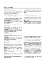
... US patents: #4,590,473, #4,636,791, #5,148,482, #5,185,796, #5,271,017, #5,377,229. cohol when cleaning the IC-R9500, as benzine or al- AVOID placing the receiver against continuous high volume operation. The LCD display may reduce receiver performance and/or damage to...your authority to operate this technology is protected by unauthorized internal adjustment. If you will not use by Icom Inc., could void your ears, reduce the volume or discontinue use chemical agents such as they can damage the receiver's surfaces. This voice coding Technology is installed...
... US patents: #4,590,473, #4,636,791, #5,148,482, #5,185,796, #5,271,017, #5,377,229. cohol when cleaning the IC-R9500, as benzine or al- AVOID placing the receiver against continuous high volume operation. The LCD display may reduce receiver performance and/or damage to...your authority to operate this technology is protected by unauthorized internal adjustment. If you will not use by Icom Inc., could void your ears, reduce the volume or discontinue use chemical agents such as they can damage the receiver's surfaces. This voice coding Technology is installed...

Instruction Manual
Page 4
... cables to [DATA IN], [LAN] or [USB]. !2 (see p. 2-7 for screw hole 2 !2 Ferrite bead 3 *May differ from that shown according to version. †These screw are used when removing rack mounting han- SUPPLIED ACCESSORIES q w e r (FH M4×16 mm) t y u i o !0 (FH M4×12 mm) !1 (PH M4×8 mm) FH: Flat head PH...
... cables to [DATA IN], [LAN] or [USB]. !2 (see p. 2-7 for screw hole 2 !2 Ferrite bead 3 *May differ from that shown according to version. †These screw are used when removing rack mounting han- SUPPLIED ACCESSORIES q w e r (FH M4×16 mm) t y u i o !0 (FH M4×12 mm) !1 (PH M4×8 mm) FH: Flat head PH...
Instruction Manual
Page 7
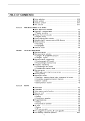
...back 6-5 ■ Voice set mode 6-6 MEMORY OPERATION ■ Memory channels 7-2 ■ Memory channel selection 7-3 D Using the [M-CH]/[BANK] selectors 7-3 D Using the keypad 7-3 ■ Memory channel programming 7-4 D Programming in VFO mode 7-4 D Programming in memory mode 7-4 &#...Memory names 7-6 D Editing (programming) memory names 7-6 ■ Memory clearing 7-6 ■ Memory list screen 7-7 D Selecting a memory channel using the memory list screen ...... 7-7 D Confirming programmed memory channels 7-7 D Memory bank set 7-8 D Editing memory channel 7-9 SCANS ■ ...
...back 6-5 ■ Voice set mode 6-6 MEMORY OPERATION ■ Memory channels 7-2 ■ Memory channel selection 7-3 D Using the [M-CH]/[BANK] selectors 7-3 D Using the keypad 7-3 ■ Memory channel programming 7-4 D Programming in VFO mode 7-4 D Programming in memory mode 7-4 &#...Memory names 7-6 D Editing (programming) memory names 7-6 ■ Memory clearing 7-6 ■ Memory list screen 7-7 D Selecting a memory channel using the memory list screen ...... 7-7 D Confirming programmed memory channels 7-7 D Memory bank set 7-8 D Editing memory channel 7-9 SCANS ■ ...
Instruction Manual
Page 12
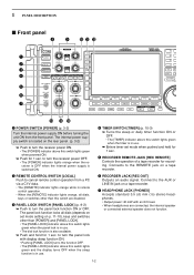
...] and [PANEL LOCK]. • The [PANEL LOCK] indicator above this switch lights green and the display turns OFF when the sleep function is in use . • The dial lock function is located on the rear panel. (p. 3-2) ➥ Push to turn the receiver power ON. • The.... Connects to turn the receiver power OFF. • The [POWER] indicator lights orange when the receiver is OFF when the internal power supply is in use . u HEADPHONE JACK [PHONES] Accepts standard 3.5 (d) mm (1⁄8) stereo headphones. • Output power: 40 mW with display sleep function ON. •...
...] and [PANEL LOCK]. • The [PANEL LOCK] indicator above this switch lights green and the display turns OFF when the sleep function is in use . • The dial lock function is located on the rear panel. (p. 3-2) ➥ Push to turn the receiver power ON. • The.... Connects to turn the receiver power OFF. • The [POWER] indicator lights orange when the receiver is OFF when the internal power supply is in use . u HEADPHONE JACK [PHONES] Accepts standard 3.5 (d) mm (1⁄8) stereo headphones. • Output power: 40 mW with display sleep function ON. •...
Instruction Manual
Page 13
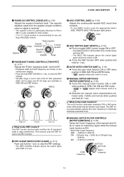
... CONTROLS [TWIN PBT] (p. 5-11) Adjusts the IF filter "passband width" via the DSP. • Passband width and shift frequency are available in use . !5 MANUAL NOTCH FILTER CONTROLS [NOTCH1]/[NOTCH2] (p. 5-16) Varies the "notch" frequency of the manual notch filter to clear the PBT settings. ...and FSK modes. (PBT1) (PBT2) - + !1 AGC CONTROL [AGC] (p. 5-10) Adjusts the continuously-variable AGC circuit time constant. • To use [AGC] control, push the appropriate band's [AGC VR/OFF] ([AGC VR] indicator lights green). The squelch disables output from the speaker (closed condition) ...
... CONTROLS [TWIN PBT] (p. 5-11) Adjusts the IF filter "passband width" via the DSP. • Passband width and shift frequency are available in use . !5 MANUAL NOTCH FILTER CONTROLS [NOTCH1]/[NOTCH2] (p. 5-16) Varies the "notch" frequency of the manual notch filter to clear the PBT settings. ...and FSK modes. (PBT1) (PBT2) - + !1 AGC CONTROL [AGC] (p. 5-10) Adjusts the continuously-variable AGC circuit time constant. • To use [AGC] control, push the appropriate band's [AGC VR/OFF] ([AGC VR] indicator lights green). The squelch disables output from the speaker (closed condition) ...

Instruction Manual
Page 14
... filter ON or OFF during FSK mode operation. (p. 4-11) • " APF " appears when audio peak filter is in use. • " TPF " appears when twin peak filter is in use. The noise blanker reduces pulse-type noise such as that generated by automobile ignition systems. This function cannot be...-pulse-type noise. • The [NB] indicator above this switch lights green when the function is in use. ➥ During CW mode operation, push and hold for maximum readability. • To use this control, noise reduction must be ON. This comes from noise blanker 1, 2, or OFF when pushed....
... filter ON or OFF during FSK mode operation. (p. 4-11) • " APF " appears when audio peak filter is in use. • " TPF " appears when twin peak filter is in use. The noise blanker reduces pulse-type noise such as that generated by automobile ignition systems. This function cannot be...-pulse-type noise. • The [NB] indicator above this switch lights green when the function is in use. ➥ During CW mode operation, push and hold for maximum readability. • To use this control, noise reduction must be ON. This comes from noise blanker 1, 2, or OFF when pushed....
Instruction Manual
Page 15
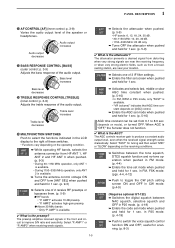
... depends on the receiving conditions. ➥ Switches between NAC squelch, selective squelch and OFF in P25 mode. (p. 4-19) ➥ Push to improve S/N ratio and sensitivity. useful for 1 sec. (p. 5-9) ✔ What is the attenuator? Select "P. Audio output increases Audio output decreases @3 BASS RESPONSE CONTROL [BASS] (outer control; Bass level increases ➥ Selects...
... depends on the receiving conditions. ➥ Switches between NAC squelch, selective squelch and OFF in P25 mode. (p. 4-19) ➥ Push to improve S/N ratio and sensitivity. useful for 1 sec. (p. 5-9) ✔ What is the attenuator? Select "P. Audio output increases Audio output decreases @3 BASS RESPONSE CONTROL [BASS] (outer control; Bass level increases ➥ Selects...
Instruction Manual
Page 17
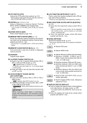
... Stores the selected readout frequency and operating mode into the displayed memory channel when pushed and held for 1 sec. • This function is in use . ➥ Turns the automatic tuning function ON or OFF in SSB mode. ➥ Switches between LSB and USB mode when pushed and held for... [AFC•AUTOTUNE] ➥ Turns the AFC function ON or OFF in FM or WFM modes. • " AFC " appears when AFC function is in use . • 1⁄4 function sets dial rotation to 1⁄4 of displayed memory channel. #8 SPEAKER Outputs audio signals. #9 1/4-SPEED TUNING SWITCH [1/4] ➥ ...
... Stores the selected readout frequency and operating mode into the displayed memory channel when pushed and held for 1 sec. • This function is in use . ➥ Turns the automatic tuning function ON or OFF in SSB mode. ➥ Switches between LSB and USB mode when pushed and held for... [AFC•AUTOTUNE] ➥ Turns the AFC function ON or OFF in FM or WFM modes. • " AFC " appears when AFC function is in use . • 1⁄4 function sets dial rotation to 1⁄4 of displayed memory channel. #8 SPEAKER Outputs audio signals. #9 1/4-SPEED TUNING SWITCH [1/4] ➥ ...
Instruction Manual
Page 21
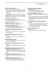
... remote control of the receiver. ➥ Used for transceive operation with a PL259 plug connector. @0 HF ANTENNA CONNECTOR 2 [HF ANT 2] (p. 2-5) Accepts a 500 Ω antenna for external control of the IC-R9500 without the optional CT-17, or the ...FSK decoded signal output. Covers the 1150-3335 MHz frequency range. @6 EXTERNAL DISPLAY TERMINAL [EXT-DISPLAY] (p. 2-10) Connects to prevent electrical shocks, TVI, BCI and other problems. !9 HF ANTENNA CONNECTOR 1 [HF ANT 1] (p. 2-5) Accepts a 50 Ω antenna for HF bands with another Icom...
... remote control of the receiver. ➥ Used for transceive operation with a PL259 plug connector. @0 HF ANTENNA CONNECTOR 2 [HF ANT 2] (p. 2-5) Accepts a 500 Ω antenna for external control of the IC-R9500 without the optional CT-17, or the ...FSK decoded signal output. Covers the 1150-3335 MHz frequency range. @6 EXTERNAL DISPLAY TERMINAL [EXT-DISPLAY] (p. 2-10) Connects to prevent electrical shocks, TVI, BCI and other problems. !9 HF ANTENNA CONNECTOR 1 [HF ANT 1] (p. 2-5) Accepts a 50 Ω antenna for HF bands with another Icom...

Instruction Manual
Page 23
...mode. (Requires optional UT-122.) (p.4-19) !8 BANK INDICATOR (p. 7-3) Appears when the bank limit function is ON. This function is available in use. 1 PANEL DESCRIPTION o MULTIFUNCTION SWITCH GUIDE Indicates the function of the multifunction switches. !0 LCD FUNCTION SWITCH GUIDE Indicates the function of the LCD ... !1 MULTIFUNCTION SCREEN Shows the screens for IF shift operation. @5 AUDIO PEAK FILTER INDICATOR (p. 4-9) Appears when the audio peak filter function is in use. This function is available in FM, WFM, AM and SSB modes. ➥ " MN1 " or " MN2 " appears when the manual notch...
...mode. (Requires optional UT-122.) (p.4-19) !8 BANK INDICATOR (p. 7-3) Appears when the bank limit function is ON. This function is available in use. 1 PANEL DESCRIPTION o MULTIFUNCTION SWITCH GUIDE Indicates the function of the multifunction switches. !0 LCD FUNCTION SWITCH GUIDE Indicates the function of the LCD ... !1 MULTIFUNCTION SCREEN Shows the screens for IF shift operation. @5 AUDIO PEAK FILTER INDICATOR (p. 4-9) Appears when the audio peak filter function is in use. This function is available in FM, WFM, AM and SSB modes. ➥ " MN1 " or " MN2 " appears when the manual notch...

Instruction Manual
Page 24
Pushing [EXIT/SET] several times returns to the start up screen. See p. 11-3 for set mode arrangement. • Spectrum scope screen (p. 5-2) • Memory channel screen (p. 7-4) • Voice recorder screen (p. 6-3) • Scan screen (p. 5-5) • FSK decoder screen (p. 4-14) • Set mode menu screen (p. 11-2) 1-14 1 PANEL DESCRIPTION ■ Screen menu arrangement The following chart. Choose the desired screen using the following screens can be selected from the start up screen.
Pushing [EXIT/SET] several times returns to the start up screen. See p. 11-3 for set mode arrangement. • Spectrum scope screen (p. 5-2) • Memory channel screen (p. 7-4) • Voice recorder screen (p. 6-3) • Scan screen (p. 5-5) • FSK decoder screen (p. 4-14) • Set mode menu screen (p. 11-2) 1-14 1 PANEL DESCRIPTION ■ Screen menu arrangement The following chart. Choose the desired screen using the following screens can be selected from the start up screen.

Instruction Manual
Page 27
... performance. r Screw the coupling ring onto the connector body. 30 mm ≈ 9⁄8 in 10 mm ≈ 3⁄8 in 1-2 mm ≈ 1⁄16 in 2-3 The IC-R9500 requires at left. w 3 mm 6 mm Strip the cable and fold the braid back over the coaxial cable, then cut the end of the plug body... and tin the braid. Tighten the nut onto the plug body. • Be sure the center pin is poor, your receiver from 100 kHz to use one as long as a well matched 50 Ω antenna and feedline. No space r Plug body Carefully slide the plug body into place aligning the center...
... performance. r Screw the coupling ring onto the connector body. 30 mm ≈ 9⁄8 in 10 mm ≈ 3⁄8 in 1-2 mm ≈ 1⁄16 in 2-3 The IC-R9500 requires at left. w 3 mm 6 mm Strip the cable and fold the braid back over the coaxial cable, then cut the end of the plug body... and tin the braid. Tighten the nut onto the plug body. • Be sure the center pin is poor, your receiver from 100 kHz to use one as long as a well matched 50 Ω antenna and feedline. No space r Plug body Carefully slide the plug body into place aligning the center...

Instruction Manual
Page 28
...;16 mm w FH M4×12 mm CAUTION: NEVER replace the any other than specified screws for attach the side plates. If long screw is used, it is caused to original position, then tighten the supplied 4 screws (FH M4×12). 2 INSTALLATION AND CONNECTIONS ■ TV jumper cable connection (except for... between [VIDEO IN] and [VIDEO OUT]. FH M4×16 mm FH: Flat head ■ Rack mounting handle detachment When removing the rack mounting handles, use the supplied screws for side plate atachment or hiding screw holes.
...;16 mm w FH M4×12 mm CAUTION: NEVER replace the any other than specified screws for attach the side plates. If long screw is used, it is caused to original position, then tighten the supplied 4 screws (FH M4×12). 2 INSTALLATION AND CONNECTIONS ■ TV jumper cable connection (except for... between [VIDEO IN] and [VIDEO OUT]. FH M4×16 mm FH: Flat head ■ Rack mounting handle detachment When removing the rack mounting handles, use the supplied screws for side plate atachment or hiding screw holes.

Instruction Manual
Page 29
... AND CONNECTIONS ■ Required connections D Rear panel [VIDEO IN], [VIDEO OUT] TV jumper cable must be connected when internal TV tuner and LCD are in use (except USA versions). Ground (p. 2-2) Ground connection AC outlet R WARNING...
... AND CONNECTIONS ■ Required connections D Rear panel [VIDEO IN], [VIDEO OUT] TV jumper cable must be connected when internal TV tuner and LCD are in use (except USA versions). Ground (p. 2-2) Ground connection AC outlet R WARNING...

Instruction Manual
Page 30
The optional CT-17 is required when connecting a PC to [REMOTE]. 2-6 DATA socket (pgs.2-12) Antenna 1, 2 Connects a pre-amplifier, converter, etc. [REMOTE], [RS-232C] (p. 13-2) Used for external equipment power supply. (max. 1 A capacity) ACC socket (pgs.2-12) [DC-DC IN] Connects an external power supply (DC 13.5-15 V at least 10 A). ...
The optional CT-17 is required when connecting a PC to [REMOTE]. 2-6 DATA socket (pgs.2-12) Antenna 1, 2 Connects a pre-amplifier, converter, etc. [REMOTE], [RS-232C] (p. 13-2) Used for external equipment power supply. (max. 1 A capacity) ACC socket (pgs.2-12) [DC-DC IN] Connects an external power supply (DC 13.5-15 V at least 10 A). ...

Instruction Manual
Page 32
...350 mVrms 4.7 kΩ When you wish to control a tape recorder via the REMOTE jack. If a tape recorder has a control terminal, this jack can be used for recording control. (2 A/DC max.) The [REC OUT] or [LINE OUT] jack has 350 mV rms/4.7 kΩ output for connection to other audio equipment... connections The [REC REMOTE] jack is grounded when a signal is received and squelch opens. If a tape recorder has a control terminal, this jack can be used for recording control. (2 A/DC max.) The [REC OUT] or [LINE OUT] jack has 350 mV rms/4.7 kΩ output for connection to control a...
...350 mVrms 4.7 kΩ When you wish to control a tape recorder via the REMOTE jack. If a tape recorder has a control terminal, this jack can be used for recording control. (2 A/DC max.) The [REC OUT] or [LINE OUT] jack has 350 mV rms/4.7 kΩ output for connection to other audio equipment... connections The [REC REMOTE] jack is grounded when a signal is received and squelch opens. If a tape recorder has a control terminal, this jack can be used for recording control. (2 A/DC max.) The [REC OUT] or [LINE OUT] jack has 350 mV rms/4.7 kΩ output for connection to control a...

Instruction Manual
Page 33
2 INSTALLATION AND CONNECTIONS D Separately recording audio and frequency When using a stereo tape recorder for recording, received audio and a frequency with a synthesized voice can search ahead of the audio signal recorded in the others set mode (p. ... [AUX IN] jacks L and R • Be sure the "REC SPEECH" item is turned ON, and "SPEECH Mix" item is select OFF in the tape recorder using the frequency recording channel search. [REMOTE] jack [REC REMOTE] [LINE OUT] 350 mVrms 4.7 kΩ [SPEECH OUT] 350 mVrms 4.7 kΩ When you wish to control a tape...
2 INSTALLATION AND CONNECTIONS D Separately recording audio and frequency When using a stereo tape recorder for recording, received audio and a frequency with a synthesized voice can search ahead of the audio signal recorded in the others set mode (p. ... [AUX IN] jacks L and R • Be sure the "REC SPEECH" item is turned ON, and "SPEECH Mix" item is select OFF in the tape recorder using the frequency recording channel search. [REMOTE] jack [REC REMOTE] [LINE OUT] 350 mVrms 4.7 kΩ [SPEECH OUT] 350 mVrms 4.7 kΩ When you wish to control a tape...
Instruction Manual
Page 35
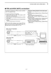
.... r Set the connected terminal unit to the appropriate settings. • Refer to the signal width. (p. 5-12) • Frequency settings depend on the mode used. RS-232C TNC or scan converter Personal computer 2-11 e Set the receiver to the desired frequency as below . w Select FSK mode (or USB, CW modes... for amateur RTTY): [Setting frequency (displayed freq.)] = [Desired freq.] + [Mark freq.] • When using a PC application Rear panel view [ACC] 76 381 54 2 SQLS SQELCH IN GND GND AF AUDIO INPUT • When...
.... r Set the connected terminal unit to the appropriate settings. • Refer to the signal width. (p. 5-12) • Frequency settings depend on the mode used. RS-232C TNC or scan converter Personal computer 2-11 e Set the receiver to the desired frequency as below . w Select FSK mode (or USB, CW modes... for amateur RTTY): [Setting frequency (displayed freq.)] = [Desired freq.] + [Mark freq.] • When using a PC application Rear panel view [ACC] 76 381 54 2 SQLS SQELCH IN GND GND AF AUDIO INPUT • When...

Instruction Manual
Page 36
... Connects to ground. 3 SEND When grounded, attenuator activates GROUND level : -0.5 to ground when squelch opens. Output impedance : 47 kΩ Fixed, regardless of [AF] position in use, the beep tone decreases from the fixed level when the [AF] control is muted. Output current : 100 mA 8 MOUT Output S-meter level. 2 INSTALLATION AND CONNECTIONS...
... Connects to ground. 3 SEND When grounded, attenuator activates GROUND level : -0.5 to ground when squelch opens. Output impedance : 47 kΩ Fixed, regardless of [AF] position in use, the beep tone decreases from the fixed level when the [AF] control is muted. Output current : 100 mA 8 MOUT Output S-meter level. 2 INSTALLATION AND CONNECTIONS...

Instruction Manual
Page 38
...; The receiver power is normal and does not indicate any equipment malfunction. [POWER] ■ Initial settings [AGC]: 12 o'clock [SQL] : Max. Then, reset the receiver using the following procedure. counter clockwise [TREBLE]/[BASS]: 12 o'clock 3-2 w While pushing and holding [CE] and [M-CL], push [POWER] to Section 2. In cooler temperatures, the LCD...
...; The receiver power is normal and does not indicate any equipment malfunction. [POWER] ■ Initial settings [AGC]: 12 o'clock [SQL] : Max. Then, reset the receiver using the following procedure. counter clockwise [TREBLE]/[BASS]: 12 o'clock 3-2 w While pushing and holding [CE] and [M-CL], push [POWER] to Section 2. In cooler temperatures, the LCD...

