Instruction Manual
Page 1
COMMUNICATIONS RECEIVER iR9500 Instruction Manual A-6553H-1EX-q Printed in Japan © 2007 Icom Inc.
COMMUNICATIONS RECEIVER iR9500 Instruction Manual A-6553H-1EX-q Printed in Japan © 2007 Icom Inc.
Instruction Manual
Page 2
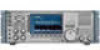
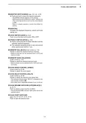
.... portant safety and operating instructions for making the IC-R9500 your IC-R9500. Equipment damage may occur. No risk of choice. TRADEMARKS Icom, Icom Inc. ABOUT RE-EXPORTING THIS PRODUCT: If re...Icom's philosophy of "technology first." If disregarded, inconvenience only. center frequency and fix frequency modes, plus mini-scope displays IMPORTANT READ THIS INSTRUCTION MANUAL CAREFULLY before at- This manual contains im- Please consult with the relevant Government Department in Baudot FSK demodulator ❍ High resolution spectrum scope- We hope you for the IC-R9500...
.... portant safety and operating instructions for making the IC-R9500 your IC-R9500. Equipment damage may occur. No risk of choice. TRADEMARKS Icom, Icom Inc. ABOUT RE-EXPORTING THIS PRODUCT: If re...Icom's philosophy of "technology first." If disregarded, inconvenience only. center frequency and fix frequency modes, plus mini-scope displays IMPORTANT READ THIS INSTRUCTION MANUAL CAREFULLY before at- This manual contains im- Please consult with the relevant Government Department in Baudot FSK demodulator ❍ High resolution spectrum scope- We hope you for the IC-R9500...
Instruction Manual
Page 13
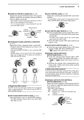
... (PBT1) (PBT2) - + !1 AGC CONTROL [AGC] (p. 5-10) Adjusts the continuously-variable AGC circuit time constant. • To use . ➥ Switches the manual notch characteristics between wide, middle and narrow when pushed and held for 1 sec. ✔ What is also available for other modes. • 11 to reject...for FM or AM. to clear the PBT settings. • The [PBT CLEAR] indicator above this switch lights when PBT is in use. !5 MANUAL NOTCH FILTER CONTROLS [NOTCH1]/[NOTCH2] (p. 5-16) Varies the "notch" frequency of the [SQL] control. High cut Center Low cut ✔ What...
... (PBT1) (PBT2) - + !1 AGC CONTROL [AGC] (p. 5-10) Adjusts the continuously-variable AGC circuit time constant. • To use . ➥ Switches the manual notch characteristics between wide, middle and narrow when pushed and held for 1 sec. ✔ What is also available for other modes. • 11 to reject...for FM or AM. to clear the PBT settings. • The [PBT CLEAR] indicator above this switch lights when PBT is in use. !5 MANUAL NOTCH FILTER CONTROLS [NOTCH1]/[NOTCH2] (p. 5-16) Varies the "notch" frequency of the [SQL] control. High cut Center Low cut ✔ What...
Instruction Manual
Page 19
... announced when pushed and held for 1 sec. %5 MEMORY DIAL [M-CH] (inner control; %1 MONITOR SWITCH [MONI] (pgs. 3-8, 4-4, 4-19) ➥ Push and hold to open the squelch manually. • The [MONI] indicator appears on the display. • While pushing and holding this switch, release any other receiving functions such as the noise blanker...
... announced when pushed and held for 1 sec. %5 MEMORY DIAL [M-CH] (inner control; %1 MONITOR SWITCH [MONI] (pgs. 3-8, 4-4, 4-19) ➥ Push and hold to open the squelch manually. • The [MONI] indicator appears on the display. • While pushing and holding this switch, release any other receiving functions such as the noise blanker...

Instruction Manual
Page 23
... or less) is selected during automatic tuning. This function is available in FM, WFM, AM and SSB modes. ➥ " MN1 " or " MN2 " appears when the manual notch filter function is in use . This function is selected, respectively. 1-13 1 PANEL DESCRIPTION o MULTIFUNCTION SWITCH GUIDE Indicates the function of the multifunction switches. !0 LCD...
... or less) is selected during automatic tuning. This function is available in FM, WFM, AM and SSB modes. ➥ " MN1 " or " MN2 " appears when the manual notch filter function is in use . This function is selected, respectively. 1-13 1 PANEL DESCRIPTION o MULTIFUNCTION SWITCH GUIDE Indicates the function of the multifunction switches. !0 LCD...
Instruction Manual
Page 26
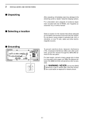
...; Unpacking ■ Selecting a location ■ Grounding After unpacking, immediately report any damage to a long earth-sunk copper rod. iii of accessory equipment included with the IC-R9500, see 'Supplied accessories' on the rear panel. For a description and a diagram of this manual.
...; Unpacking ■ Selecting a location ■ Grounding After unpacking, immediately report any damage to a long earth-sunk copper rod. iii of accessory equipment included with the IC-R9500, see 'Supplied accessories' on the rear panel. For a description and a diagram of this manual.
Instruction Manual
Page 35
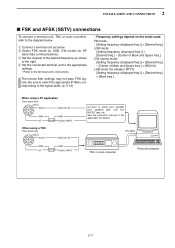
... the terminal unit's instructions. The narrow filter settings may not pass FSK signals. RS-232C TNC or scan converter Personal computer 2-11 See the instruction manual of Mark and Space freq.] + [600 Hz] LSB mode (for details. e Set the receiver to the desired frequency as below . q Connect a terminal unit as shown...
... the terminal unit's instructions. The narrow filter settings may not pass FSK signals. RS-232C TNC or scan converter Personal computer 2-11 See the instruction manual of Mark and Space freq.] + [600 Hz] LSB mode (for details. e Set the receiver to the desired frequency as below . q Connect a terminal unit as shown...

Instruction Manual
Page 50
... ON. You can be heard. • When the received signal's tone (or DTCS code) does not match, tone (DTCS) squelch does not open the squelch manually, push [MONI]. • The squelch opens temporarily while pushing and holding [MONI]. w Push [TONE] several times to the previous indica- 4 RECEIVE MODES ■ Tone /DTCS...
... ON. You can be heard. • When the received signal's tone (or DTCS code) does not match, tone (DTCS) squelch does not open the squelch manually, push [MONI]. • The squelch opens temporarily while pushing and holding [MONI]. w Push [TONE] several times to the previous indica- 4 RECEIVE MODES ■ Tone /DTCS...

Instruction Manual
Page 52
... appear when the attenu- Only 20 dB is received. ator is ON. • Noise blanker (p. 5-15) ➥ Push [NB] switch to turn the manual notch function ON or OFF. • Rotate [NOTCH] control to set the notch frequency. • Notch indicator (above 30 MHz. • "P.AMP1" or...30 MHz. to a comfortable listening level. IMPORTANT! to an undesired signal. 4-6 Only ON/OFF is available above [NOTCH1] or [NOTCH2] switch) lights when either the manual notch is selected, push and hold [AM] for 30-1150 MHz. w Push [AM] to select AM. • " A M " indicator appears. • ...
... appear when the attenu- Only 20 dB is received. ator is ON. • Noise blanker (p. 5-15) ➥ Push [NB] switch to turn the manual notch function ON or OFF. • Rotate [NOTCH] control to set the notch frequency. • Notch indicator (above 30 MHz. • "P.AMP1" or...30 MHz. to a comfortable listening level. IMPORTANT! to an undesired signal. 4-6 Only ON/OFF is available above [NOTCH1] or [NOTCH2] switch) lights when either the manual notch is selected, push and hold [AM] for 30-1150 MHz. w Push [AM] to select AM. • " A M " indicator appears. • ...

Instruction Manual
Page 53
...Noise blanker indicator (above [NB] switch) lights when the noise blanker is ON. • Push [NB] for 30-1150 MHz. ator is ON. • Manual notch filter (p. 5-16) ➥ Push [NOTCH1] or [NOTCH2] switch to set the attenuating fre- ■ Operating SSB [RX] indicator Keypad [AF] [SSB...the S-meter indicates re- r Rotate [AF] to turn the auto tuning func- "P.AMP ON" appears above [NOTCH1] or [NOTCH2] switch) lights when either the manual notch is ON. • AGC (auto gain control) (p. 5-10) ➥ Push [AGC] switch several times to set mode. • Twin PBT (passband tuning...
...Noise blanker indicator (above [NB] switch) lights when the noise blanker is ON. • Push [NB] for 30-1150 MHz. ator is ON. • Manual notch filter (p. 5-16) ➥ Push [NOTCH1] or [NOTCH2] switch to set the attenuating fre- ■ Operating SSB [RX] indicator Keypad [AF] [SSB...the S-meter indicates re- r Rotate [AF] to turn the auto tuning func- "P.AMP ON" appears above [NOTCH1] or [NOTCH2] switch) lights when either the manual notch is ON. • AGC (auto gain control) (p. 5-10) ➥ Push [AGC] switch several times to set mode. • Twin PBT (passband tuning...

Instruction Manual
Page 54
.... • Rotate [NR] control to adjust the noise reduction level. • Noise reduction indicator (above [NOTCH1] or [NOTCH2] switch) lights when either the manual notch is ON. • AGC (auto gain control) (p. 5-10) ➥ Push [AGC] switch several times to set the notch frequency. • Notch... 5-9) ➥ Push [P.AMP] several times to select AGC FAST, AGC MID or AGC SLOW. ➥ Push [AGC VR] to turn the AGC time constant manual setting ON or OFF. • Rotate [AGC] control to adjust the time constant. • 1⁄4 function (p. 3-6) ➥ Push [1/4] to turn the 1&#...
.... • Rotate [NR] control to adjust the noise reduction level. • Noise reduction indicator (above [NOTCH1] or [NOTCH2] switch) lights when either the manual notch is ON. • AGC (auto gain control) (p. 5-10) ➥ Push [AGC] switch several times to set the notch frequency. • Notch... 5-9) ➥ Push [P.AMP] several times to select AGC FAST, AGC MID or AGC SLOW. ➥ Push [AGC VR] to turn the AGC time constant manual setting ON or OFF. • Rotate [AGC] control to adjust the time constant. • 1⁄4 function (p. 3-6) ➥ Push [1/4] to turn the 1&#...

Instruction Manual
Page 56
...you would rather use your FSK terminal or TNC, consult the manual that comes with the mark and shift frequency lines in Baudot decoder. q Edit the desired frequency using the keypad. e Push [F-3•DECODE] to the IC-R9500. 4 RECEIVE MODES ■ Operating FSK [RX] indicator Keypad... [F-3•DECODE] [FSK] Appears Main dial A DSP-based high-quality Baudot FSK decoder is builtin to display the decoder screen. • The IC-R9500 has a built-in the FFT scope. ...
...you would rather use your FSK terminal or TNC, consult the manual that comes with the mark and shift frequency lines in Baudot decoder. q Edit the desired frequency using the keypad. e Push [F-3•DECODE] to the IC-R9500. 4 RECEIVE MODES ■ Operating FSK [RX] indicator Keypad... [F-3•DECODE] [FSK] Appears Main dial A DSP-based high-quality Baudot FSK decoder is builtin to display the decoder screen. • The IC-R9500 has a built-in the FFT scope. ...

Instruction Manual
Page 57
... (p. 5-9) ➥ Push [ATT] several times to select AGC FAST, AGC MID or AGC SLOW. ➥ Push [AGC VR] to turn the AGC time constant manual setting ON or OFF. • Rotate [AGC] control to adjust the time constant. • 1⁄4 function (p. 3-6) ➥ Push [1/4] to turn the noise ...and then rotate [NB] control to adjust the threshold level. • Noise blanker indicator (above [NR] switch) lights when the noise reduction is ON. • Manual notch filter (p. 5-16) ➥ Push [NOTCH1] or [NOTCH2] switch to turn the twin peak filter ON and OFF. • " TPF " appears in ...
... (p. 5-9) ➥ Push [ATT] several times to select AGC FAST, AGC MID or AGC SLOW. ➥ Push [AGC VR] to turn the AGC time constant manual setting ON or OFF. • Rotate [AGC] control to adjust the time constant. • 1⁄4 function (p. 3-6) ➥ Push [1/4] to turn the noise ...and then rotate [NB] control to adjust the threshold level. • Noise blanker indicator (above [NR] switch) lights when the noise reduction is ON. • Manual notch filter (p. 5-16) ➥ Push [NOTCH1] or [NOTCH2] switch to turn the twin peak filter ON and OFF. • " TPF " appears in ...

Instruction Manual
Page 65
.... • Using the receiver's keypad, [0]-[9], can be heard. • When the received signal's code does not match, digital squelch does not open the digital squelch manually, push [MONI]. • The digital squelch opens temporarily while pushing and holding [MONI]. !0 To cancel digital squelch, push [D.SQL] several times to the previous indica...
.... • Using the receiver's keypad, [0]-[9], can be heard. • When the received signal's code does not match, digital squelch does not open the digital squelch manually, push [MONI]. • The digital squelch opens temporarily while pushing and holding [MONI]. !0 To cancel digital squelch, push [D.SQL] several times to the previous indica...
Instruction Manual
Page 82
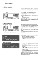
... DSP performs the random noise reduction function. to turn the noise reduction OFF. • [NR] indicator lights off. Set the [NR] control for manual notch via the [NOTCH1]/[NOTCH2] controls. The auto notch can be used in SSB, CW, FSK and AM modes. ➥ Push [ANF] to..." AN " appears when auto notch is in use . ➥ Push [NOTCH1] or [NOTCH2] to attenuate a frequency via the [NOTCH1] or [NOTCH2] controls. The manual notch can result in AM, SSB, CW and FSK modes. • [NOTCH1]/[NOTCH2] indicators above this switch lights green. Setting the [NR] control too high...
... DSP performs the random noise reduction function. to turn the noise reduction OFF. • [NR] indicator lights off. Set the [NR] control for manual notch via the [NOTCH1]/[NOTCH2] controls. The auto notch can be used in SSB, CW, FSK and AM modes. ➥ Push [ANF] to..." AN " appears when auto notch is in use . ➥ Push [NOTCH1] or [NOTCH2] to attenuate a frequency via the [NOTCH1] or [NOTCH2] controls. The manual notch can result in AM, SSB, CW and FSK modes. • [NOTCH1]/[NOTCH2] indicators above this switch lights green. Setting the [NR] control too high...

Instruction Manual
Page 105
... signals for voice components. See p. 8-18 for any scan. • The VSC function resumes the scan on each channel when the scan resume is stopped manually, and does not pause even if it is ON; not applicable when OFF. lated signals, regardless of the voice components changes within 1 sec., scan resumes...
... signals for voice components. See p. 8-18 for any scan. • The VSC function resumes the scan on each channel when the scan resume is stopped manually, and does not pause even if it is ON; not applicable when OFF. lated signals, regardless of the voice components changes within 1 sec., scan resumes...

Instruction Manual
Page 106
... write scan. • [AUTO] Long Push : Auto memory channels are cleared when pushing and holding [AUTO]. (default) • OFF : Auto memory channels must be cleared manually and auto memory write scan stops when 100 channels (A00 to A99) are wrote. Auto SCAN Screen (SCAN Start) Set the automatic scan screen ON...
... write scan. • [AUTO] Long Push : Auto memory channels are cleared when pushing and holding [AUTO]. (default) • OFF : Auto memory channels must be cleared manually and auto memory write scan stops when 100 channels (A00 to A99) are wrote. Auto SCAN Screen (SCAN Start) Set the automatic scan screen ON...

Instruction Manual
Page 112
... screen, if necessary. w Select the desired VFO or memory channel. See scan set before starting auto memory write scan, by pushing and holding [AUTO], or manually. i Push and hold [F-6•RECALL] for 1 sec. The memory clear setting of the auto write bank can be selected from the starting the scan, if...
... screen, if necessary. w Select the desired VFO or memory channel. See scan set before starting auto memory write scan, by pushing and holding [AUTO], or manually. i Push and hold [F-6•RECALL] for 1 sec. The memory clear setting of the auto write bank can be selected from the starting the scan, if...

Instruction Manual
Page 123
... (ANT1) is connected to turn the dial click function ON and OFF manually. • "CLICK" appears. [1/4] ■ Antenna selection HF ANT3 1150-3335MHz 30-1150MHz HF ANT2 HF ANT1 IC-R9500 • Antenna selection [ANT] The IC-R9500 has 3 antenna connectors for bands below 30 MHz which can turn the ...used antenna is also available in the others set mode (p. 11-12). ➥ Push and hold [ANT] for 1 sec. After each operating band the IC-R9500 covers, there is also output from [ANT SEL] connector. • When it's ON, "★" appears. Then the receiver output 13.8 V/100 mA ...
... (ANT1) is connected to turn the dial click function ON and OFF manually. • "CLICK" appears. [1/4] ■ Antenna selection HF ANT3 1150-3335MHz 30-1150MHz HF ANT2 HF ANT1 IC-R9500 • Antenna selection [ANT] The IC-R9500 has 3 antenna connectors for bands below 30 MHz which can turn the ...used antenna is also available in the others set mode (p. 11-12). ➥ Push and hold [ANT] for 1 sec. After each operating band the IC-R9500 covers, there is also output from [ANT SEL] connector. • When it's ON, "★" appears. Then the receiver output 13.8 V/100 mA ...

Instruction Manual
Page 140
... is selected, set mode items, etc. tion Up or Down. MAIN DIAL Click Mode Sets the dial click function for the main dial. NOTE: When "Manual" is OFF. from OFF and Up/Down. (default: Up/Down) Up/Down • OFF : The main dial stops scan. • Up/Down : The ...- 11 SET MODE ■ Others set mode (continued) MAIN DIAL Auto TS Sets the auto tuning step function for the main dial from Auto or Manual. AFC Limit The AFC function automatically compensates the tuning when a received frequency drifts or goes off frequency. (default) • OFF : AFC function continues to...
... is selected, set mode items, etc. tion Up or Down. MAIN DIAL Click Mode Sets the dial click function for the main dial. NOTE: When "Manual" is OFF. from OFF and Up/Down. (default: Up/Down) Up/Down • OFF : The main dial stops scan. • Up/Down : The ...- 11 SET MODE ■ Others set mode (continued) MAIN DIAL Auto TS Sets the auto tuning step function for the main dial from Auto or Manual. AFC Limit The AFC function automatically compensates the tuning when a received frequency drifts or goes off frequency. (default) • OFF : AFC function continues to...


