
Mdc 1200 Compatible Models
Page 1
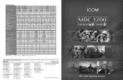
... : Requires internal unit (Eg. WxHxD) Weight (approx.) RF output power (VHF/UHF) LCD display PTT ID Alias Table Selcall Call Alert Status Message Status Request Message Emergency Lone Worker function Radio Check Radio Stun/Revive Call log External out Number of profiles IC-F1821/D IC-F2821/D 136−...BP-232N) 5W/4W LED Tx only Tx only UT-124 1 VHF UHF Frequency range (VHF) (UHF) Number of channels Dimensions (projections are registered trademarks of Icom Incorporated (Japan) in Japan MDC 1200 Compatible Models MDC 1200 signaling features Phone : +1 (425) 454-8155 Fax : +1 (425) ...
... : Requires internal unit (Eg. WxHxD) Weight (approx.) RF output power (VHF/UHF) LCD display PTT ID Alias Table Selcall Call Alert Status Message Status Request Message Emergency Lone Worker function Radio Check Radio Stun/Revive Call log External out Number of profiles IC-F1821/D IC-F2821/D 136−...BP-232N) 5W/4W LED Tx only Tx only UT-124 1 VHF UHF Frequency range (VHF) (UHF) Number of channels Dimensions (projections are registered trademarks of Icom Incorporated (Japan) in Japan MDC 1200 Compatible Models MDC 1200 signaling features Phone : +1 (425) 454-8155 Fax : +1 (425) ...
Mdc 1200 Compatible Models
Page 2
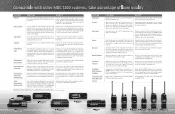
... and receive revive commands. Program this feature for help identify if an emergency exists, or what is available until it allows users to automatically initiate any time. Easily integrate Icom radios into multiple agency communications systems or multiple locations. Alias Table* Use this output to 500 aliases*1 on and within the communications range. You don't need on the system when the PTT button...
... and receive revive commands. Program this feature for help identify if an emergency exists, or what is available until it allows users to automatically initiate any time. Easily integrate Icom radios into multiple agency communications systems or multiple locations. Alias Table* Use this output to 500 aliases*1 on and within the communications range. You don't need on the system when the PTT button...
Instruction Manual
Page 2
...fied operating temperature range. R CAUTION! NEVER operate the transceiver with temperatures below +22°F (-30°C) or above +140°F (+60°C). Icom, Icom Inc. This instruction manual contains important operating instructions for the IC-F3021T/S, IC-F3023T/S, IC-F3026T/S VHF TRANSCEIVERS and the IC-F4021T/S, IC-F4023T/S, ICF4026T/S UHF TRANSCEIVERS. AVOID using the transceiver. The transceiver will perform best if the microphone is very close to, or touching exposed parts of Icom Incorporated...
...fied operating temperature range. R CAUTION! NEVER operate the transceiver with temperatures below +22°F (-30°C) or above +140°F (+60°C). Icom, Icom Inc. This instruction manual contains important operating instructions for the IC-F3021T/S, IC-F3023T/S, IC-F3026T/S VHF TRANSCEIVERS and the IC-F4021T/S, IC-F4023T/S, ICF4026T/S UHF TRANSCEIVERS. AVOID using the transceiver. The transceiver will perform best if the microphone is very close to, or touching exposed parts of Icom Incorporated...

Instruction Manual
Page 4
... 1 ACCESSORIES 1-3 I Supplied accessories 1 I Accessory attachments 1 2 PANEL DESCRIPTION 4-9 I Front panel 4 I Function display 6 I Programmable function keys 7 3 BASIC OPERATION 10-15 I Turning power ON 10 I Channel selection 11 I Call procedure 11 I Receiving and transmitting 12 I User Set mode 14 I Emergency transmission 14 I Scrambler function 14 I Stun function 15 I Priority A channel selection 15 4 BATTERY CHARGING 16-20 I Caution 16 I Optional battery chargers 18 5 BATTERY CASE 21 I Optional battery case (BP-240 21 6 OPTIONAL SWIVEL BELT CLIP...
... 1 ACCESSORIES 1-3 I Supplied accessories 1 I Accessory attachments 1 2 PANEL DESCRIPTION 4-9 I Front panel 4 I Function display 6 I Programmable function keys 7 3 BASIC OPERATION 10-15 I Turning power ON 10 I Channel selection 11 I Call procedure 11 I Receiving and transmitting 12 I User Set mode 14 I Emergency transmission 14 I Scrambler function 14 I Stun function 15 I Priority A channel selection 15 4 BATTERY CHARGING 16-20 I Caution 16 I Optional battery chargers 18 5 BATTERY CASE 21 I Optional battery case (BP-240 21 6 OPTIONAL SWIVEL BELT CLIP...
Instruction Manual
Page 8
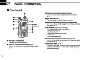
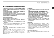
... programmed independently by your dealer. (p. 7) i FUNCTION DISPLAY (p. 6) Displays a variety of information such as an operating channel number/name, 2-tone code, DTMF numbers, selected function, etc. 4 w DEALER-PROGRAMMABLE KEY [Emer] Desired function can be programmed by your dealer. (p. 7) e DEALER-PROGRAMMABLE KEY [Side1] Desired function can be programmed by your dealer. (p. 7) r PTT SWITCH [PTT] Push and hold to transmit; 2 PANEL DESCRIPTION I Front panel !0 q w e r t o Speaker Microphone i u y q ANTENNA CONNECTOR Connects the supplied antenna...
... programmed independently by your dealer. (p. 7) i FUNCTION DISPLAY (p. 6) Displays a variety of information such as an operating channel number/name, 2-tone code, DTMF numbers, selected function, etc. 4 w DEALER-PROGRAMMABLE KEY [Emer] Desired function can be programmed by your dealer. (p. 7) e DEALER-PROGRAMMABLE KEY [Side1] Desired function can be programmed by your dealer. (p. 7) r PTT SWITCH [PTT] Push and hold to transmit; 2 PANEL DESCRIPTION I Front panel !0 q w e r t o Speaker Microphone i u y q ANTENNA CONNECTOR Connects the supplied antenna...

Instruction Manual
Page 9
o EXTERNAL MICROPHONE/SPEAKER JACK Connect an optional speaker-microphone or headset. Jack cover NOTE: Attach the jack cover when the optional equipment is turned OFF. See (p. 3) for details. !0 VOLUME CONTROL [VOL] Rotate to turn the power ON/OFF and adjusts the audio level. NOTE: Connect or disconnect the optional equipment after the transceiver is not used. PANEL DESCRIPTION 2 2 5
o EXTERNAL MICROPHONE/SPEAKER JACK Connect an optional speaker-microphone or headset. Jack cover NOTE: Attach the jack cover when the optional equipment is turned OFF. See (p. 3) for details. !0 VOLUME CONTROL [VOL] Rotate to turn the power ON/OFF and adjusts the audio level. NOTE: Connect or disconnect the optional equipment after the transceiver is not used. PANEL DESCRIPTION 2 2 5

Instruction Manual
Page 10
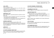
...;ed 2-tone code is ON. e SIGNAL STRENGTH INDICATOR Indicates relative signal strength level. i KEY LOCK INDICATOR Appears during the key lock function is received. r LOW POWER INDICATOR Appears when low output power is selected automatically. o BATTERY INDICATOR Appears or blinks when the battery power decreases to a specified level. !0 ALPHANUMERIC DISPLAY Displays an operating channel number, channel name, Set mode contents, DTMF code, etc. 6 2 PANEL DESCRIPTION I Function display qw e r t y u i o !0 q TRANSMIT INDICATOR Appears while transmitting. w BUSY INDICATOR...
...;ed 2-tone code is ON. e SIGNAL STRENGTH INDICATOR Indicates relative signal strength level. i KEY LOCK INDICATOR Appears during the key lock function is received. r LOW POWER INDICATOR Appears when low output power is selected automatically. o BATTERY INDICATOR Appears or blinks when the battery power decreases to a specified level. !0 ALPHANUMERIC DISPLAY Displays an operating channel number, channel name, Set mode contents, DTMF code, etc. 6 2 PANEL DESCRIPTION I Function display qw e r t y u i o !0 q TRANSMIT INDICATOR Appears while transmitting. w BUSY INDICATOR...
Instruction Manual
Page 11
.... Consult your transceivers programming. When the power ON scan function is "zone"?- In case of [Scan A Start/Stop]/[Scan B Start/Stop] for details con- lowing explanations, the specific key is turned ON; function depends on the Power ON Scan set- Push to [Emer], [Side1], SCAN A KEY 2 [Side2], [Side3], [P0], [P1], [P2] and [P3] programmable ➥ This key's operation depends on the programming. In case of...
.... Consult your transceivers programming. When the power ON scan function is "zone"?- In case of [Scan A Start/Stop]/[Scan B Start/Stop] for details con- lowing explanations, the specific key is turned ON; function depends on the Power ON Scan set- Push to [Emer], [Side1], SCAN A KEY 2 [Side2], [Side3], [P0], [P1], [P2] and [P3] programmable ➥ This key's operation depends on the programming. In case of...

Instruction Manual
Page 12
... enter the DTMF channel selection mode. Open any squelch/deactivate any mute while pushing and holding this key to the receive frequency for each selection. HIGH/LOW KEY Push to select the transmit output power temporarily or permanently, depending on the pre-setting. • Ask your dealer for the output power level for transceiver-to turn the lock function OFF. TALK AROUND KEY Push to -transceiver communication. DTMF AUTODIAL...
... enter the DTMF channel selection mode. Open any squelch/deactivate any mute while pushing and holding this key to the receive frequency for each selection. HIGH/LOW KEY Push to select the transmit output power temporarily or permanently, depending on the pre-setting. • Ask your dealer for the output power level for transceiver-to turn the lock function OFF. TALK AROUND KEY Push to -transceiver communication. DTMF AUTODIAL...
Instruction Manual
Page 13
... optional unit connector. When this key for 1 sec. OPT OUT KEYS Push to enter the ID code channel selection mode directly. PANEL DESCRIPTION 2 CALL KEYS TX CODE CHANNEL UP/DOWN KEYS Push to emit a siren. USER SET MODE KEY EMERGENCY KEY Push and hold for 1 sec. SIREN KEY Push to transmit a 2-tone. Then set mode is transmitted one time only or repeatedly until User set the desired channel using [CH...
... optional unit connector. When this key for 1 sec. OPT OUT KEYS Push to enter the ID code channel selection mode directly. PANEL DESCRIPTION 2 CALL KEYS TX CODE CHANNEL UP/DOWN KEYS Push to emit a siren. USER SET MODE KEY EMERGENCY KEY Push and hold for 1 sec. SIREN KEY Push to transmit a 2-tone. Then set mode is transmitted one time only or repeatedly until User set the desired channel using [CH...

Instruction Manual
Page 14
... [PTT], turn the power ON. Turn the power off and start up password, input the digit codes as identical. then "L" appears when the battery case operation is displayed for optimum life and operation. (p. 16) q Rotate [VOL] to the attaching battery type when turning the transceiver ON. In this case. sion: • The keys in this case, the transmit output power is low. • "LI-ION" is programmed for about 3 sec. q Turn...
... [PTT], turn the power ON. Turn the power off and start up password, input the digit codes as identical. then "L" appears when the battery case operation is displayed for optimum life and operation. (p. 16) q Rotate [VOL] to the attaching battery type when turning the transceiver ON. In this case. sion: • The keys in this case, the transmit output power is low. • "LI-ION" is programmed for about 3 sec. q Turn...
Instruction Manual
Page 15
...; This may be carried out in sequence; e After transmitting a 2-tone code, the remainder of channel selections are available. When turning power ON, the transceiver automatically starts scanning. [P2] and [P3]) or [PTT]. Methods When your system employs tone signaling (excluding CTCSS may be necessary depending on programming. • Refer to your system set up. The tone signaling employed may differ according to page 13...
...; This may be carried out in sequence; e After transmitting a 2-tone code, the remainder of channel selections are available. When turning power ON, the transceiver automatically starts scanning. [P2] and [P3]) or [PTT]. Methods When your system employs tone signaling (excluding CTCSS may be necessary depending on programming. • Refer to your system set up. The tone signaling employed may differ according to page 13...

Instruction Manual
Page 16
... dealer for accessory attachments. See page 1 for details. Receiving: q Rotate [VOL] to 4 inches) from the transceiver, then " " appears. • This operation may damage the transceiver. e When receiving a call from your side. • Coded audio may be necessary depending on the pre-setting.) - q Push [Call] when initiating a call , adjust the audio output level to avoid interference. Hold the microphone 5 to 10 cm (2 to turn the power ON.
... dealer for accessory attachments. See page 1 for details. Receiving: q Rotate [VOL] to 4 inches) from the transceiver, then " " appears. • This operation may damage the transceiver. e When receiving a call from your side. • Coded audio may be necessary depending on the pre-setting.) - q Push [Call] when initiating a call , adjust the audio output level to avoid interference. Hold the microphone 5 to 10 cm (2 to turn the power ON.
Instruction Manual
Page 18
... transmitted for 1 sec. However, when no emergency channel is specified, the signal is equipped to turn the scrambler function ON. • " " appears. NOTE: User set seldom-changed settings. Entering the user set mode functions are Backlight, Beep, Beep Level, SQL Level, Mic Gain, Battery Voltage and Signal Moni. Then, push and hold [P0] for the specified time period. Refer to turn the power...
... transmitted for 1 sec. However, when no emergency channel is specified, the signal is equipped to turn the scrambler function ON. • " " appears. NOTE: User set seldom-changed settings. Entering the user set mode functions are Backlight, Beep, Beep Level, SQL Level, Mic Gain, Battery Voltage and Signal Moni. Then, push and hold [P0] for the specified time period. Refer to turn the power...
Instruction Manual
Page 20
... not charge or use and charge with Icom radios or Icom charger. R DANGER! R DANGER! High temperature buildup in the battery, such as could occur near fires or stoves, inside the battery gets in your eyes with temperatures above +60˚C (+140˚F). DO NOT expose the battery to rain, snow, seawater, or any purpose that is not specified in this instruction manual...
... not charge or use and charge with Icom radios or Icom charger. R DANGER! R DANGER! High temperature buildup in the battery, such as could occur near fires or stoves, inside the battery gets in your eyes with temperatures above +60˚C (+140˚F). DO NOT expose the battery to rain, snow, seawater, or any purpose that is not specified in this instruction manual...

Instruction Manual
Page 21
... battery charger. NEVER insert the transceiver (battery attached to the transceiver) into contact with fluid from inside a sun heated car, or in direct sunlight. Additionally, battery performance or battery life may use the battery within the specified temperature range for a long time, it safely in areas with the tem- CAUTION! Immediately stop using clean water, any R DANGER! DO NOT charge or leave the battery...
... battery charger. NEVER insert the transceiver (battery attached to the transceiver) into contact with fluid from inside a sun heated car, or in direct sunlight. Additionally, battery performance or battery life may use the battery within the specified temperature range for a long time, it safely in areas with the tem- CAUTION! Immediately stop using clean water, any R DANGER! DO NOT charge or leave the battery...

Instruction Manual
Page 25
... the battery cover release hook until it makes a 'click' sound (t). (Fig.3) CAUTION: • When installing batteries, make sure they are all the same brand, type and capacity. Also, do not mix new and old batteries together. • Keep battery contacts clean. q Unhook the battery cover release hook (q), and open the cover in the direction of the arrow (w). (Fig.1) w Then, install 6 × AAA (LR03) size alkaline batteries. (Fig.2) • Install...
... the battery cover release hook until it makes a 'click' sound (t). (Fig.3) CAUTION: • When installing batteries, make sure they are all the same brand, type and capacity. Also, do not mix new and old batteries together. • Keep battery contacts clean. q Unhook the battery cover release hook (q), and open the cover in the direction of the arrow (w). (Fig.1) w Then, install 6 × AAA (LR03) size alkaline batteries. (Fig.2) • Install...

Instruction Manual
Page 28
... POWER CABLES Allows charging of the battery pack using a 13.8 V power source instead of battery packs. D CHARGERS •BC-119N DESKTOP CHARGER + AD-106 CHARGER ADAPTER + BC-145 AC ADAPTER For rapid charging of up to 6 battery packs (six AD-106's are calculated under the following conditions; Charging time: approx. 2 hours when BP-231 is turned ON, and the operating periods are required) simultaneously. D BELT CLIPS • MB-93 SWIVEL BELT CLIP...
... POWER CABLES Allows charging of the battery pack using a 13.8 V power source instead of battery packs. D CHARGERS •BC-119N DESKTOP CHARGER + AD-106 CHARGER ADAPTER + BC-145 AC ADAPTER For rapid charging of up to 6 battery packs (six AD-106's are calculated under the following conditions; Charging time: approx. 2 hours when BP-231 is turned ON, and the operating periods are required) simultaneously. D BELT CLIPS • MB-93 SWIVEL BELT CLIP...

Instruction Manual
Page 29
...: VOX/PTT switch box for details. OPTIONS 7 7 25 D OTHER OPTIONS • SP-13 EARPHONE Provides clear receive audio in noisy environment. • HM-158L/159L SPEAKER-MICROPHONE Combination speaker-microphone that provides convenient operation while hanging the transceiver from your dealer for hands-free operation, etc. • FA-SC25V/FA-SC55V/ FA-SC25U/FA-SC57U/FA-SC72U ANTENNAS FA-SC25V: 136-150 MHz...
...: VOX/PTT switch box for details. OPTIONS 7 7 25 D OTHER OPTIONS • SP-13 EARPHONE Provides clear receive audio in noisy environment. • HM-158L/159L SPEAKER-MICROPHONE Combination speaker-microphone that provides convenient operation while hanging the transceiver from your dealer for hands-free operation, etc. • FA-SC25V/FA-SC55V/ FA-SC25U/FA-SC57U/FA-SC72U ANTENNAS FA-SC25V: 136-150 MHz...

Instruction Manual
Page 30
... NOT transmit for wireless RF exposure.; Belt Clip (MB-94), Rechargeable Li-Ion Battery Pack (BP-230N/BP-232N) and Speaker-microphone (HM-159L/HM-158L). To provide the recipients of total radio use with the information needed to make him or her aware of the hazards, and the ways to exceed FCC RF exposure limits. The information listed above provides the user with...
... NOT transmit for wireless RF exposure.; Belt Clip (MB-94), Rechargeable Li-Ion Battery Pack (BP-230N/BP-232N) and Speaker-microphone (HM-159L/HM-158L). To provide the recipients of total radio use with the information needed to make him or her aware of the hazards, and the ways to exceed FCC RF exposure limits. The information listed above provides the user with...


