
Instruction Manual
Page 1
IC-A24 IC-A6 INSTRUCTION MANUAL VHF AIR BAND TRANSCEIVER iA24 iA6 This device complies with Part 15 of the FCC Rules. Operation is subject to the condition that this device does not cause harmful interference.
IC-A24 IC-A6 INSTRUCTION MANUAL VHF AIR BAND TRANSCEIVER iA24 iA6 This device complies with Part 15 of the FCC Rules. Operation is subject to the condition that this device does not cause harmful interference.
Instruction Manual
Page 2
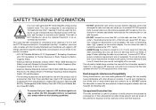
...authorized by pressing the "PTT" switch. • ALWAYS keep the antenna at least 2.5 cm (1 inch) away from your Icom radio generates RF energy that are sensitive to RF energy and electromagnetic energy levels and evaluation of Potentially Hazardous Electromagnetic Fields- Electromagnetic...consequence of 2.5 cm with the FCC RF exposure limits of RF exposure, and what to do so. SAFETY TRAINING INFORMATION Your Icom radio generates RF electromagnetic energy during transmit mode. This radio has been evaluated for ex- A proper antenna is transmitting when "...
...authorized by pressing the "PTT" switch. • ALWAYS keep the antenna at least 2.5 cm (1 inch) away from your Icom radio generates RF energy that are sensitive to RF energy and electromagnetic energy levels and evaluation of Potentially Hazardous Electromagnetic Fields- Electromagnetic...consequence of 2.5 cm with the FCC RF exposure limits of RF exposure, and what to do so. SAFETY TRAINING INFORMATION Your Icom radio generates RF electromagnetic energy during transmit mode. This radio has been evaluated for ex- A proper antenna is transmitting when "...
Instruction Manual
Page 3
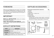
With proper care this product should provide you for the IC-A24/A6. q Antenna 1 w Belt clip 1 e Handstrap 1 r Battery pack* or battery case 1 t Wall charger 1 y Carrying case 1 u Headset adapter 1 * The battery pack, wall charger, headset.... CAUTION Equipment damage may occur. IMPORTANT READ ALL INSTRUCTIONS carefully and completely before using the transceiver. The IC-A24/A6 VHF AIR BAND TRANSCEIVER is designed and built with Icom's state of personal injury, fire or electric shock. Some versions do not include a battery pack, wall charger, headset adapter or ...
With proper care this product should provide you for the IC-A24/A6. q Antenna 1 w Belt clip 1 e Handstrap 1 r Battery pack* or battery case 1 t Wall charger 1 y Carrying case 1 u Headset adapter 1 * The battery pack, wall charger, headset.... CAUTION Equipment damage may occur. IMPORTANT READ ALL INSTRUCTIONS carefully and completely before using the transceiver. The IC-A24/A6 VHF AIR BAND TRANSCEIVER is designed and built with Icom's state of personal injury, fire or electric shock. Some versions do not include a battery pack, wall charger, headset adapter or ...
Instruction Manual
Page 4
...60°C (+140°F). DO NOT allow children to this transceiver, not expressly approved by this transceiver under FCC regulations. (U.S.A. Icom, Icom Inc. The transceiver will Even when the transceiver power is the transceiver when not using or placing the transceiver in direct sunlight or... headset or other countries. The use . Therefore, be protected by Icom Inc., could void your ears, reduce the volume level or discontinue use of the battery pack. R WARNING! If you experience a ...
...60°C (+140°F). DO NOT allow children to this transceiver, not expressly approved by this transceiver under FCC regulations. (U.S.A. Icom, Icom Inc. The transceiver will Even when the transceiver power is the transceiver when not using or placing the transceiver in direct sunlight or... headset or other countries. The use . Therefore, be protected by Icom Inc., could void your ears, reduce the volume level or discontinue use of the battery pack. R WARNING! If you experience a ...

Instruction Manual
Page 5
... 24 7 BATTERY PACKS 25 - 27 I Battery charging 25 I Battery cautions 25 I Optional battery case 26 I Duplex operation (U.S.A. version only 17 I "TAG" channels 17 6 VOR NAVIGATION (IC-A24 only 18 - 24 I VOR indications 18 I VOR functions 19 I Flying to a VOR station 20 I Entering a desired course 22 I Crosschecking position 22 I Optional battery chargers 27...
... 24 7 BATTERY PACKS 25 - 27 I Battery charging 25 I Battery cautions 25 I Optional battery case 26 I Duplex operation (U.S.A. version only 17 I "TAG" channels 17 6 VOR NAVIGATION (IC-A24 only 18 - 24 I VOR indications 18 I VOR functions 19 I Flying to a VOR station 20 I Entering a desired course 22 I Crosschecking position 22 I Optional battery chargers 27...
Instruction Manual
Page 7
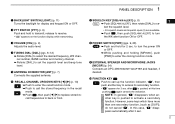
u SQUELCH KEY [SQL•WX-ALERT] (p. 8) 1 ➥ Push [SQL•WX-ALERT], then rotate [DIAL] to enter the cloning function mode. to turn the WX-alert function ON or OFF. PANEL DESCRIPTION 1 q BACKLIGHT SWITCH [LIGHT] (p. 11) Turns the backlight for 2 sec. at this case, " " disappears automatically after is pushed to activate a secondary function. lect the squelch level. • 24 squelch levels and squelch open (0) are available. ➥ Push , then push [SQL•WX-ALERT] to set the squelch level and beep tone level. e VOLUME [VOL] (p. 9) Adjusts the audio ...
u SQUELCH KEY [SQL•WX-ALERT] (p. 8) 1 ➥ Push [SQL•WX-ALERT], then rotate [DIAL] to enter the cloning function mode. to turn the WX-alert function ON or OFF. PANEL DESCRIPTION 1 q BACKLIGHT SWITCH [LIGHT] (p. 11) Turns the backlight for 2 sec. at this case, " " disappears automatically after is pushed to activate a secondary function. lect the squelch level. • 24 squelch levels and squelch open (0) are available. ➥ Push , then push [SQL•WX-ALERT] to set the squelch level and beep tone level. e VOLUME [VOL] (p. 9) Adjusts the audio ...

Instruction Manual
Page 8
.... ➥ Push , then push [MR•MW] to enter the weather channel selection mode (U.S.A. to select the 121.5 MHz emergency frequency. • DC POWER CONNECTION IC-A24/A6 CP-20 (for details. !2 ANL KEY [ANL•SCAN] (pgs. 9, 16, 17) ➥ Push to turn to the frequency mode while the scan function...
.... ➥ Push , then push [MR•MW] to enter the weather channel selection mode (U.S.A. to select the 121.5 MHz emergency frequency. • DC POWER CONNECTION IC-A24/A6 CP-20 (for details. !2 ANL KEY [ANL•SCAN] (pgs. 9, 16, 17) ➥ Push to turn to the frequency mode while the scan function...
Instruction Manual
Page 9
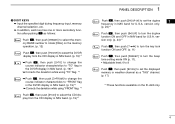
... one or more secondary function after pushing as follows: Push , then push [0•BANK] to select the memory BANK number to rotate [DIAL] on the IC-A24 only. 4 version only. (p. 24)*1 Push , then push [7• ] to turn the key lock function ON and OFF. (p. 11) Push , then push [8•BEEP] to turn...
... one or more secondary function after pushing as follows: Push , then push [0•BANK] to select the memory BANK number to rotate [DIAL] on the IC-A24 only. 4 version only. (p. 24)*1 Push , then push [7• ] to turn the key lock function ON and OFF. (p. 11) Push , then push [8•BEEP] to turn...
Instruction Manual
Page 10
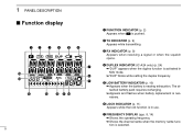
... the channel name when the memory name function is necessary. 1 PANEL DESCRIPTION I Function display qw e r t y u !5 i !4 o !1 !3 !2 !1 !0 5 q FUNCTION INDICATOR (p. 2) Appears when is activated in use. r DUPLEX INDICATOR (IC-A24 only) (p. 24) ➥"DUP" appears when the duplex function is pushed.
... the channel name when the memory name function is necessary. 1 PANEL DESCRIPTION I Function display qw e r t y u !5 i !4 o !1 !3 !2 !1 !0 5 q FUNCTION INDICATOR (p. 2) Appears when is activated in use. r DUPLEX INDICATOR (IC-A24 only) (p. 24) ➥"DUP" appears when the duplex function is pushed.

Instruction Manual
Page 11
...course and your actual flying course every 2 degrees. 6 o MEMORY CHANNEL INDICATOR (pgs. 12-15) Shows the memory channel number. !4 COURSE INDICATORS (IC-A24 only) (p. 19) ➥ Indicates where your aircraft is located on a VOR radial in DVOR mode. ➥Indicates where your desired course is located on... a VOR radial in CDI mode. !0 MEMORY BANK NUMBER INDICATOR (p. 12) Shows the selected memory bank number. !1 OVERFLOW INDICATOR (IC-A24 only) (pgs. 18-22) Appears when the deviation between the desired course and flying course is over 10 degrees. !5 TO-FROM INDICATOR...
...course and your actual flying course every 2 degrees. 6 o MEMORY CHANNEL INDICATOR (pgs. 12-15) Shows the memory channel number. !4 COURSE INDICATORS (IC-A24 only) (p. 19) ➥ Indicates where your aircraft is located on a VOR radial in DVOR mode. ➥Indicates where your desired course is located on... a VOR radial in CDI mode. !0 MEMORY BANK NUMBER INDICATOR (p. 12) Shows the selected memory bank number. !1 OVERFLOW INDICATOR (IC-A24 only) (pgs. 18-22) Appears when the deviation between the desired course and flying course is over 10 degrees. !5 TO-FROM INDICATOR...
Instruction Manual
Page 12
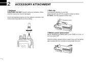
D Belt clip Conveniently attaches to turn the power OFF. NOTE: Use the supplied screws only. Insert the supplied antenna into the antenna connector and screw down the antenna as below . Supplied screws D Battery pack replacement Before replacing the battery pack, push [PWR] for 2 sec. Other- Slide the battery release button forward, then pull the battery pack upward with the supplied screws as shown below . Attach the belt clip with the transceiver facing away from you. 7 2 ACCESSORY ATTACHMENT D Antenna CAUTION: DO NOT transmit without an antenna. to your belt. wise ...
D Belt clip Conveniently attaches to turn the power OFF. NOTE: Use the supplied screws only. Insert the supplied antenna into the antenna connector and screw down the antenna as below . Supplied screws D Battery pack replacement Before replacing the battery pack, push [PWR] for 2 sec. Other- Slide the battery release button forward, then pull the battery pack upward with the supplied screws as shown below . Attach the belt clip with the transceiver facing away from you. 7 2 ACCESSORY ATTACHMENT D Antenna CAUTION: DO NOT transmit without an antenna. to your belt. wise ...

Instruction Manual
Page 13
squelch level. w Push [SQL•WX-ALERT] or [CLR•DEL] to set mode. w Rotate [DIAL] to exit the squelch set the desired frequency. play . version has VHF marine WX (weather) channel receiving capability for 2 sec. 3 BASIC OPERATION I Setting a frequency I Selecting a weather channel (U.S.A. then repeat step w again. • Push [ENT•WX] to mute undesired 2 q Push [PWR] for 2 sec. w Rotate [DIAL] to frequency mode. • To select the 1 MHz tuning step, push , then rotate [DIAL]. e Push [CLR•DEL] to exit the WX channel mode and return to ...
squelch level. w Push [SQL•WX-ALERT] or [CLR•DEL] to set mode. w Rotate [DIAL] to exit the squelch set the desired frequency. play . version has VHF marine WX (weather) channel receiving capability for 2 sec. 3 BASIC OPERATION I Setting a frequency I Selecting a weather channel (U.S.A. then repeat step w again. • Push [ENT•WX] to mute undesired 2 q Push [PWR] for 2 sec. w Rotate [DIAL] to frequency mode. • To select the 1 MHz tuning step, push , then rotate [DIAL]. e Push [CLR•DEL] to exit the WX channel mode and return to ...
Instruction Manual
Page 14
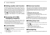
e Rotate [VOL] to receive. If the frequency is busy, wait until the noise is clear. t Set the desired frequency using [DIAL] or keypad. • COM band frequency range: 118.00-136.975 MHz w Push and hold the transceiver too close to your mouth or speak too loudly. I ANL function The ANL (Automatic Noise Limiter) function reduces noise components such as that caused by engine ignition systems while receiving. • Push [ANL•SCAN] to turn the power ON. r Push [SQL•WX-ALERT], then rotate [DIAL] clockwise until the channel is muted. • " " indicator ...
e Rotate [VOL] to receive. If the frequency is busy, wait until the noise is clear. t Set the desired frequency using [DIAL] or keypad. • COM band frequency range: 118.00-136.975 MHz w Push and hold the transceiver too close to your mouth or speak too loudly. I ANL function The ANL (Automatic Noise Limiter) function reduces noise components such as that caused by engine ignition systems while receiving. • Push [ANL•SCAN] to turn the power ON. r Push [SQL•WX-ALERT], then rotate [DIAL] clockwise until the channel is muted. • " " indicator ...

Instruction Manual
Page 15
to delete it . • Replaces the selected channel into the previous channel when push , then . • Replaces the selected channel into the behind channel when push , then . • (e.g.) Replaces "r0" which is stored 121.375 MHz into "r1". D Deletes the stored recall channel q Push or to a specified level. D Replaces the stored recall channel q Push w Push or to select the replacing recall channel. , then push or to call the 10th stored frequency. w Push , then push [CLR•DEL] for 2 sec. The function stores frequencies when the frequency is ...
to delete it . • Replaces the selected channel into the previous channel when push , then . • Replaces the selected channel into the behind channel when push , then . • (e.g.) Replaces "r0" which is stored 121.375 MHz into "r1". D Deletes the stored recall channel q Push or to a specified level. D Replaces the stored recall channel q Push w Push or to select the replacing recall channel. , then push or to call the 10th stored frequency. w Push , then push [CLR•DEL] for 2 sec. The function stores frequencies when the frequency is ...
Instruction Manual
Page 16
... a weather alert tone be set the beep level. w During transmit mode, rotate [DIAL] to the 121.5 MHz emergency frequency. level. A ringing in use . The IC-A24 and IC-A6 can quickly gain access to adjust the monitor- I Setting beep tone vated even when the key lock function is in your transmitted voice to...
... a weather alert tone be set the beep level. w During transmit mode, rotate [DIAL] to the 121.5 MHz emergency frequency. level. A ringing in use . The IC-A24 and IC-A6 can quickly gain access to adjust the monitor- I Setting beep tone vated even when the key lock function is in your transmitted voice to...

Instruction Manual
Page 17
4 MEMORY OPERATION I Memory channel selection I Transferring memory The transceiver has 200 memory channels for signals 4 • Memory BANK number and memory CH. number. • If no memory CH. is available. q Push [MR•MW] to dis- w Select the desired memory channel to be programmed by your dealer to show the operating frequency first. selection is programmed in the selected BANK, no memory CH. NOTE: Comments appear first when programmed, how- Push [MR•MW] to select memory mode. q Push [MR•MW] to transfer the memory channel's ...
4 MEMORY OPERATION I Memory channel selection I Transferring memory The transceiver has 200 memory channels for signals 4 • Memory BANK number and memory CH. number. • If no memory CH. is available. q Push [MR•MW] to dis- w Select the desired memory channel to be programmed by your dealer to show the operating frequency first. selection is programmed in the selected BANK, no memory CH. NOTE: Comments appear first when programmed, how- Push [MR•MW] to select memory mode. q Push [MR•MW] to transfer the memory channel's ...

Instruction Manual
Page 18
e Push , then push [MR•MW] to program the contents into the channel and return to the frequency mode. *Weather channel: U.S.A. Push Push or Push Push Push (or rotate [DIAL]) Push or Push or (or rotate [DIAL]) Push 13 r Rotate [DIAL] to select the desired memory channel number. • Push , then push [0•BANK] to select the BANK number if desired. • Push [CLR•DEL], [ENT•WX] or , then push [0•BANK] to select a weather channel.* • Set the desired frequency or weather channel* using [DIAL] or keypad. t Push [ENT•WX] to select ...
e Push , then push [MR•MW] to program the contents into the channel and return to the frequency mode. *Weather channel: U.S.A. Push Push or Push Push Push (or rotate [DIAL]) Push or Push or (or rotate [DIAL]) Push 13 r Rotate [DIAL] to select the desired memory channel number. • Push , then push [0•BANK] to select the BANK number if desired. • Push [CLR•DEL], [ENT•WX] or , then push [0•BANK] to select a weather channel.* • Set the desired frequency or weather channel* using [DIAL] or keypad. t Push [ENT•WX] to select ...

Instruction Manual
Page 19
I 5 5, J, K, L 6 6, M, N, O 4 q Rotate [DIAL] to be cleared. r Push [MR•MW] to exit the BANK selection mode. Push [CLR•DEL] to enter the memory name programming mode appears on the display. appears momentarily, then the next selectable channel appears. 14 e Rotate [DIAL] to select the desired memory channel to be programmed. • Push [0•BANK] to program the name. • Flashing the memory name stops. • When no name is programmed, the display shows the operating frequency. • To clear the programmed memory names, push [CLR•...
I 5 5, J, K, L 6 6, M, N, O 4 q Rotate [DIAL] to be cleared. r Push [MR•MW] to exit the BANK selection mode. Push [CLR•DEL] to enter the memory name programming mode appears on the display. appears momentarily, then the next selectable channel appears. 14 e Rotate [DIAL] to select the desired memory channel to be programmed. • Push [0•BANK] to program the name. • Flashing the memory name stops. • When no name is programmed, the display shows the operating frequency. • To clear the programmed memory names, push [CLR•...

Instruction Manual
Page 20
Push Push Push Push Push Push Push Push Push Push NOTE: Push [0•BANK], then rotate [DIAL] to continue memory name programming. 15 4 MEMORY OPERATION • EXAMPLE: Programming 125.000 MHz into memory BANK 1/ memory channel 17 with "AIR-23" as a comment. Push [CLR•DEL] to select the BANK number, if desired.
Push Push Push Push Push Push Push Push Push Push NOTE: Push [0•BANK], then rotate [DIAL] to continue memory name programming. 15 4 MEMORY OPERATION • EXAMPLE: Programming 125.000 MHz into memory BANK 1/ memory channel 17 with "AIR-23" as a comment. Push [CLR•DEL] to select the BANK number, if desired.

Instruction Manual
Page 21
non-U.S.A. r To stop the scan, push [CLR•DEL]. versions have 2 scan types. 5 SCAN OPERATION I Scan types I Memory scan MEMORY SCAN non-TAG channel Mch 2 Mch 4 Mch 6 Mch 1 Mch 19 Mch 10 Mch 7 non-TAG Mch 8 channel Repeatedly scans all "TAG" weather channels. Jump I COM band scan The U.S.A. WEATHER CHANNEL SCAN Repeatedly scans all "TAG" memory channels. version has 3 scan types to select memory mode. e Push , then push [ANL•SCAN] to start the scan. • When a signal is just muted. e Push , then push [ANL•SCAN] to the point COM...
non-U.S.A. r To stop the scan, push [CLR•DEL]. versions have 2 scan types. 5 SCAN OPERATION I Scan types I Memory scan MEMORY SCAN non-TAG channel Mch 2 Mch 4 Mch 6 Mch 1 Mch 19 Mch 10 Mch 7 non-TAG Mch 8 channel Repeatedly scans all "TAG" weather channels. Jump I COM band scan The U.S.A. WEATHER CHANNEL SCAN Repeatedly scans all "TAG" memory channels. version has 3 scan types to select memory mode. e Push , then push [ANL•SCAN] to start the scan. • When a signal is just muted. e Push , then push [ANL•SCAN] to the point COM...
