Instruction Manual
Page 2
...- tery Case (BP-208N). • DO NOT operate the radio without a proper antenna attached, as consequence of RF exposure, and what to Radio Frequency Elec- C AU TIO N i SAFETY TRAINING INFORMATION Your Icom radio generates RF electromagnetic energy during transmit mode. posure to humans: • FCC OET...the time can possibly cause interference with the FCC RF exposure limits of employment by pressing the "PTT" switch. • ALWAYS keep the antenna at least 2.5 cm (1 inch) away from your belt, etc., to ensure FCC RF exposure compliance requirements are posted to do to exceed...
...- tery Case (BP-208N). • DO NOT operate the radio without a proper antenna attached, as consequence of RF exposure, and what to Radio Frequency Elec- C AU TIO N i SAFETY TRAINING INFORMATION Your Icom radio generates RF electromagnetic energy during transmit mode. posure to humans: • FCC OET...the time can possibly cause interference with the FCC RF exposure limits of employment by pressing the "PTT" switch. • ALWAYS keep the antenna at least 2.5 cm (1 inch) away from your belt, etc., to ensure FCC RF exposure compliance requirements are posted to do to exceed...
Instruction Manual
Page 3
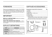
... ALL INSTRUCTIONS carefully and completely before using the transceiver. struction manual contains important operating instructions for purchasing this product should provide you for the IC-A24/A6. This in- q Antenna 1 w Belt clip 1 e Handstrap 1 r Battery pack* or battery case 1 t Wall charger 1 y Carrying case 1 u Headset adapter 1 * The ...or carrying case. ii FOREWORD SUPPLIED ACCESSORIES Thank you with years of trouble-free operation. With proper care this Icom product. Accessories included with Icom's state of personal injury, fire or electric shock.
... ALL INSTRUCTIONS carefully and completely before using the transceiver. struction manual contains important operating instructions for purchasing this product should provide you for the IC-A24/A6. This in- q Antenna 1 w Belt clip 1 e Handstrap 1 r Battery pack* or battery case 1 t Wall charger 1 y Carrying case 1 u Headset adapter 1 * The ...or carrying case. ii FOREWORD SUPPLIED ACCESSORIES Thank you with years of trouble-free operation. With proper care this Icom product. Accessories included with Icom's state of personal injury, fire or electric shock.
Instruction Manual
Page 4
...placing the transceiver in the United States, the United Kingdom, Germany, France, Spain, Russia and/or other audio accessories at more than 5 A. Icom, Icom Inc. DO NOT operate the transceiver near metal objects, carrying in your authority to , or touching exposed parts of more than 11.5 V DC... while transmitting. FCC caution: Changes or modifications to 10 cm away from NEVER connect the transceiver to a power source that the antenna is vertical. in areas with a AVOID using it for a long time. only) rent may impair NEVER connect the transceiver to an AC...
...placing the transceiver in the United States, the United Kingdom, Germany, France, Spain, Russia and/or other audio accessories at more than 5 A. Icom, Icom Inc. DO NOT operate the transceiver near metal objects, carrying in your authority to , or touching exposed parts of more than 11.5 V DC... while transmitting. FCC caution: Changes or modifications to 10 cm away from NEVER connect the transceiver to a power source that the antenna is vertical. in areas with a AVOID using it for a long time. only) rent may impair NEVER connect the transceiver to an AC...
Instruction Manual
Page 7
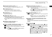
...; Rotate [DIAL] to select the desired frequency, WX channel number, BANK number and memory channel. ➥Rotate [DIAL] to se- release to transmit; t ANTENNA CONNECTOR [ANT] (p. 7) Connects the supplied antenna. to back or front. at this case, " " disappears automatically after is pushed to access its secondary function. • " " appears for 3 sec. In...
...; Rotate [DIAL] to select the desired frequency, WX channel number, BANK number and memory channel. ➥Rotate [DIAL] to se- release to transmit; t ANTENNA CONNECTOR [ANT] (p. 7) Connects the supplied antenna. to back or front. at this case, " " disappears automatically after is pushed to access its secondary function. • " " appears for 3 sec. In...
Instruction Manual
Page 12
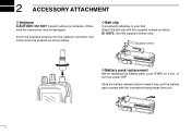
...damaged. NOTE: Use the supplied screws only. D Belt clip Conveniently attaches to turn the power OFF. Insert the supplied antenna into the antenna connector and screw down the antenna as below . Supplied screws D Battery pack replacement Before replacing the battery pack, push [PWR] for 2 sec. ...2 ACCESSORY ATTACHMENT D Antenna CAUTION: DO NOT transmit without an antenna. Slide the battery release button forward, then pull the battery pack upward...
...damaged. NOTE: Use the supplied screws only. D Belt clip Conveniently attaches to turn the power OFF. Insert the supplied antenna into the antenna connector and screw down the antenna as below . Supplied screws D Battery pack replacement Before replacing the battery pack, push [PWR] for 2 sec. ...2 ACCESSORY ATTACHMENT D Antenna CAUTION: DO NOT transmit without an antenna. Slide the battery release button forward, then pull the battery pack upward...
Instruction Manual
Page 14
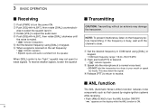
... hold [PTT] to turn the ANL function ON/OFF. r Release [PTT] to return to select the squelch level 0. 3 BASIC OPERATION I Transmitting CAUTION: Transmitting without an antenna may damage the transceiver. When [SQL] control is emitted from the speaker. " " appears on the frequency before transmitting. e Rotate [VOL] to turn the power ON...
... hold [PTT] to turn the ANL function ON/OFF. r Release [PTT] to return to select the squelch level 0. 3 BASIC OPERATION I Transmitting CAUTION: Transmitting without an antenna may damage the transceiver. When [SQL] control is emitted from the speaker. " " appears on the frequency before transmitting. e Rotate [VOL] to turn the power ON...
Instruction Manual
Page 35
...mA typical (at stand by) 2nd 450 kHz 300 mA typical.(at AF max.) •Sensitivity VOR (AM 6dB S/N): Less than -3 dBµ typical • Antenna connector : BNC 50 Ω (nominal) • Dimensions : 54(W)×129.3(H)×35.5(D) mm (projections not incl.) 21⁄8(W) × 53⁄32(H) &#...SPECIFICATIONS D General D Transmitter • Frequency coverage (MHz): TX 118.000 to 136.975 RX 108.000 to 136.975*1 WX 161.650 to 163.275*2 *1: IC-A24 only, IC-A6; 118.000 to 100% : Less than 10% (at60 % mod.) : More than 35 dB : More than 46 dB (except oper- version only. ...
...mA typical (at stand by) 2nd 450 kHz 300 mA typical.(at AF max.) •Sensitivity VOR (AM 6dB S/N): Less than -3 dBµ typical • Antenna connector : BNC 50 Ω (nominal) • Dimensions : 54(W)×129.3(H)×35.5(D) mm (projections not incl.) 21⁄8(W) × 53⁄32(H) &#...SPECIFICATIONS D General D Transmitter • Frequency coverage (MHz): TX 118.000 to 136.975 RX 108.000 to 136.975*1 WX 161.650 to 163.275*2 *1: IC-A24 only, IC-A6; 118.000 to 100% : Less than 10% (at60 % mod.) : More than 35 dB : More than 46 dB (except oper- version only. ...
