User Guide
Page 5
... address 16 Setting the date and time 17 © Copyright IBM Corp. 2008 iii Introducing the SAN40B-4 switch 1 Features and functions of the switch 1 Supported connectivity 2 Port side of the switch 2 Port numbering 3 Nonport side of the switch 4 Field replaceable units (FRUs 4 Additional port activation 4 ISL Trunking groups 5 Supported optional features 5 Chapter 2. Installing and configuring the...
... address 16 Setting the date and time 17 © Copyright IBM Corp. 2008 iii Introducing the SAN40B-4 switch 1 Features and functions of the switch 1 Supported connectivity 2 Port side of the switch 2 Port numbering 3 Nonport side of the switch 4 Field replaceable units (FRUs 4 Additional port activation 4 ISL Trunking groups 5 Supported optional features 5 Chapter 2. Installing and configuring the...
User Guide
Page 6
...POST and boot specifications 25 POST 25 Boot 25 Interpreting POST results 26 Maintaining the switch 26 Installing SFPs 26 Diagnostic tests 30 Customer field replaceable units (CRUs/FRUs 31 ...37 Fibre Channel port specifications 38 Serial port specifications 38 Power supply specifications 38 Supported SFPs and HBAs 39 System specifications 39 Notices 41 Trademarks 43 Electronic emission notices 44 Federal Communications Commission (FCC) Class A Statement ... 46 Korea Class A Electronic Emission Statement 46 Index 47 iv SAN40B-4 Installation, Service, and User's Guide Chapter 3.
...POST and boot specifications 25 POST 25 Boot 25 Interpreting POST results 26 Maintaining the switch 26 Installing SFPs 26 Diagnostic tests 30 Customer field replaceable units (CRUs/FRUs 31 ...37 Fibre Channel port specifications 38 Serial port specifications 38 Power supply specifications 38 Supported SFPs and HBAs 39 System specifications 39 Notices 41 Trademarks 43 Electronic emission notices 44 Federal Communications Commission (FCC) Class A Statement ... 46 Korea Class A Electronic Emission Statement 46 Index 47 iv SAN40B-4 Installation, Service, and User's Guide Chapter 3.

User Guide
Page 7
...on the nonport side of the rail and the locking brackets to the switch 12 7. SFP installation and bail closing 27 12. Non-port side of the switch 2 2. Removing an SFP 29 13. Mounting the fixed portion of the switch 22 11. Location of LEDs on the port side of the slide ...and mounting brackets to the rack 13 8. Fibre Channel port numbering 3 3. Captive screws on the power supply fan assemblies 32 14. Port side of the switch 4 4. Installing a replacement power supply fan assembly 33 © Copyright IBM Corp. 2008 v Figures 1. Mounting the moving portion of the...
...on the nonport side of the rail and the locking brackets to the switch 12 7. SFP installation and bail closing 27 12. Non-port side of the switch 2 2. Removing an SFP 29 13. Mounting the fixed portion of the switch 22 11. Location of LEDs on the port side of the slide ...and mounting brackets to the rack 13 8. Fibre Channel port numbering 3 3. Captive screws on the power supply fan assemblies 32 14. Port side of the switch 4 4. Installing a replacement power supply fan assembly 33 © Copyright IBM Corp. 2008 v Figures 1. Mounting the moving portion of the...
User Guide
Page 9
...IBM Corp. 2008 vii Brocade and IBM product and model number matrix xx 3. Power status LED patterns, status, and recommended actions 23 5. Port LED patterns during normal operation 24 7. Power supply status LED patterns, status, and recommended actions 25 9. Physical dimensions and weight of the switch... 35 11. Data transmission ranges 37 15. Sample caution notices xii 2. Parts supplied with the rack-mount kit 11 4. Serial cable pinouts 38 16. Ethernet LED patterns 24 8. Tables 1. System status LED patterns, status, and recommended actions 23 6. Switch power...
...IBM Corp. 2008 vii Brocade and IBM product and model number matrix xx 3. Power status LED patterns, status, and recommended actions 23 5. Port LED patterns during normal operation 24 7. Power supply status LED patterns, status, and recommended actions 25 9. Physical dimensions and weight of the switch... 35 11. Data transmission ranges 37 15. Sample caution notices xii 2. Parts supplied with the rack-mount kit 11 4. Serial cable pinouts 38 16. Ethernet LED patterns 24 8. Tables 1. System status LED patterns, status, and recommended actions 23 6. Switch power...
User Guide
Page 21
... by systems administrators and technicians experienced with this document) v IBM System Storage SAN40B-4 Quick Start Guide, GA32-0586 v IBM Systems Safety Notices, G229-9054 v IBM System Storage SAN 2498 Statement of Limited Warranty, GA32-0584 Brocade documents IBM b-type switches use the IBM System Storage™ SAN40B-4 (... OS version. The sections that supports the director in the following documents contain information related to this product: v IBM System Storage SAN40B-4 Installation, Service, and User's Guide, GA32-0581 (this product: Brocade Fabric OS v Fabric OS Administrator's ...
... by systems administrators and technicians experienced with this document) v IBM System Storage SAN40B-4 Quick Start Guide, GA32-0586 v IBM Systems Safety Notices, G229-9054 v IBM System Storage SAN 2498 Statement of Limited Warranty, GA32-0584 Brocade documents IBM b-type switches use the IBM System Storage™ SAN40B-4 (... OS version. The sections that supports the director in the following documents contain information related to this product: v IBM System Storage SAN40B-4 Installation, Service, and User's Guide, GA32-0581 (this product: Brocade Fabric OS v Fabric OS Administrator's ...
User Guide
Page 25
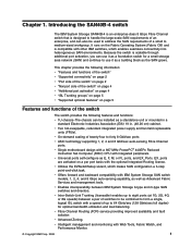
... optional Integrated Routing license. v Fibre Channel Routing (FCR) service providing improved scalability and fault isolation v Advanced Zoning. Introducing the SAN40B-4 switch The IBM System Storage SAN40B-4 is an enterprise-class 8 Gbps Fibre Channel switch that is compatible with IBM System Storage SAN switch models, 1, 2, 4, and 8 Gbps auto-sensing capability, as well as E, F, M, or FL ports, and EX_Ports. v Offers forward and backward...
... optional Integrated Routing license. v Fibre Channel Routing (FCR) service providing improved scalability and fault isolation v Advanced Zoning. Introducing the SAN40B-4 switch The IBM System Storage SAN40B-4 is an enterprise-class 8 Gbps Fibre Channel switch that is compatible with IBM System Storage SAN switch models, 1, 2, 4, and 8 Gbps auto-sensing capability, as well as E, F, M, or FL ports, and EX_Ports. v Offers forward and backward...
User Guide
Page 26
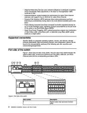
... 38 39 b40_0001 4 Figure 1. Hardware zoning is accomplished at the following web site: www.ibm.com/ servers/storage/support/san. The port side of the switch Item number 1 2 SAN40B-4 Installation, Service, and User's Guide 8 9 10 11 12 13 14 15 Description System status (top) and power (bottom) LEDs v Dynamic Path Selection (DPS) optimizes fabric-wide...
... 38 39 b40_0001 4 Figure 1. Hardware zoning is accomplished at the following web site: www.ibm.com/ servers/storage/support/san. The port side of the switch Item number 1 2 SAN40B-4 Installation, Service, and User's Guide 8 9 10 11 12 13 14 15 Description System status (top) and power (bottom) LEDs v Dynamic Path Selection (DPS) optimizes fabric-wide...

User Guide
Page 27
Introducing the SAN40B-4 switch 3 Chapter 1. Item number 2 3 4 5 6 7 Description System RS232 console port (RJ-45) System Ethernet port (RJ-45) Ethernet port LEDs (green/amber) USB port Fibre Channel port status LED Fibre Channel ports (40) Port numbering The Fibre Channel ports on the switch are numbered from 0 to the Fabric OS Administrator's Guide. For more information... 38 39 b40_0002 Figure 2. Fibre Channel port numbering Note: ISL Trunking is licensed software that allows you to create trunking groups of ISLs between adjacent switches.
Introducing the SAN40B-4 switch 3 Chapter 1. Item number 2 3 4 5 6 7 Description System RS232 console port (RJ-45) System Ethernet port (RJ-45) Ethernet port LEDs (green/amber) USB port Fibre Channel port status LED Fibre Channel ports (40) Port numbering The Fibre Channel ports on the switch are numbered from 0 to the Fabric OS Administrator's Guide. For more information... 38 39 b40_0002 Figure 2. Fibre Channel port numbering Note: ISL Trunking is licensed software that allows you to create trunking groups of ISLs between adjacent switches.

User Guide
Page 28
... with switch software, or you can purchase the license separately from IBM, who will provide you can be purchased with a key to be part of functioning universally without voltage jumpers or switches. Nonport side of the switch The non-port side of the switch Item ... integrated power supply and fan assembly field replaceable units (FRUs). Additional port activation The switch can activate unlicensed ports by purchasing and installing the additional 8 port activation feature. After it . 4 SAN40B-4 Installation, Service, and User's Guide The license might be unlocked in Figure 3. ...
... with switch software, or you can purchase the license separately from IBM, who will provide you can be purchased with a key to be part of functioning universally without voltage jumpers or switches. Nonport side of the switch The non-port side of the switch Item ... integrated power supply and fan assembly field replaceable units (FRUs). Additional port activation The switch can activate unlicensed ports by purchasing and installing the additional 8 port activation feature. After it . 4 SAN40B-4 Installation, Service, and User's Guide The license might be unlocked in Figure 3. ...

User Guide
Page 29
...distance levels. To enable ports 24 through 39, install another Ports on the switch. From the page that page to use the supplied license key or generate a license key. Introducing the SAN40B-4 switch 5 After you must have installed the license keys, you have ISL Trunking ...left to generate other license keys for capacity planning. Both SAN b-type fabric switches must enable the ports. Supported optional features The switch supports the following Web site: http://www.ibm.com/servers/ storage/support/san. 1. Follow the instructions on Demand license key. Chapter 1. The ...
...distance levels. To enable ports 24 through 39, install another Ports on the switch. From the page that page to use the supplied license key or generate a license key. Introducing the SAN40B-4 switch 5 After you must have installed the license keys, you have ISL Trunking ...left to generate other license keys for capacity planning. Both SAN b-type fabric switches must enable the ports. Supported optional features The switch supports the following Web site: http://www.ibm.com/servers/ storage/support/san. 1. Follow the instructions on Demand license key. Chapter 1. The ...

User Guide
Page 30
... of these features, refer to the Fabric OS Administrator's Guide. 6 SAN40B-4 Installation, Service, and User's Guide v Integrated Routing-allows any port in -band management of the supported SAN b-type switch, router, and supported IBM System z and zSeries servers. For more information on multiple switches and directors, each FC Router (FCR) connection when connected to another...
... of these features, refer to the Fabric OS Administrator's Guide. 6 SAN40B-4 Installation, Service, and User's Guide v Integrated Routing-allows any port in -band management of the supported SAN b-type switch, router, and supported IBM System z and zSeries servers. For more information on multiple switches and directors, each FC Router (FCR) connection when connected to another...
User Guide
Page 31
...v In an Electronic Industries Association (EIA) cabinet using a slide-rail rack mount kit, which the switch is to prepare your site for setting up the switch as a stand-alone unit - IBM System Storage SAN40B-4 Installation, Service, and User's Guide (this section to be installed is not, then only trained ...replacement procedures, you open the packaging, verify that these switches in the package and that the rack into a slide-rail rack, you can install the switch in either the port side or the non-port side. IBM System Storage SAN40B-4 Quick Start Guide - If it is also customer ...
...v In an Electronic Industries Association (EIA) cabinet using a slide-rail rack mount kit, which the switch is to prepare your site for setting up the switch as a stand-alone unit - IBM System Storage SAN40B-4 Installation, Service, and User's Guide (this section to be installed is not, then only trained ...replacement procedures, you open the packaging, verify that these switches in the package and that the rack into a slide-rail rack, you can install the switch in either the port side or the non-port side. IBM System Storage SAN40B-4 Quick Start Guide - If it is also customer ...

User Guide
Page 32
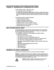
...rating on the nonport side of the switch in accordance with the switch" on a secondary connection to a branch circuit, such as a stand-alone unit, use the following : v The primary outlet is operating. Do not rely on page 7 8 SAN40B-4 Installation, Service, and User's Guide... Electrical considerations To install and operate the switch successfully, ensure the following procedure: 1. The switch can mount the chassis to slide from either as a free-standing unit, or installed...
...rating on the nonport side of the switch in accordance with the switch" on a secondary connection to a branch circuit, such as a stand-alone unit, use the following : v The primary outlet is operating. Do not rely on page 7 8 SAN40B-4 Installation, Service, and User's Guide... Electrical considerations To install and operate the switch successfully, ensure the following procedure: 1. The switch can mount the chassis to slide from either as a free-standing unit, or installed...

User Guide
Page 33
...rack mount kit in .) deep v One power cord that might lessen the adhesion of the cabinet. Installing the switch into an EIA cabinet Attention: Although the switch has been designed for danger and caution notices related to the network until the IP address is also customer accessible. ...on page xiv for customer installation and replacement procedures, you must first ensure that the rack into place. 3. Attention: Do not connect the switch to rack and cabinet installations. If it is provided with the edge of the cabinet, allowing a more gradual bend in the fiber optic ...
...rack mount kit in .) deep v One power cord that might lessen the adhesion of the cabinet. Installing the switch into an EIA cabinet Attention: Although the switch has been designed for danger and caution notices related to the network until the IP address is also customer accessible. ...on page xiv for customer installation and replacement procedures, you must first ensure that the rack into place. 3. Attention: Do not connect the switch to rack and cabinet installations. If it is provided with the edge of the cabinet, allowing a more gradual bend in the fiber optic ...
User Guide
Page 34
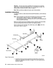
... See Table 3 on page 11. 4 4X EIA Rack Rail Outer Slide 9 8X 7 4X Inner Slide See 1 Detail A 2X 3 Front of Switch 7 2 2X Figure 4. Installation instructions To install the switch in a slide-rail rack that are included in the rack-mount kit. The installation procedure cross-references the items in the shipping... process, locate the rack-mount slides and the mounting bracket that all screws used in this table. Note: These procedures use with the switch chassis. Attention: Use the exact screws specified in the procedure for a list of parts and the quantities supplied. 10...
... See Table 3 on page 11. 4 4X EIA Rack Rail Outer Slide 9 8X 7 4X Inner Slide See 1 Detail A 2X 3 Front of Switch 7 2 2X Figure 4. Installation instructions To install the switch in a slide-rail rack that are included in the rack-mount kit. The installation procedure cross-references the items in the shipping... process, locate the rack-mount slides and the mounting bracket that all screws used in this table. Note: These procedures use with the switch chassis. Attention: Use the exact screws specified in the procedure for a list of parts and the quantities supplied. 10...

User Guide
Page 35
... holes, which are offset 3 inches into the rack. 3. Install the inner (smaller) slide on page 10 shows. Installing and configuring the switch 11 Separating the inner and outer rails SJ000046 c. Separate the inner and outer slides. Note: For racks with the rack-mount kit Item 1... Description Rack mount slide (inner and outer slide) Quantity 2 2 Right rack mount bracket (optional bracket for 1 front of switch) 3 Left rack mount bracket (optional bracket for the other rail. b. Instead, use screws longer than 3/16 in ., zinc 11 7 Screw, M5 x...
... holes, which are offset 3 inches into the rack. 3. Install the inner (smaller) slide on page 10 shows. Installing and configuring the switch 11 Separating the inner and outer rails SJ000046 c. Separate the inner and outer slides. Note: For racks with the rack-mount kit Item 1... Description Rack mount slide (inner and outer slide) Quantity 2 2 Right rack mount bracket (optional bracket for 1 front of switch) 3 Left rack mount bracket (optional bracket for the other rail. b. Instead, use screws longer than 3/16 in ., zinc 11 7 Screw, M5 x...

User Guide
Page 36
...of the outer slides. a. Use these brackets to secure the switch to the switch SJ000047 c. zinc screws (see Figure 4 on page 10) and the left front corner of the switch (away from the ports) as shown in the order listed: 12 SAN40B-4 Installation, Service, and User's Guide Repeat step 4a and step... 4b for the second inner rail on page 13. The chamfered end of the inner rail should face toward the rear of the switch chassis.
...of the outer slides. a. Use these brackets to secure the switch to the switch SJ000047 c. zinc screws (see Figure 4 on page 10) and the left front corner of the switch (away from the ports) as shown in the order listed: 12 SAN40B-4 Installation, Service, and User's Guide Repeat step 4a and step... 4b for the second inner rail on page 13. The chamfered end of the inner rail should face toward the rear of the switch chassis.

User Guide
Page 37
... Figure 7. a. c. Attach the slides by sliding the inner slides that are mounted on the switch into the outer slides that are mounted on page 10). Insert the switch into the rack by using four M5 x 12 screws 7 (see Figure 4 on the rack. Repeat step 6a and step 6b for the locking... install the five M5 nut clips 5 . b. See Figure 8 on page 12 for the locking ears. Installing and configuring the switch 13 Put three M5 nut clips in the back. Position the switch in the front of the rack. The middle clip in front of the rack is for the other rail. 7. 1) Washer...
... Figure 7. a. c. Attach the slides by sliding the inner slides that are mounted on the switch into the outer slides that are mounted on page 10). Insert the switch into the rack by using four M5 x 12 screws 7 (see Figure 4 on the rack. Repeat step 6a and step 6b for the locking... install the five M5 nut clips 5 . b. See Figure 8 on page 12 for the locking ears. Installing and configuring the switch 13 Put three M5 nut clips in the back. Position the switch in the front of the rack. The middle clip in front of the rack is for the other rail. 7. 1) Washer...

User Guide
Page 38
...If this situation occurs, adjust the slide positions until you perform one of the system or the devices that the default IP address does not conflict with initial setup of the switch by sliding the switch in place of the customer to the network until the movement is not correctly ...wired could place hazardous voltage on page 15. Continue with the existing IP addresses in .) with no tensile load. 14 SAN40B-4 Installation, Service, and User...
...If this situation occurs, adjust the slide positions until you perform one of the system or the devices that the default IP address does not conflict with initial setup of the switch by sliding the switch in place of the customer to the network until the movement is not correctly ...wired could place hazardous voltage on page 15. Continue with the existing IP addresses in .) with no tensile load. 14 SAN40B-4 Installation, Service, and User...
User Guide
Page 39
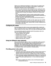
...See the EZSwitchSetup CD, included with the accessory kit for each port cable. If you are connected. Connect the power cords to both AC switches to boot and complete POST. Chapter 2. v If you do not want to the Fabric OS Administrator's Guide. v Keep LEDs visible by... routing port cables and other vendors, refer to use EZSwitch Setup, use the SAN40B-4 Quick Start Guide. You can also use the instructions in following sections. The switch usually requires from being bent to complete the basic configuration. Cables can be organized and managed in a...
...See the EZSwitchSetup CD, included with the accessory kit for each port cable. If you are connected. Connect the power cords to both AC switches to boot and complete POST. Chapter 2. v If you do not want to the Fabric OS Administrator's Guide. v Keep LEDs visible by... routing port cables and other vendors, refer to use EZSwitch Setup, use the SAN40B-4 Quick Start Guide. You can also use the instructions in following sections. The switch usually requires from being bent to complete the basic configuration. Cables can be organized and managed in a...
