User Guide
Page 5
... address 16 Setting the date and time 17 © Copyright IBM Corp. 2008 iii Installing and configuring the switch 7 Items included with the switch 7 Installation and safety considerations 7 Electrical considerations 8 Environment considerations 8 Cabinet considerations 8 Installing a stand-alone switch 8 Installing the switch into an EIA cabinet 9 Time required 9 Items required 9 Installation instructions 10 Recommendations for cable...
... address 16 Setting the date and time 17 © Copyright IBM Corp. 2008 iii Installing and configuring the switch 7 Items included with the switch 7 Installation and safety considerations 7 Electrical considerations 8 Environment considerations 8 Cabinet considerations 8 Installing a stand-alone switch 8 Installing the switch into an EIA cabinet 9 Time required 9 Items required 9 Installation instructions 10 Recommendations for cable...
User Guide
Page 6
...(CRUs/FRUs 31 Time required 32 Items required 32 Replacement instructions 32 Managing the switch 33 Appendix. Chapter 3. Product specifications 35 Weight and physical dimensions 35 Facility requirements...37 Data transmission ranges 37 Fibre Channel port specifications 38 Serial port specifications 38 Power supply specifications 38 Supported SFPs and HBAs 39 System specifications 39 Notices 41 Trademarks 43 Electronic emission notices 44 Federal Communications Commission (...Korea Class A Electronic Emission Statement 46 Index 47 iv SAN40B-4 Installation, Service, and User's Guide
...(CRUs/FRUs 31 Time required 32 Items required 32 Replacement instructions 32 Managing the switch 33 Appendix. Chapter 3. Product specifications 35 Weight and physical dimensions 35 Facility requirements...37 Data transmission ranges 37 Fibre Channel port specifications 38 Serial port specifications 38 Power supply specifications 38 Supported SFPs and HBAs 39 System specifications 39 Notices 41 Trademarks 43 Electronic emission notices 44 Federal Communications Commission (...Korea Class A Electronic Emission Statement 46 Index 47 iv SAN40B-4 Installation, Service, and User's Guide

User Guide
Page 7
Fibre Channel port numbering 3 3. Captive screws on the nonport side of the switch 22 11. Installing a replacement power supply fan assembly 33 © Copyright IBM Corp. 2008 v Figures 1. Separating the inner and outer rails 11 6. Rack assembly 10 5. Removing an SFP 29 13. Inserting slides into the rack rails 14 9. ...
Fibre Channel port numbering 3 3. Captive screws on the nonport side of the switch 22 11. Installing a replacement power supply fan assembly 33 © Copyright IBM Corp. 2008 v Figures 1. Separating the inner and outer rails 11 6. Rack assembly 10 5. Removing an SFP 29 13. Inserting slides into the rack rails 14 9. ...
User Guide
Page 9
... 12. Serial cable pinouts 38 16. General specifications 39 © Copyright IBM Corp. 2008 vii Power status LED patterns, status, and recommended actions 23 5. Management options for the switch 33 10. Physical dimensions and weight of the switch 35 11. Ethernet LED patterns 24 8. System status LED patterns, status, and recommended actions 23 6. Memory specifications...
... 12. Serial cable pinouts 38 16. General specifications 39 © Copyright IBM Corp. 2008 vii Power status LED patterns, status, and recommended actions 23 5. Management options for the switch 33 10. Physical dimensions and weight of the switch 35 11. Ethernet LED patterns 24 8. System status LED patterns, status, and recommended actions 23 6. Memory specifications...

User Guide
Page 12
... shock hazards when servicing equipment. If any of the system or the devices that is provided with your system electrical requirements do not touch the shell until you have... are corrected before proceeding. (D003) DANGER An electrical outlet that your device or the power rating label for electrical specifications. (D002) DANGER If the receptacle has a metal shell... protection requirements. Ensure the improper voltage or impedance conditions are not as described, STOP. x SAN40B-4 Installation, Service, and User's Guide DANGER Overloading a branch circuit is not correctly wired could...
... shock hazards when servicing equipment. If any of the system or the devices that is provided with your system electrical requirements do not touch the shell until you have... are corrected before proceeding. (D003) DANGER An electrical outlet that your device or the power rating label for electrical specifications. (D002) DANGER If the receptacle has a metal shell... protection requirements. Ensure the improper voltage or impedance conditions are not as described, STOP. x SAN40B-4 Installation, Service, and User's Guide DANGER Overloading a branch circuit is not correctly wired could...
User Guide
Page 13
... installation and configuration procedures. Turn off everything (unless instructed otherwise). 2. Remove all cables to the system rating plate. v When possible, use the IBM provided power cord for any power supply assembly. Turn off everything (unless instructed otherwise). 2. Attach the power cords to connect or disconnect signal cables. v Never turn on this product during an electrical...
... installation and configuration procedures. Turn off everything (unless instructed otherwise). 2. Remove all cables to the system rating plate. v When possible, use the IBM provided power cord for any power supply assembly. Turn off everything (unless instructed otherwise). 2. Attach the power cords to connect or disconnect signal cables. v Never turn on this product during an electrical...

User Guide
Page 14
...the use of the laser as defined by the classification of a laser in system outage and possible physical injury. Remove all metallic jewelry before installing or servicing ...smaller than electrical danger. A hazardous electrical condition with a 3-wire (two conductors and ground) power cable and plug. A hazardous condition due to avoid electrical shock. (C018) CAUTION: Servicing... symbols. A generally hazardous condition not represented by trained service personnel only. (C032) xii SAN40B-4 Installation, Service, and User's Guide A potential hazard of Health and Human Services (for...
...the use of the laser as defined by the classification of a laser in system outage and possible physical injury. Remove all metallic jewelry before installing or servicing ...smaller than electrical danger. A hazardous electrical condition with a 3-wire (two conductors and ground) power cable and plug. A hazardous condition due to avoid electrical shock. (C018) CAUTION: Servicing... symbols. A generally hazardous condition not represented by trained service personnel only. (C032) xii SAN40B-4 Installation, Service, and User's Guide A potential hazard of Health and Human Services (for...

User Guide
Page 15
...can cause severe injury or death. (L004) Attention notices An attention notice indicates the possibility of damage to a program, device, or system, or to data. An exclamation point symbol may differ from these sample safety labels: DANGER Hazardous voltage, current, or energy levels are... devices are often installed directly on products or product components to warn of the hazard. To remove all hazardous voltages, disconnect all power cords. (L003) DANGER Hazardous voltage present. Voltages present constitute a shock hazard, which can be either danger or caution notices, depending...
...can cause severe injury or death. (L004) Attention notices An attention notice indicates the possibility of damage to a program, device, or system, or to data. An exclamation point symbol may differ from these sample safety labels: DANGER Hazardous voltage, current, or energy levels are... devices are often installed directly on products or product components to warn of the hazard. To remove all hazardous voltages, disconnect all power cords. (L003) DANGER Hazardous voltage present. Voltages present constitute a shock hazard, which can be either danger or caution notices, depending...
User Guide
Page 16
... out or install any side, front, or back of the customer to ensure that attach to power devices installed in a rack cabinet to the system. Do not place objects on top of 2) xiv SAN40B-4 Installation, Service, and User's Guide v Each rack cabinet might cause the rack to become ...unstable if you pull out more than one drawer at a time. Do not pull out more than one power cord. It is compromised...
... out or install any side, front, or back of the customer to ensure that attach to power devices installed in a rack cabinet to the system. Do not place objects on top of 2) xiv SAN40B-4 Installation, Service, and User's Guide v Each rack cabinet might cause the rack to become ...unstable if you pull out more than one drawer at a time. Do not pull out more than one power cord. It is compromised...
User Guide
Page 25
...-configure as the SAN grows. Chapter 1. v Two hot-swappable, redundant integrated power supply and fan field replaceable units (FRUs). v Offers forward and backward compatibility with the optional Integrated Routing license. Introducing the SAN40B-4 switch The IBM System Storage SAN40B-4 is an enterprise-class 8 Gbps Fibre Channel switch that is scalable through additional port activation, you can use it...
...-configure as the SAN grows. Chapter 1. v Two hot-swappable, redundant integrated power supply and fan field replaceable units (FRUs). v Offers forward and backward compatibility with the optional Integrated Routing license. Introducing the SAN40B-4 switch The IBM System Storage SAN40B-4 is an enterprise-class 8 Gbps Fibre Channel switch that is scalable through additional port activation, you can use it...
User Guide
Page 26
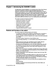
Hardware zoning is accomplished at the following web site: www.ibm.com/ servers/storage/support/san. v Small Form-Factor Pluggable (SFP) optical transceivers support any combination of the switch Item number 1 2 SAN40B-4 Installation, Service, and User's Guide 8 9 10 11 12 13 14 15 Description System status (top) and power (bottom) LEDs Port side of Short Wave (SW...
Hardware zoning is accomplished at the following web site: www.ibm.com/ servers/storage/support/san. v Small Form-Factor Pluggable (SFP) optical transceivers support any combination of the switch Item number 1 2 SAN40B-4 Installation, Service, and User's Guide 8 9 10 11 12 13 14 15 Description System status (top) and power (bottom) LEDs Port side of Short Wave (SW...

User Guide
Page 28
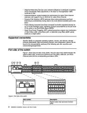
...As your needs increase, you with a key to be purchased with switch software, or you can purchase the license separately from IBM, who will provide you can be unlocked in Figure 3. The ...Power Supply/fan FRU 1) Power supply connector (for power supply/fan FRU 1) Fan (for power supply/fan FRU1) Field replaceable units (FRUs) The switch has two integrated power supply and fan assembly field replaceable units (FRUs). Figure 3 shows the non-port side items. 1 2 3 4 5 6 7 8 b40_0003 Figure 3. Each FRU has a status LED ( 2 and 6 in the switch firmware. After it . 4 SAN40B...
...As your needs increase, you with a key to be purchased with switch software, or you can purchase the license separately from IBM, who will provide you can be unlocked in Figure 3. The ...Power Supply/fan FRU 1) Power supply connector (for power supply/fan FRU 1) Fan (for power supply/fan FRU1) Field replaceable units (FRUs) The switch has two integrated power supply and fan assembly field replaceable units (FRUs). Figure 3 shows the non-port side items. 1 2 3 4 5 6 7 8 b40_0003 Figure 3. Each FRU has a status LED ( 2 and 6 in the switch firmware. After it . 4 SAN40B...
User Guide
Page 31
... following items are included in such a rack. One grounded 1.8 m (6 ft.) country-specific power cord - IBM System Storage SAN40B-4 Installation, Service, and User's Guide (this section to be installed is provided with an RJ-45 connector - IBM System Storage SAN40B-4 Quick Start Guide - Serial cable with the switch. Chapter 2. If it is not, then only trained personnel can mount the chassis...
... following items are included in such a rack. One grounded 1.8 m (6 ft.) country-specific power cord - IBM System Storage SAN40B-4 Installation, Service, and User's Guide (this section to be installed is provided with an RJ-45 connector - IBM System Storage SAN40B-4 Quick Start Guide - Serial cable with the switch. Chapter 2. If it is not, then only trained personnel can mount the chassis...

User Guide
Page 32
... the cabinet through a reliable branch circuit connection and maintain ground at all equipment in "Power supply specifications" on page 38 are met on page 7 8 SAN40B-4 Installation, Service, and User's Guide Environment considerations For successful installation and operation of the switch, ensure that the following cabinet requirements are adequate, as specified by a circuit breaker...
... the cabinet through a reliable branch circuit connection and maintain ground at all equipment in "Power supply specifications" on page 38 are met on page 7 8 SAN40B-4 Installation, Service, and User's Guide Environment considerations For successful installation and operation of the switch, ensure that the following cabinet requirements are adequate, as specified by a circuit breaker...

User Guide
Page 33
...environmental notices" on a flat, sturdy surface. 4. In this installation, the port side of the switch to the network until the IP address is to set 7.62 cm (3 in "Powering the switch on page xiv for customer installation and replacement procedures, you must first ensure that the rack into ...mount kit in such a rack. In this installation, the port side of the cabinet. a. b. Provide power to slide out the cool-air side of the switch is flush with the switch v One power outlet v Rack mount kit Chapter 2. v To allow the port side of the feet. Time required ...
...environmental notices" on a flat, sturdy surface. 4. In this installation, the port side of the switch to the network until the IP address is to set 7.62 cm (3 in "Powering the switch on page xiv for customer installation and replacement procedures, you must first ensure that the rack into ...mount kit in such a rack. In this installation, the port side of the cabinet. a. b. Provide power to slide out the cool-air side of the switch is flush with the switch v One power outlet v Rack mount kit Chapter 2. v To allow the port side of the feet. Time required ...
User Guide
Page 39
... with the accessory kit for more information about how to configure the switch to operate in a fabric that the cords have set up the switch in .) available and are connected. Power on . Note: Power is time to avoid stress. 2. Do not use the SAN40B-4 Quick Start Guide. For more information. v "Using the EZSwitch setup (optional...
... with the accessory kit for more information about how to configure the switch to operate in a fabric that the cords have set up the switch in .) available and are connected. Power on . Note: Power is time to avoid stress. 2. Do not use the SAN40B-4 Quick Start Guide. For more information. v "Using the EZSwitch setup (optional...
User Guide
Page 40
.... Ethernet IP Address: [192.168.74.102] If you are green. switch:admin> ipaddrset -ipv6 --add 1080::8:800:200C:417A/64 IP address is enabled by default. DHCP is being changed...Done. 16 SAN40B-4 Installation, Service, and User's Guide Connect the serial cable to the serial... port on the switch and to the a DHCP server that the switch power and status LEDs on the workstation. Disable any serial communication programs ...
.... Ethernet IP Address: [192.168.74.102] If you are green. switch:admin> ipaddrset -ipv6 --add 1080::8:800:200C:417A/64 IP address is enabled by default. DHCP is being changed...Done. 16 SAN40B-4 Installation, Service, and User's Guide Connect the serial cable to the serial... port on the switch and to the a DHCP server that the switch power and status LEDs on the workstation. Disable any serial communication programs ...
User Guide
Page 45
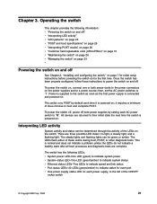
...it requires a minimum of the ON/OFF rocker switch © Copyright IBM Corp. 2008 21 To power the switch off, power off . This is powered on for each power supply, to the switch as soon as the first power supply is powered on the switch. The LEDs flash either of the LEDs on... lights and flashing lights can be green or amber. Operating the switch This chapter provides the following LEDs: v System power LED-One LED (green) to indicate system power v System status LED-One LED (green/amber) to indicate system status v Ethernet status LEDs-Two LEDs to indicate speed and link...
...it requires a minimum of the ON/OFF rocker switch © Copyright IBM Corp. 2008 21 To power the switch off, power off . This is powered on for each power supply, to the switch as soon as the first power supply is powered on the switch. The LEDs flash either of the LEDs on... lights and flashing lights can be green or amber. Operating the switch This chapter provides the following LEDs: v System power LED-One LED (green) to indicate system power v System status LED-One LED (green/amber) to indicate system status v Ethernet status LEDs-Two LEDs to indicate speed and link...

User Guide
Page 46
... the switch Item 1 2 3 LED names and descriptions System status LED (top) and System power (bottom) Ethernet link status (left LED provides status of the port in the top row, the right LED provides status of the port in the bottom row. Detailed view, location of LEDs on the nonport side of the switch 22 SAN40B-4 Installation...
... the switch Item 1 2 3 LED names and descriptions System status LED (top) and System power (bottom) Ethernet link status (left LED provides status of the port in the top row, the right LED provides status of the port in the bottom row. Detailed view, location of LEDs on the nonport side of the switch 22 SAN40B-4 Installation...

User Guide
Page 47
..., the unit is on the cause of hardware action Power Status LED No light System is off , boot is Verify that switch is faulty. completed booting. Verify the system is faulty. Steady green System is on and No action is on and has failed. Reboot the system. Contact IBM or more than five seconds) Boot failed, the...
..., the unit is on the cause of hardware action Power Status LED No light System is off , boot is Verify that switch is faulty. completed booting. Verify the system is faulty. Steady green System is on and No action is on and has failed. Reboot the system. Contact IBM or more than five seconds) Boot failed, the...
