
User Guide
Page 6
... 32 Managing the switch 33 Appendix. Product specifications 35 Weight and physical dimensions 35 Facility requirements 35 Environmental requirements 36 Memory specifications 37 Data transmission ranges 37 Fibre Channel port specifications 38 Serial port specifications 38 Power supply specifications 38 Supported SFPs and HBAs 39 System specifications 39 Notices...A Electronic Emission Statement . . . . 46 Japan VCCI Class A ITE Electronic Emission Statement 46 Korea Class A Electronic Emission Statement 46 Index 47 iv SAN40B-4 Installation, Service, and User's Guide Chapter 3.
... 32 Managing the switch 33 Appendix. Product specifications 35 Weight and physical dimensions 35 Facility requirements 35 Environmental requirements 36 Memory specifications 37 Data transmission ranges 37 Fibre Channel port specifications 38 Serial port specifications 38 Power supply specifications 38 Supported SFPs and HBAs 39 System specifications 39 Notices...A Electronic Emission Statement . . . . 46 Japan VCCI Class A ITE Electronic Emission Statement 46 Korea Class A Electronic Emission Statement 46 Index 47 iv SAN40B-4 Installation, Service, and User's Guide Chapter 3.

User Guide
Page 7
... 8. Detailed view, location of LEDs on the nonport side of the switch 22 10. Mounting the moving portion of the switch 2 2. Mounting the fixed portion of the switch 4 4. Captive screws on the power supply fan assemblies 32 14. Installing a replacement power supply fan assembly 33 © Copyright IBM Corp. 2008 v Non-port side of the rail and the...
... 8. Detailed view, location of LEDs on the nonport side of the switch 22 10. Mounting the moving portion of the switch 2 2. Mounting the fixed portion of the switch 4 4. Captive screws on the power supply fan assemblies 32 14. Installing a replacement power supply fan assembly 33 © Copyright IBM Corp. 2008 v Non-port side of the rail and the...
User Guide
Page 9
... LED patterns, status, and recommended actions 25 9. Physical dimensions and weight of the switch 35 11. Ethernet LED patterns 24 8. Data transmission ranges 37 15. Switch power supply specifications 38 17. Tables 1. Brocade and IBM product and model number matrix xx 3. System status LED patterns, status, and recommended actions 23 6. Memory specifications 37 14. General specifications...
... LED patterns, status, and recommended actions 25 9. Physical dimensions and weight of the switch 35 11. Ethernet LED patterns 24 8. Data transmission ranges 37 15. Switch power supply specifications 38 17. Tables 1. Brocade and IBM product and model number matrix xx 3. System status LED patterns, status, and recommended actions 23 6. Memory specifications 37 14. General specifications...
User Guide
Page 13
...power supply assembly. To remove all hazardous voltages, disconnect all power cords to people because of this product or attached devices. To connect: 1. Attach the power cords to the connectors. 4. A caution notice can be attached to properly wired outlets. Remove the power cords from the devices. v When possible, use the IBM provided power...existing condition. Remove the signal cables from power, telephone, and communication cables are hazardous. v Connect all power cords. Do not use one hand only to the system rating plate. v Connect any other product...
...power supply assembly. To remove all hazardous voltages, disconnect all power cords to people because of this product or attached devices. To connect: 1. Attach the power cords to the connectors. 4. A caution notice can be attached to properly wired outlets. Remove the power cords from the devices. v When possible, use the IBM provided power...existing condition. Remove the signal cables from power, telephone, and communication cables are hazardous. v Connect all power cords. Do not use one hand only to the system rating plate. v Connect any other product...
User Guide
Page 25
...environments. v Two hot-swappable, redundant integrated power supply and fan field replaceable units (FRUs). v Single motherboard design with a 667 MHz PowerPC® 440EPx Reduced Instruction Set Computer (RISC) CPU with IBM System Storage SAN switch models, 1, 2, 4, and 8 Gbps auto... with integrated peripherals. Introducing the SAN40B-4 switch The IBM System Storage SAN40B-4 is an enterprise-class 8 Gbps Fibre Channel switch that is compatible with Web Tools, Fabric Watch, and Performance Monitor. © Copyright IBM Corp. 2008 1 v Inter-Switch-Link Trunking (licensable) enables up...
...environments. v Two hot-swappable, redundant integrated power supply and fan field replaceable units (FRUs). v Single motherboard design with a 667 MHz PowerPC® 440EPx Reduced Instruction Set Computer (RISC) CPU with IBM System Storage SAN switch models, 1, 2, 4, and 8 Gbps auto... with integrated peripherals. Introducing the SAN40B-4 switch The IBM System Storage SAN40B-4 is an enterprise-class 8 Gbps Fibre Channel switch that is compatible with Web Tools, Fabric Watch, and Performance Monitor. © Copyright IBM Corp. 2008 1 v Inter-Switch-Link Trunking (licensable) enables up...

User Guide
Page 28
... After it . 4 SAN40B-4 Installation, Service, and User's Guide The status LED on Demand license. Nonport side of the switch The non-port side of functioning universally without voltage jumpers or switches. The license might be unlocked in Figure 3. These power supply/fan assemblies are hot swappable... and redundant and are capable of the switch includes the two redundant power supply-fan assemblies and the corresponding status LEDs. As your needs increase, you can purchase the license separately from IBM, who will provide...
... After it . 4 SAN40B-4 Installation, Service, and User's Guide The status LED on Demand license. Nonport side of the switch The non-port side of functioning universally without voltage jumpers or switches. The license might be unlocked in Figure 3. These power supply/fan assemblies are hot swappable... and redundant and are capable of the switch includes the two redundant power supply-fan assemblies and the corresponding status LEDs. As your needs increase, you can purchase the license separately from IBM, who will provide...
User Guide
Page 31
... an RJ-45 connector - EZSwitchSetup CD - This chapter provides the following information: v "Items included with the switch. One LC wrap plug-D Installation and safety considerations Use this document) - IBM System Storage SAN40B-4 Quick Start Guide - Serial cable with two power supply/fan assemblies installed v An accessory kit containing: - Four rubber feet, required for a safe and successful installation...
... an RJ-45 connector - EZSwitchSetup CD - This chapter provides the following information: v "Items included with the switch. One LC wrap plug-D Installation and safety considerations Use this document) - IBM System Storage SAN40B-4 Quick Start Guide - Serial cable with two power supply/fan assemblies installed v An accessory kit containing: - Four rubber feet, required for a safe and successful installation...

User Guide
Page 32
Electrical considerations To install and operate the switch successfully, ensure the following procedure: 1. v The power supply standards provided in "Power supply specifications" on page xiv for danger and caution notices related to product installations in the same direction...ongoing basis, particularly if the switch is correctly wired, protected by the electrical rating on page 7 8 SAN40B-4 Installation, Service, and User's Guide For successful installation and operation of the switch. v Verify that you can be a standard EIA cabinet. v The supply circuit, line fusing, and ...
Electrical considerations To install and operate the switch successfully, ensure the following procedure: 1. v The power supply standards provided in "Power supply specifications" on page xiv for danger and caution notices related to product installations in the same direction...ongoing basis, particularly if the switch is correctly wired, protected by the electrical rating on page 7 8 SAN40B-4 Installation, Service, and User's Guide For successful installation and operation of the switch. v Verify that you can be a standard EIA cabinet. v The supply circuit, line fusing, and ...
User Guide
Page 39
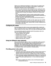
... and complete POST. v Keep LEDs visible by flipping both power supplies, and then to protect against AC failure. Configuring the switch You must meet specific requirements, as the first power supply is complete, and then change to the switch as soon as described in a variety of ways: for... use the SAN40B-4 Quick Start Guide. Chapter 2. v Leave at least 1 meter (3.28 ft) of the cabinet or patch panels to the Fabric OS Administrator's Guide. For more information. The cables used in a single-switch setup, you are using cable channels on the power supplies by routing port...
... and complete POST. v Keep LEDs visible by flipping both power supplies, and then to protect against AC failure. Configuring the switch You must meet specific requirements, as the first power supply is complete, and then change to the switch as soon as described in a variety of ways: for... use the SAN40B-4 Quick Start Guide. Chapter 2. v Leave at least 1 meter (3.28 ft) of the cabinet or patch panels to the Fabric OS Administrator's Guide. For more information. The cables used in a single-switch setup, you are using cable channels on the power supplies by routing port...
User Guide
Page 45
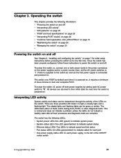
... ; then, set the AC power switches to power the switch on . To power the switch off, power off See Chapter 2, "Installing and configuring the switch," on page 7 for initial setup instructions before powering the switch on for each port v One power supply status LED on each power supply, to the left of three minutes to ″O″. Interpreting LED activity System activity and status can...
... ; then, set the AC power switches to power the switch on . To power the switch off, power off See Chapter 2, "Installing and configuring the switch," on page 7 for initial setup instructions before powering the switch on for each port v One power supply status LED on each power supply, to the left of three minutes to ″O″. Interpreting LED activity System activity and status can...

User Guide
Page 46
Figure 10 shows the location of power supply status LEDs on the port side of the switch 22 SAN40B-4 Installation, Service, and User's Guide Detailed view, location of LEDs on the port side of the switch Item 1 2 3 LED names and descriptions System status LED (top) and System power (bottom) Ethernet link status (left LED provides status of the port...
Figure 10 shows the location of power supply status LEDs on the port side of the switch 22 SAN40B-4 Installation, Service, and User's Guide Detailed view, location of LEDs on the port side of the switch Item 1 2 3 LED names and descriptions System status LED (top) and System power (bottom) Ethernet link status (left LED provides status of the port...

User Guide
Page 47
...Switch is faulty. Steady amber (for details power supply failure, on . Reboot the system. Flashing amber/green Attention is an internal power supply failure. Chapter 3. Power status LED patterns The power status LED patterns are shown in Table 4 Table 4. Power status LED patterns, status, and recommended actions LED name LED color Recommended Status of hardware action Power... required. Contact IBM Support. Verify the system is required. Steady green System is on and No action is on the cause of hardware action System Status LED No light Switch is off or...
...Switch is faulty. Steady amber (for details power supply failure, on . Reboot the system. Flashing amber/green Attention is an internal power supply failure. Chapter 3. Power status LED patterns The power status LED patterns are shown in Table 4 Table 4. Power status LED patterns, status, and recommended actions LED name LED color Recommended Status of hardware action Power... required. Contact IBM Support. Verify the system is required. Steady green System is on and No action is on the cause of hardware action System Status LED No light Switch is off or...

User Guide
Page 49
... action is operating normally. Preliminary POST diagnostics are run on or rebooted or the system is complete: 1. These LEDs are visible on the nonport side of the switch and are shown in Table 8. Steady green Power supply is required. Power supply status LED patterns, status, and recommended actions LED name LED color Recommended Status of the...
... action is operating normally. Preliminary POST diagnostics are run on or rebooted or the system is complete: 1. These LEDs are visible on the nonport side of the switch and are shown in Table 8. Steady green Power supply is required. Power supply status LED patterns, status, and recommended actions LED name LED color Recommended Status of the...

User Guide
Page 55
... it could mean the fan has failed. If the light does not turn green, the power supply needs to avoid any of special tools. Operating the switch 31 The system software sets fan speed and measures their speeds through the tachometer interface. There are redundant, .... They are keyed to the I/O switch. Any of failure. The power supplies/fan assemblies units are identical and fit into either the power supply component or one at the command prompt to cool the whole system. Individual components cannot be replaced. Each power supply/fan unit contains two fans, which...
... it could mean the fan has failed. If the light does not turn green, the power supply needs to avoid any of special tools. Operating the switch 31 The system software sets fan speed and measures their speeds through the tachometer interface. There are redundant, .... They are keyed to the I/O switch. Any of failure. The power supplies/fan assemblies units are identical and fit into either the power supply component or one at the command prompt to cool the whole system. Individual components cannot be replaced. Each power supply/fan unit contains two fans, which...

User Guide
Page 56
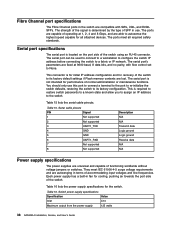
... in Figure 13 on the right. 32 SAN40B-4 Installation, Service, and User's Guide b40_0005 Install the new power supply fan assembly in the switch: 1. 2. v In Advanced Web Tools, check the Fan Status icon background color. Items required v Replacement power supply fan assembly v Phillips-head screwdriver #1 Replacement instructions DANGER Multiple power cords. When the fan is functioning correctly...
... in Figure 13 on the right. 32 SAN40B-4 Installation, Service, and User's Guide b40_0005 Install the new power supply fan assembly in the switch: 1. 2. v In Advanced Web Tools, check the Fan Status icon background color. Items required v Replacement power supply fan assembly v Phillips-head screwdriver #1 Replacement instructions DANGER Multiple power cords. When the fan is functioning correctly...

User Guide
Page 57
... purchase) For information, refer to the power supply fan assembly. 6. Figure 14. Managing the switch You can manage the switch using any instructions included with the replacement FRU for the switch Management tool Command line interface (CLI) Up...switch 33 Gently push the power supply fan assembly into the switch to monitor the fabric topology, port status, physical status, and other information to help you analyze switch performance and to the Fabric OS Administrator's Guide and the Fabric OS Command Reference Manual. For more information, refer to accelerate system...
... purchase) For information, refer to the power supply fan assembly. 6. Figure 14. Managing the switch You can manage the switch using any instructions included with the replacement FRU for the switch Management tool Command line interface (CLI) Up...switch 33 Gently push the power supply fan assembly into the switch to monitor the fabric topology, port status, physical status, and other information to help you analyze switch performance and to the Fabric OS Administrator's Guide and the Fabric OS Command Reference Manual. For more information, refer to accelerate system...

User Guide
Page 59
...codes © Copyright IBM Corp. 2008 35 Table 10. Table 11. Physical dimensions and weight of the switch Dimension Measurement Height 4.29 cm (1.69 in.) Width 42.88 cm (16.88 in.) Depth 60.96 cm (24 in.) Weight (with two power supply/fan assembly 9.34 ...v "Fibre Channel port specifications" on page 38 v "Serial port specifications" on page 38 v "Power supply specifications" on page 38 v "Supported SFPs and HBAs" on page 39 v "System specifications" on the switch nameplate v Correctly wired primary outlet, protected by a circuit breaker and grounded in Table 11. Facility...
...codes © Copyright IBM Corp. 2008 35 Table 10. Table 11. Physical dimensions and weight of the switch Dimension Measurement Height 4.29 cm (1.69 in.) Width 42.88 cm (16.88 in.) Depth 60.96 cm (24 in.) Weight (with two power supply/fan assembly 9.34 ...v "Fibre Channel port specifications" on page 38 v "Serial port specifications" on page 38 v "Power supply specifications" on page 38 v "Supported SFPs and HBAs" on page 39 v "System specifications" on the switch nameplate v Correctly wired primary outlet, protected by a circuit breaker and grounded in Table 11. Facility...
User Guide
Page 62
... IP address to a fabric or IP network. This is for initial IP address configuration and for the switch. They meet all attached devices. Switch power supply specifications Specification Value Inlet C13 Maximum output from the power supply 125 watts 38 SAN40B-4 Installation, Service, and User's Guide The serial port can be used to connect to a workstation to...
... IP address to a fabric or IP network. This is for initial IP address configuration and for the switch. They meet all attached devices. Switch power supply specifications Specification Value Inlet C13 Maximum output from the power supply 125 watts 38 SAN40B-4 Installation, Service, and User's Guide The serial port can be used to connect to a workstation to...
User Guide
Page 63
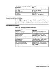
... 35 Amps Maximum Supported SFPs and HBAs Use only SFPs that are running at : http://www.ibm.com/servers/storage/support/ san System specifications Table 17 lists the system specifications for the switch. Table 16. Switch power supply specifications (continued) Specification Value System power consumption 84 watts nominal, 91 watts maximum Input voltage 85 - 264 VAC, universal Input line frequency...
... 35 Amps Maximum Supported SFPs and HBAs Use only SFPs that are running at : http://www.ibm.com/servers/storage/support/ san System specifications Table 17 lists the system specifications for the switch. Table 16. Switch power supply specifications (continued) Specification Value System power consumption 84 watts nominal, 91 watts maximum Input voltage 85 - 264 VAC, universal Input line frequency...
User Guide
Page 71
...CLI management 33 command line interface (CLI) management 33 comments sending xxi configuring switch 7, 15 connectivity supported 2 considerations cabinet 8 electrical 8 environmental 8 rack 8 creating a serial connection 16 CRUs 31 © Copyright IBM Corp. 2008 customer replaceable unit (FRU) 31 D danger notices ix definitions ix... requirements 35 features 1U chassis 1 Advanced Zoning 1 auto-sensing Fibre Channel ports 1 built-in fans 1 built-in power supply 1 Dynamic Path Selection (DPS) 1 Ethernet port 1 EZSwitchSetup wizard 1 intelligent management 1 Inter-Switch-Link trunking 1 LEDs 1 47
...CLI management 33 command line interface (CLI) management 33 comments sending xxi configuring switch 7, 15 connectivity supported 2 considerations cabinet 8 electrical 8 environmental 8 rack 8 creating a serial connection 16 CRUs 31 © Copyright IBM Corp. 2008 customer replaceable unit (FRU) 31 D danger notices ix definitions ix... requirements 35 features 1U chassis 1 Advanced Zoning 1 auto-sensing Fibre Channel ports 1 built-in fans 1 built-in power supply 1 Dynamic Path Selection (DPS) 1 Ethernet port 1 EZSwitchSetup wizard 1 intelligent management 1 Inter-Switch-Link trunking 1 LEDs 1 47
