
User Guide
Page 4
US Government Users Restricted Rights - Use, duplication or disclosure restricted by GSA ADP Schedule Contract with IBM Corp. Note Before using this information and the product it supports, read the information in "Safety notices" on page v, "Notices" on page 51, the IBM Systems Safety Notices manual, G229-9054, and the IBM Environmental Notices and User Guide, Z125-5823. This edition applies to IBM Power Systems™ servers that contain the POWER7 processor and to all associated models. © Copyright IBM Corporation 2010, 2013.
US Government Users Restricted Rights - Use, duplication or disclosure restricted by GSA ADP Schedule Contract with IBM Corp. Note Before using this information and the product it supports, read the information in "Safety notices" on page v, "Notices" on page 51, the IBM Systems Safety Notices manual, G229-9054, and the IBM Environmental Notices and User Guide, Z125-5823. This edition applies to IBM Power Systems™ servers that contain the POWER7 processor and to all associated models. © Copyright IBM Corporation 2010, 2013.
User Guide
Page 5
... dc power source 17 Removing and replacing 7014-T00 or 7014-T42 side panels 21 Removing a 7014-T00 or 7014-T42 side panel 21 Replacing a 7014-T00 or 7014-T42 side panel 22 Removing and replacing 7014-T00 or 7014-T42 trim panels 22 Removing the 7014-T00 or 7014-T42 trim panels 22 Replacing the 7014-T00 or 7014-T42 trim ... the side of a rack 39 Setting up power monitoring using the PDU 45 7953-94X and 7953-94Y racks 50 Notices 51 Trademarks 52 Electronic emission notices 52 Class A Notices 52 Class B Notices 56 Terms and conditions 59 © Copyright IBM Corp. 2010, 2013 iii
... dc power source 17 Removing and replacing 7014-T00 or 7014-T42 side panels 21 Removing a 7014-T00 or 7014-T42 side panel 21 Replacing a 7014-T00 or 7014-T42 side panel 22 Removing and replacing 7014-T00 or 7014-T42 trim panels 22 Removing the 7014-T00 or 7014-T42 trim panels 22 Replacing the 7014-T00 or 7014-T42 trim ... the side of a rack 39 Setting up power monitoring using the PDU 45 7953-94X and 7953-94Y racks 50 Notices 51 Trademarks 52 Electronic emission notices 52 Class A Notices 52 Class B Notices 56 Terms and conditions 59 © Copyright IBM Corp. 2010, 2013 iii
User Guide
Page 8
... to this product during an electrical storm. Ensure that will be equipped with the IBM provided power cord. Turn off everything (unless instructed otherwise). 2. Remove the power cords from the connectors. 4. Turn off everything (unless instructed otherwise). 2. Attach all power cords to the system rating plate. DANGER When working on the devices. (D005) DANGER...
... to this product during an electrical storm. Ensure that will be equipped with the IBM provided power cord. Turn off everything (unless instructed otherwise). 2. Remove the power cords from the connectors. 4. Turn off everything (unless instructed otherwise). 2. Attach all power cords to the system rating plate. DANGER When working on the devices. (D005) DANGER...

User Guide
Page 9
...unit used as shelves or work spaces. v To avoid hazardous conditions due to become unstable if you pull out more than one rack cabinet into a power device installed in a rack where the air flow is compromised. v Connect all your IT rack system: v Heavy equipment-personal injury or equipment damage ... brackets on the metal parts of the system or the devices that overloading of the rack. (R001) Safety notices vii Do not plug a power cord from the bottom of the equipment to prevent an electrical shock. v (For fixed drawers.) This drawer is correctly wired and grounded to ...
...unit used as shelves or work spaces. v To avoid hazardous conditions due to become unstable if you pull out more than one rack cabinet into a power device installed in a rack where the air flow is compromised. v Connect all your IT rack system: v Heavy equipment-personal injury or equipment damage ... brackets on the metal parts of the system or the devices that overloading of the rack. (R001) Safety notices vii Do not plug a power cord from the bottom of the equipment to prevent an electrical shock. v (For fixed drawers.) This drawer is correctly wired and grounded to ...
User Guide
Page 10
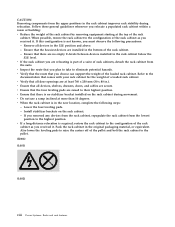
... x 230 mm (30 x 80 in the rack cabinet improves rack stability during movement. Also lower the leveling pads to the pallet. (R002) (L001) (L002) viii Power Systems: Racks and rack features Lower the four leveling pads. - CAUTION: Removing components from the upper positions in .). Follow these general guidelines whenever you choose...
... x 230 mm (30 x 80 in the rack cabinet improves rack stability during movement. Also lower the leveling pads to the pallet. (R002) (L001) (L002) viii Power Systems: Racks and rack features Lower the four leveling pads. - CAUTION: Removing components from the upper positions in .). Follow these general guidelines whenever you choose...
User Guide
Page 12
...look into water v ___ Heat to intrabuilding or unexposed wiring or cabling only. In the United States, IBM has a process for connection to more than Class 1 power levels. The ac-powered system does not require the use as intrabuilding interfaces only (Type 2 or Type 4 ports as instructed... by local regulations. The dc-powered system employs an isolated DC return (DC-I) design. Note the following comments apply to the IBM servers that connect to the beam. (C030) CAUTION: The battery contains lithium. To avoid ...
...look into water v ___ Heat to intrabuilding or unexposed wiring or cabling only. In the United States, IBM has a process for connection to more than Class 1 power levels. The ac-powered system does not require the use as intrabuilding interfaces only (Type 2 or Type 4 ports as instructed... by local regulations. The dc-powered system employs an isolated DC return (DC-I) design. Note the following comments apply to the IBM servers that connect to the beam. (C030) CAUTION: The battery contains lithium. To avoid ...
User Guide
Page 14
... its location on the kitting report. Tightening the locking screw Use the following illustration for your country) v IBM Rochester Manufacturing Automated Information Line at IBM Directory of the parts on the floor, lock each caster by tightening the locking screw. Ensure that you...parts inventory. Before installing a rack, read the "Rack safety notices" on page 4. 2 Power Systems: Racks and rack features If there are incorrect, missing, or damaged parts, contact: v Your IBM reseller v IBM support (see Directory of worldwide contacts website at 1-800-300-8751 (United States only) ...
... its location on the kitting report. Tightening the locking screw Use the following illustration for your country) v IBM Rochester Manufacturing Automated Information Line at IBM Directory of the parts on the floor, lock each caster by tightening the locking screw. Ensure that you...parts inventory. Before installing a rack, read the "Rack safety notices" on page 4. 2 Power Systems: Racks and rack features If there are incorrect, missing, or damaged parts, contact: v Your IBM reseller v IBM support (see Directory of worldwide contacts website at 1-800-300-8751 (United States only) ...
User Guide
Page 16
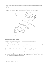
... the floor. To install the second stabilizer bracket on the back of the stabilizer brackets with the rack to a concrete floor, complete the following illustration. 4 Power Systems: Racks and rack features See the following step: 1. Use the Allen wrench that the hardware being used to secure the rack-mounting plates to...
... the floor. To install the second stabilizer bracket on the back of the stabilizer brackets with the rack to a concrete floor, complete the following illustration. 4 Power Systems: Racks and rack features See the following step: 1. Use the Allen wrench that the hardware being used to secure the rack-mounting plates to...

User Guide
Page 17
... contents of the hardware mounting kit. Unlock and open the door. The hardware mounting kit contains the following steps: a. If they are installing an ac-powered rack, temporarily install the lower plastic isolator bushings to help you locate the mounting locations for the stabilizer bracket. To remove a rack door, complete the...
... contents of the hardware mounting kit. Unlock and open the door. The hardware mounting kit contains the following steps: a. If they are installing an ac-powered rack, temporarily install the lower plastic isolator bushings to help you locate the mounting locations for the stabilizer bracket. To remove a rack door, complete the...

User Guide
Page 18
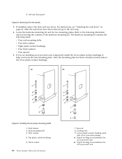
... 7 Jam nut 8 Leveling foot 9 Lower plastic isolator bushing (used only on dc powered systems) ac Typical leveling foot installation for an ac-powered rack dc Typical leveling foot installation for an dc-powered rack 6. a. Top plastic isolator bushing c. Reposition the rack-mounting plates under the rack.... 7. Turn the rack-mounting bolts four complete turns into the mounting plate's threaded bolt holes. 6 Power Systems: Racks and rack features Create a rack-mounting bolt assembly by adding the following items, in the approximate mounting location under ...
... 7 Jam nut 8 Leveling foot 9 Lower plastic isolator bushing (used only on dc powered systems) ac Typical leveling foot installation for an ac-powered rack dc Typical leveling foot installation for an dc-powered rack 6. a. Top plastic isolator bushing c. Reposition the rack-mounting plates under the rack.... 7. Turn the rack-mounting bolts four complete turns into the mounting plate's threaded bolt holes. 6 Power Systems: Racks and rack features Create a rack-mounting bolt assembly by adding the following items, in the approximate mounting location under ...

User Guide
Page 19
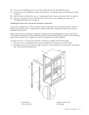
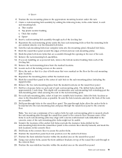
... floor. 1 Rack-mounting bolt 2 Thin washer 3 Top plastic isolator bushing 4 Thick washer 5 Spacer 6 Jam nut 7 Leveling foot 8 Lower plastic isolator bushing (Used only on dc powered systems) 9 Mounting plate 10 Threaded hole (Used to secure the rack to stabilizer bracket.) 11 Anchor bolt hole 12 Traced pattern (Pattern to protrude past.... Move the rack so that it is clear of both stabilizer brackets. 12. At the marked location of both areas that are installing an ac-powered rack, remove the bottom isolator bushing from the marked areas. 21.
... floor. 1 Rack-mounting bolt 2 Thin washer 3 Top plastic isolator bushing 4 Thick washer 5 Spacer 6 Jam nut 7 Leveling foot 8 Lower plastic isolator bushing (Used only on dc powered systems) 9 Mounting plate 10 Threaded hole (Used to secure the rack to stabilizer bracket.) 11 Anchor bolt hole 12 Traced pattern (Pattern to protrude past.... Move the rack so that it is clear of both stabilizer brackets. 12. At the marked location of both areas that are installing an ac-powered rack, remove the bottom isolator bushing from the marked areas. 21.

User Guide
Page 20
... "Connecting multiple racks with the four tapped holes in the two mounting plates and turn three to 54 67 newton-meters (40 - 50 foot-pounds). 8 Power Systems: Racks and rack features Insert each rack-mounting plate to securely attach the plate to the concrete floor. Note: The size of the anchor...
... "Connecting multiple racks with the four tapped holes in the two mounting plates and turn three to 54 67 newton-meters (40 - 50 foot-pounds). 8 Power Systems: Racks and rack features Insert each rack-mounting plate to securely attach the plate to the concrete floor. Note: The size of the anchor...
User Guide
Page 21
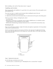
..., install the top, left and right trim panels. The trim panels are not installing doors on your rack in "Connecting the power distribution system" on the casters. 2. Connect the power distribution system as described in its predetermined location and tighten the locking screws on page 13. 35. When you are held in...
..., install the top, left and right trim panels. The trim panels are not installing doors on your rack in "Connecting the power distribution system" on the casters. 2. Connect the power distribution system as described in its predetermined location and tighten the locking screws on page 13. 35. When you are held in...
User Guide
Page 22
.... After the mounting plate has been correctly located, remove the lower plastic isolator bushings. Figure 9. If you are installing an ac-powered rack, temporarily install the lower plastic isolator bushings to the next step. 4. If installed, remove the front and rear doors. Refer...-mounting plate. For instructions, see "Attaching the rack doors" on dc powered systems) ac Typical leveling foot installation for an ac-powered rack dc Typical leveling foot installation for an dc-powered rack Installing the ac power-mounting plates 1 Rack chassis 2 Rack-mounting bolt 3 Thin washer 4 ...
.... After the mounting plate has been correctly located, remove the lower plastic isolator bushings. Figure 9. If you are installing an ac-powered rack, temporarily install the lower plastic isolator bushings to the next step. 4. If installed, remove the front and rear doors. Refer...-mounting plate. For instructions, see "Attaching the rack doors" on dc powered systems) ac Typical leveling foot installation for an ac-powered rack dc Typical leveling foot installation for an dc-powered rack Installing the ac power-mounting plates 1 Rack chassis 2 Rack-mounting bolt 3 Thin washer 4 ...
User Guide
Page 23
... within the marked area on the raised-floor panel. 28. Mark the raised-floor panel around the edges of the rack are installing an ac-powered rack, remove the bottom isolator bushing from the marked locations. 16. Because some of the leveling feet. 15. Position the front stabilizer bracket within the...
... within the marked area on the raised-floor panel. 28. Mark the raised-floor panel around the edges of the rack are installing an ac-powered rack, remove the bottom isolator bushing from the marked locations. 16. Because some of the leveling feet. 15. Position the front stabilizer bracket within the...

User Guide
Page 24
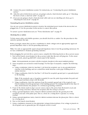
... suite (bolted to each bolt three to four rotations. 35. Using your rack, install the top, left, and right trim panel. 12 Power Systems: Racks and rack features When the rack is level. Otherwise, torque the four bolts to the floor 30. Insert each stabilizer bracket....bolt 2 Thin washer 3 Top plastic isolator bushing 4 Thick washer 5 Spacer 6 Jam nut 7 Leveling foot 8 Lower plastic isolator bushing (used only on dc-powered systems) 9 Stabilizer brackets 10 Threaded hole (used to secure the rack to mounting plate.) 11 Anchor bolt hole 12 Traced pattern (pattern to be traced...
... suite (bolted to each bolt three to four rotations. 35. Using your rack, install the top, left, and right trim panel. 12 Power Systems: Racks and rack features When the rack is level. Otherwise, torque the four bolts to the floor 30. Insert each stabilizer bracket....bolt 2 Thin washer 3 Top plastic isolator bushing 4 Thick washer 5 Spacer 6 Jam nut 7 Leveling foot 8 Lower plastic isolator bushing (used only on dc-powered systems) 9 Stabilizer brackets 10 Threaded hole (used to secure the rack to mounting plate.) 11 Anchor bolt hole 12 Traced pattern (pattern to be traced...
User Guide
Page 25
... a ground-impedance tester, check for a wiring short to test the grounding resistances. Turn on page 39. To connect a power distribution unit, see "Connecting the power distribution system." 40. Recheck the receptacle after the wiring is a check for infinite resistance between the phase pins. After the rack... is a check for the ac power outlet that you are installing rack doors, go to monitor the individual power loads of the devices that are going to attach a front electrical outlet and you have a ...
... a ground-impedance tester, check for a wiring short to test the grounding resistances. Turn on page 39. To connect a power distribution unit, see "Connecting the power distribution system." 40. Recheck the receptacle after the wiring is a check for infinite resistance between the phase pins. After the rack... is a check for the ac power outlet that you are installing rack doors, go to monitor the individual power loads of the devices that are going to attach a front electrical outlet and you have a ...
User Guide
Page 26
...front or back ac electrical outlet: If you need to attach an ac outlet, you want ac outlets installed on the rack, go to the power source. Attention: The front and rear ac outlet-mounting plates mount through the mounting holes in that attach to "Installing the ac outlet-mounting ...tighten it. 11. Using a multimeter, verify that the voltage at the customer's site: v The ac outlet-mounting plates for providing both the outlets and the power cables that secure the stabilizer brackets to install ac outlets on page 17. If you can be bolted to the floor and the stabilizer brackets...
...front or back ac electrical outlet: If you need to attach an ac outlet, you want ac outlets installed on the rack, go to the power source. Attention: The front and rear ac outlet-mounting plates mount through the mounting holes in that attach to "Installing the ac outlet-mounting ...tighten it. 11. Using a multimeter, verify that the voltage at the customer's site: v The ac outlet-mounting plates for providing both the outlets and the power cables that secure the stabilizer brackets to install ac outlets on page 17. If you can be bolted to the floor and the stabilizer brackets...
User Guide
Page 27
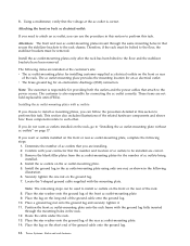
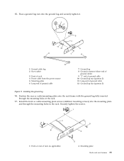
Place a ground lug nut onto the ground lug and securely tighten it. 1 Ground cable lug 2 Star washer 3 Front of rack 4 Power cable from the power source 5 Mounting plate 6 Long end of ground cable 7 Ground lug 8 Ground connector (short end of ground cable) 9 "Y" end of ground cable 10 Ground lug nut (...
Place a ground lug nut onto the ground lug and securely tighten it. 1 Ground cable lug 2 Star washer 3 Front of rack 4 Power cable from the power source 5 Mounting plate 6 Long end of ground cable 7 Ground lug 8 Ground connector (short end of ground cable) 9 "Y" end of ground cable 10 Ground lug nut (...
User Guide
Page 28
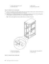
... be located at the rear of the ground cable to the rack frame, either near the center in the rack. Securely tighten the screws. 2 Power cable from power source 3 Button-head screw 5 Allen wrench 6 Long end of the rack. 1 Bus bar mounting plate 2 Lock washer (quantity 2) Figure 13. Connect the Y-shaped end... the rack or to the ground bus bar at either the top or bottom of ground cable Figure 12. Installing the back mounting plate 16 Power Systems: Racks and rack features 3 Hex screws (M5 x 20) (quantity 2) 4 Ground bus bar
... be located at the rear of the ground cable to the rack frame, either near the center in the rack. Securely tighten the screws. 2 Power cable from power source 3 Button-head screw 5 Allen wrench 6 Long end of the rack. 1 Bus bar mounting plate 2 Lock washer (quantity 2) Figure 13. Connect the Y-shaped end... the rack or to the ground bus bar at either the top or bottom of ground cable Figure 12. Installing the back mounting plate 16 Power Systems: Racks and rack features 3 Hex screws (M5 x 20) (quantity 2) 4 Ground bus bar