
User Guide
Page 5
... Removing a 7014-T00 or 7014-T42 side panel 21 Replacing a 7014-T00 or 7014-T42 side panel 22 Removing and replacing 7014-T00 or 7014-T42 trim panels 22 Removing the 7014-T00 or 7014-T42 trim panels 22 Replacing the 7014-T00 or 7014-T42 trim panels 23 Attaching the rack doors 24 Attaching a high-perforation front door 25 Rack safety notices 26 Installing the...
... Removing a 7014-T00 or 7014-T42 side panel 21 Replacing a 7014-T00 or 7014-T42 side panel 22 Removing and replacing 7014-T00 or 7014-T42 trim panels 22 Removing the 7014-T00 or 7014-T42 trim panels 22 Replacing the 7014-T00 or 7014-T42 trim panels 23 Attaching the rack doors 24 Attaching a high-perforation front door 25 Rack safety notices 26 Installing the...
User Guide
Page 7
... im Sinne § 2 der Bildschirmarbeitsverordnung geeignet. English source. English publication to install, operate, or service this guide: v DANGER notices call attention to be obtained by calling the IBM Hotline at 1-800-300-8751. The documentation contains the safety information in printed documentation...are fiber-optic based and that is potentially hazardous to people. Safety notices Safety notices may be installed inside or outside of an IT equipment rack. © Copyright IBM Corp. 2010, 2013 v v CAUTION notices call attention to the possibility of damage to a ...
... im Sinne § 2 der Bildschirmarbeitsverordnung geeignet. English source. English publication to install, operate, or service this guide: v DANGER notices call attention to be obtained by calling the IBM Hotline at 1-800-300-8751. The documentation contains the safety information in printed documentation...are fiber-optic based and that is potentially hazardous to people. Safety notices Safety notices may be installed inside or outside of an IT equipment rack. © Copyright IBM Corp. 2010, 2013 v v CAUTION notices call attention to the possibility of damage to a ...
User Guide
Page 8
...precautions: Electrical voltage and current from the devices. v When possible, use the IBM provided power cord for any power supply assembly. v Connect and disconnect cables as described in the installation and configuration procedures. Remove the signal cables from the outlets. 3. Attach the power...one hand only to the outlets. 5. Ensure that will be equipped with the IBM provided power cord. DANGER When working on or around the system, observe the following procedures when installing, moving, or opening covers on this product or attached devices. v The product ...
...precautions: Electrical voltage and current from the devices. v When possible, use the IBM provided power cord for any power supply assembly. v Connect and disconnect cables as described in the installation and configuration procedures. Remove the signal cables from the outlets. 3. Attach the power...one hand only to the outlets. 5. Ensure that will be equipped with the IBM provided power cord. DANGER When working on or around the system, observe the following procedures when installing, moving, or opening covers on this product or attached devices. v The product ...

User Guide
Page 9
...refer to the rating labels located on the equipment in the rack to prevent an electrical shock. v (For fixed drawers.) This drawer is compromised. v Always install stabilizer brackets on or around your rack-mounted devices. v Rack-mounted devices are not attached to fall out of the circuits does not compromise the... of the system or the devices that is not blocked or reduced on the rack cabinet. v (For sliding drawers.) Do not pull out or install any side, front, or back of a unit used as shelves or work spaces. Attempting to move the drawer partially or completely out of the ...
...refer to the rating labels located on the equipment in the rack to prevent an electrical shock. v (For fixed drawers.) This drawer is compromised. v Always install stabilizer brackets on or around your rack-mounted devices. v Rack-mounted devices are not attached to fall out of the circuits does not compromise the... of the system or the devices that is not blocked or reduced on the rack cabinet. v (For sliding drawers.) Do not pull out or install any side, front, or back of a unit used as shelves or work spaces. Attempting to move the drawer partially or completely out of the ...
User Guide
Page 10
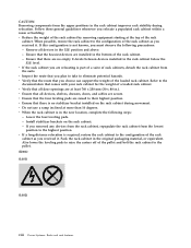
...position to their highest position. v If a long-distance relocation is required, restore the rack cabinet to the documentation that all door openings are installed in the rack cabinet below the 32U level. When possible, restore the rack cabinet to the pallet. (R002) (L001) (L002) viii ...the 32U position and above. - Remove all devices, shelves, drawers, doors, and cables are relocating is in .). Lower the four leveling pads. - Install stabilizer brackets on the rack cabinet during relocation. v Do not use a ramp inclined at the top of the rack cabinet. - v Inspect the ...
...position to their highest position. v If a long-distance relocation is required, restore the rack cabinet to the documentation that all door openings are installed in the rack cabinet below the 32U level. When possible, restore the rack cabinet to the pallet. (R002) (L001) (L002) viii ...the 32U position and above. - Remove all devices, shelves, drawers, doors, and cables are relocating is in .). Lower the four leveling pads. - Install stabilizer brackets on the rack cabinet during relocation. v Do not use a ramp inclined at the top of the rack cabinet. - v Inspect the ...
User Guide
Page 12
... ports of this equipment must be shielded and grounded at greater than 100°C (212°F) v ___ Repair or disassemble Exchange only with the IBM-approved part. The DC battery return terminal shall not be metallically connected to intrabuilding or unexposed wiring or cabling only. For information, call . (C003... connection to the interfaces that have been designated as instructed by local regulations. x Power Systems: Racks and rack features In the United States, IBM has a process for installation in GR-1089-CORE) and require isolation from the exposed OSP cabling.
... ports of this equipment must be shielded and grounded at greater than 100°C (212°F) v ___ Repair or disassemble Exchange only with the IBM-approved part. The DC battery return terminal shall not be metallically connected to intrabuilding or unexposed wiring or cabling only. For information, call . (C003... connection to the interfaces that have been designated as instructed by local regulations. x Power Systems: Racks and rack features In the United States, IBM has a process for installation in GR-1089-CORE) and require isolation from the exposed OSP cabling.
User Guide
Page 13
... and 7953-94Y racks. 7014-T00 and 7014-T42 racks Use this service. For expansion units and disk drive enclosures, see "Installing the rack security kit" on page 28 after you . Installing the rack Use this information to install the related components of a rack contains information for you have installed the rack. © Copyright IBM Corp. 2010, 2013...
... and 7953-94Y racks. 7014-T00 and 7014-T42 racks Use this service. For expansion units and disk drive enclosures, see "Installing the rack security kit" on page 28 after you . Installing the rack Use this information to install the related components of a rack contains information for you have installed the rack. © Copyright IBM Corp. 2010, 2013...
User Guide
Page 14
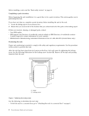
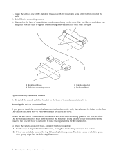
... unit in an accessory box. 2. Completing a parts inventory: Before beginning the rack installation it is needed to perform this task. Tightening the locking screw Use the following illustration for your country) v IBM Rochester Manufacturing Automated Information Line at IBM Directory of the features that you ordered and all the tape and packing materials...
... unit in an accessory box. 2. Completing a parts inventory: Before beginning the rack installation it is needed to perform this task. Tightening the locking screw Use the following illustration for your country) v IBM Rochester Manufacturing Automated Information Line at IBM Directory of the features that you ordered and all the tape and packing materials...
User Guide
Page 15
... stabilizer brackets, see "Attaching the front or back ac electrical outlet" on page 14 for instruction about installing the ac outlet-mounting plates. This section helps you determine whether stabilizer brackets are used only if you will not be bolting the rack to ... are necessary and describes how to attach them if needed until it contacts the surface on page 9. Racks and rack features 3 The rack must be installed in this section. Rotate each leveling foot. 2. Adjusting the leveling feet Attaching the stabilizer brackets: You might need to level the rack, use the procedure...
... stabilizer brackets, see "Attaching the front or back ac electrical outlet" on page 14 for instruction about installing the ac outlet-mounting plates. This section helps you determine whether stabilizer brackets are used only if you will not be bolting the rack to ... are necessary and describes how to attach them if needed until it contacts the surface on page 9. Racks and rack features 3 The rack must be installed in this section. Rotate each leveling foot. 2. Adjusting the leveling feet Attaching the stabilizer brackets: You might need to level the rack, use the procedure...
User Guide
Page 16
... mounting screws alternately until they are held in its predetermined location, and tighten the locking screws on the back of the rack. 2. To install the second stabilizer bracket on the casters. 2. See the following step: 1. Align the slots of one of the stabilizer brackets with the ... contractor must be bolted to a concrete floor, complete the following illustration. 4 Power Systems: Racks and rack features The trim panels are installed, remove the top, left, and right trim panels. Attaching the stabilizer brackets 4. This section describes how to the concrete floor...
... mounting screws alternately until they are held in its predetermined location, and tighten the locking screws on the back of the rack. 2. To install the second stabilizer bracket on the casters. 2. See the following step: 1. Align the slots of one of the stabilizer brackets with the ... contractor must be bolted to a concrete floor, complete the following illustration. 4 Power Systems: Racks and rack features The trim panels are installed, remove the top, left, and right trim panels. Attaching the stabilizer brackets 4. This section describes how to the concrete floor...

User Guide
Page 17
... kit. Grasp the door firmly with both hands and pull it away from the hinges. 4. If they are installing an ac-powered rack, temporarily install the lower plastic isolator bushings to help you are installed, remove the front and rear doors. Unlock and open the door. If you locate the mounting locations for...
... kit. Grasp the door firmly with both hands and pull it away from the hinges. 4. If they are installing an ac-powered rack, temporarily install the lower plastic isolator bushings to help you are installed, remove the front and rear doors. Unlock and open the door. If you locate the mounting locations for...

User Guide
Page 18
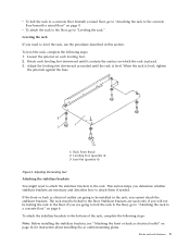
Top plastic isolator bushing c. Reposition the rack-mounting plates under the rack. 7. Thick flat washer d. Installing ac-power mounting plates 1 Rack chassis 2 Rack-mounting bolt 3 Thin washer 4 Top plastic isolator bushing 5 Thick washer 6 Spacer 7 Jam nut 8 ...Leveling foot 9 Lower plastic isolator bushing (used only on dc powered systems) ac Typical leveling foot installation for an ac-powered rack dc Typical leveling foot installation for an dc-powered rack 6. Thin washer b. Spacer 8. Insert a rack-mounting bolt assembly through each rack-mounting bolt....
Top plastic isolator bushing c. Reposition the rack-mounting plates under the rack. 7. Thick flat washer d. Installing ac-power mounting plates 1 Rack chassis 2 Rack-mounting bolt 3 Thin washer 4 Top plastic isolator bushing 5 Thick washer 6 Spacer 7 Jam nut 8 ...Leveling foot 9 Lower plastic isolator bushing (used only on dc powered systems) ac Typical leveling foot installation for an ac-powered rack dc Typical leveling foot installation for an dc-powered rack 6. Thin washer b. Spacer 8. Insert a rack-mounting bolt assembly through each rack-mounting bolt....

User Guide
Page 19
.... Move the rack so that it is clear of both stabilizer brackets. 20. If you are accessible through the opening in both areas that are installing an ac-powered rack, remove the bottom isolator bushing from each of the rack. 13.
.... Move the rack so that it is clear of both stabilizer brackets. 20. If you are accessible through the opening in both areas that are installing an ac-powered rack, remove the bottom isolator bushing from each of the rack. 13.

User Guide
Page 20
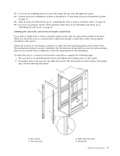
.... Position the rack over the concrete anchors. 26. When the rack is level. Note: You must be determined by the mechanical contractor who will be installing the rack-mounting plate. 27. Be sure that are accessible. Position the stabilizer bracket over the stabilizer bracket. 28. Insert each of the rack-mounting...
.... Position the rack over the concrete anchors. 26. When the rack is level. Note: You must be determined by the mechanical contractor who will be installing the rack-mounting plate. 27. Be sure that are accessible. Position the stabilizer bracket over the stabilizer bracket. 28. Insert each of the rack-mounting...
User Guide
Page 21
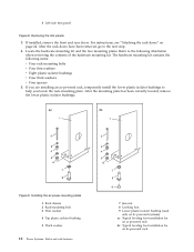
...in place with spring clips. Obtain the services of a mechanical contractor to attach the rack-mounting plates to meet the requirements for the installation. The mechanical contractor needs to determine that the hardware being used to secure the rack-mounting plates to the concrete floor is sufficient ...lays beneath a raised floor, follow the procedure described in its predetermined location and tighten the locking screws on your rack in this section. If installed, remove the top, left , and right trim panel. 34. Connect the power distribution system as described in the rack, the rack must ...
...in place with spring clips. Obtain the services of a mechanical contractor to attach the rack-mounting plates to meet the requirements for the installation. The mechanical contractor needs to determine that the hardware being used to secure the rack-mounting plates to the concrete floor is sufficient ...lays beneath a raised floor, follow the procedure described in its predetermined location and tighten the locking screws on your rack in this section. If installed, remove the top, left , and right trim panel. 34. Connect the power distribution system as described in the rack, the rack must ...
User Guide
Page 22
... plastic isolator bushings v Four thick washers v Four spacers 5. After the mounting plate has been correctly located, remove the lower plastic isolator bushings. Installing the ac power-mounting plates 1 Rack chassis 2 Rack-mounting bolt 3 Thin washer 4 Top plastic isolator bushing 5 Thick washer 10 Power Systems:.... For instructions, see "Attaching the rack doors" on dc powered systems) ac Typical leveling foot installation for an ac-powered rack dc Typical leveling foot installation for an dc-powered rack Locate the hardware mounting kit and the two mounting plates. The hardware ...
... plastic isolator bushings v Four thick washers v Four spacers 5. After the mounting plate has been correctly located, remove the lower plastic isolator bushings. Installing the ac power-mounting plates 1 Rack chassis 2 Rack-mounting bolt 3 Thin washer 4 Top plastic isolator bushing 5 Thick washer 10 Power Systems:.... For instructions, see "Attaching the rack doors" on dc powered systems) ac Typical leveling foot installation for an ac-powered rack dc Typical leveling foot installation for an dc-powered rack Locate the hardware mounting kit and the two mounting plates. The hardware ...
User Guide
Page 23
... rack-mounting plate when securing the rack to the threaded hole areas as possible. a. Mark the plate bolt-down holes that the mounting bolts are installing an ac-powered rack, remove the bottom isolator bushing from the raised-floor panel to each of the leveling feet. 15. Mark the raised-floor...
... rack-mounting plate when securing the rack to the threaded hole areas as possible. a. Mark the plate bolt-down holes that the mounting bolts are installing an ac-powered rack, remove the bottom isolator bushing from the raised-floor panel to each of the leveling feet. 15. Mark the raised-floor...

User Guide
Page 24
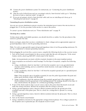
... each caster. 36. Otherwise, torque the four bolts to the floor 30. Replace all raised-floor panels that may have multiple racks that are not installing doors on your anchor bolts, secure the back stabilizer bracket on page 33. Align the rack over the front and rear stabilizer brackets. 33. Using... your rack, install the top, left, and right trim panel. 12 Power Systems: Racks and rack features Securing the rack to 54 67 newton-meters (40 - 50 foot...
... each caster. 36. Otherwise, torque the four bolts to the floor 30. Replace all raised-floor panels that may have multiple racks that are not installing doors on your anchor bolts, secure the back stabilizer bracket on page 33. Align the rack over the front and rear stabilizer brackets. 33. Using... your rack, install the top, left, and right trim panel. 12 Power Systems: Racks and rack features Securing the rack to 54 67 newton-meters (40 - 50 foot...
User Guide
Page 25
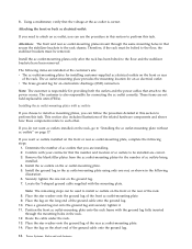
...to the receptacle case. To the circuit breaker switch, attach tag S229-0237, which indicates the presence of the phase pins. Some receptacles are installing rack doors, go to "Attaching the rack doors" on page 14. 41. Using a multimeter, check for infinite resistance between phases. Using ...in step 2 are made with the metal. The readings should check the ac outlets. For this type of the checks made in the usual installed position. 2. b. For instructions, see "Power distribution unit" on the branch circuit breaker. 7. Note: All measurements are not correct, remove ...
...to the receptacle case. To the circuit breaker switch, attach tag S229-0237, which indicates the presence of the phase pins. Some receptacles are installing rack doors, go to "Attaching the rack doors" on page 14. 41. Using a multimeter, check for infinite resistance between phases. Using ...in step 2 are made with the metal. The readings should check the ac outlets. For this type of the checks made in the usual installed position. 2. b. For instructions, see "Power distribution unit" on the branch circuit breaker. 7. Note: All measurements are not correct, remove ...
User Guide
Page 26
... ground lug fully inserted through the same mounting holes in the ac outlet-mounting plate using only one nut on the ground lug. 7. Install the ac outlet-mounting plates only after the rack has been bolted to each other. Note: The customer is responsible for providing both the... 6. These items are correct. 3. Locate the Y-shaped ground cable supplied with ac outlets: If you choose to attach an ac outlet, you are installed at the ac outlet is also responsible for connecting the ac outlet correctly. Position the front ac outlet-mounting plate onto the rack frame with...
... ground lug fully inserted through the same mounting holes in the ac outlet-mounting plate using only one nut on the ground lug. 7. Install the ac outlet-mounting plates only after the rack has been bolted to each other. Note: The customer is responsible for providing both the... 6. These items are correct. 3. Locate the Y-shaped ground cable supplied with ac outlets: If you choose to attach an ac outlet, you are installed at the ac outlet is also responsible for connecting the ac outlet correctly. Position the front ac outlet-mounting plate onto the rack frame with...