
User Guide
Page 5
... or 7014-T42 side panel 21 Replacing a 7014-T00 or 7014-T42 side panel 22 Removing and replacing 7014-T00 or 7014-T42 trim panels 22 Removing the 7014-T00 or 7014-T42 trim panels 22 Replacing the 7014-T00 or 7014-T42 trim panels 23 Attaching the rack doors 24 Attaching a high-perforation front door 25 Rack safety notices 26 Installing the rack security kit... and 7953-94Y racks 50 Notices 51 Trademarks 52 Electronic emission notices 52 Class A Notices 52 Class B Notices 56 Terms and conditions 59 © Copyright IBM Corp. 2010, 2013 iii
... or 7014-T42 side panel 21 Replacing a 7014-T00 or 7014-T42 side panel 22 Removing and replacing 7014-T00 or 7014-T42 trim panels 22 Removing the 7014-T00 or 7014-T42 trim panels 22 Replacing the 7014-T00 or 7014-T42 trim panels 23 Attaching the rack doors 24 Attaching a high-perforation front door 25 Rack safety notices 26 Installing the rack security kit... and 7953-94Y racks 50 Notices 51 Trademarks 52 Electronic emission notices 52 Class A Notices 52 Class B Notices 56 Terms and conditions 59 © Copyright IBM Corp. 2010, 2013 iii
User Guide
Page 13
... units. - For covers and parts, see "Installing the rack security kit" on page 28 after you have installed the rack. © Copyright IBM Corp. 2010, 2013 1 If you . March 2013 Content updates include the following: v Miscellaneous changes were made to install the 7014-T00 and 7014-T42 racks. October 2012 Content updates include the following : v Procedure...
... units. - For covers and parts, see "Installing the rack security kit" on page 28 after you have installed the rack. © Copyright IBM Corp. 2010, 2013 1 If you . March 2013 Content updates include the following: v Miscellaneous changes were made to install the 7014-T00 and 7014-T42 racks. October 2012 Content updates include the following : v Procedure...

User Guide
Page 20
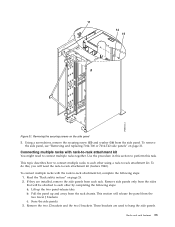
...connected in a suite (bolted to each other), go to "Connecting multiple racks with rack-to the concrete floor. Securely bolt the front stabilizer bracket to the concrete floor. Securely bolt the back stabilizer bracket to the concrete floor. 25. Note: The size of the anchor bolts and concrete anchors... must use a minimum of two anchor bolts for each of the holes in each rack-mounting plate to securely attach the plate to -rack attachment kit" on each caster. 31. Tighten the locking screw on page 33. Adjusting the leveling feet 32. Be sure that are...
...connected in a suite (bolted to each other), go to "Connecting multiple racks with rack-to the concrete floor. Securely bolt the front stabilizer bracket to the concrete floor. Securely bolt the back stabilizer bracket to the concrete floor. 25. Note: The size of the anchor bolts and concrete anchors... must use a minimum of two anchor bolts for each of the holes in each rack-mounting plate to securely attach the plate to -rack attachment kit" on each caster. 31. Tighten the locking screw on page 33. Adjusting the leveling feet 32. Be sure that are...

User Guide
Page 24
... as needed until the rack is level, tighten the jam nuts against the base of the rack. 37. Insert each other), go to -rack attachment kit" on page 33. Adjust the leveling feet downward as a suite (bolted to each of the raised floor and through a leveling foot. 34. Replace all... 4 Thick washer 5 Spacer 6 Jam nut 7 Leveling foot 8 Lower plastic isolator bushing (used only on dc-powered systems) 9 Stabilizer brackets 10 Threaded hole (used to secure the rack to mounting plate.) 11 Anchor bolt hole 12 Traced pattern (pattern to 54 67 newton-meters (40 - 50 foot-pounds). 38. Using your...
... as needed until the rack is level, tighten the jam nuts against the base of the rack. 37. Insert each other), go to -rack attachment kit" on page 33. Adjust the leveling feet downward as a suite (bolted to each of the raised floor and through a leveling foot. 34. Replace all... 4 Thick washer 5 Spacer 6 Jam nut 7 Leveling foot 8 Lower plastic isolator bushing (used only on dc-powered systems) 9 Stabilizer brackets 10 Threaded hole (used to secure the rack to mounting plate.) 11 Anchor bolt hole 12 Traced pattern (pattern to 54 67 newton-meters (40 - 50 foot-pounds). 38. Using your...
User Guide
Page 33
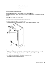
...7014-T00 or 7014-T42 side panel: Use the procedure in this section to perform this procedure for the other side panel. Use the procedures in this section to remove a side panel on both sides) 3 Power distribution panel 4 Front of the side panel slightly toward you must remove the securing ... rack. Removing the side panel Note: If your rack uses a ruggedized kit, you . 3. Racks and rack features 21 Tilt the top of rack Figure 18. Reinstalling the cable channel cover Removing and replacing 7014-T00 or 7014-T42 side panels Learn how to be removed. To remove a side panel, ...
...7014-T00 or 7014-T42 side panel: Use the procedure in this section to perform this procedure for the other side panel. Use the procedures in this section to remove a side panel on both sides) 3 Power distribution panel 4 Front of the side panel slightly toward you must remove the securing ... rack. Removing the side panel Note: If your rack uses a ruggedized kit, you . 3. Racks and rack features 21 Tilt the top of rack Figure 18. Reinstalling the cable channel cover Removing and replacing 7014-T00 or 7014-T42 side panels Learn how to be removed. To remove a side panel, ...
User Guide
Page 34
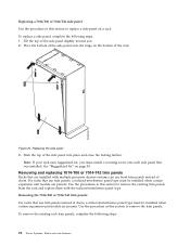
Place the bottom of the side panel onto the ridge on the bottom of doors. Replacing the side panel 3. Note: If your rack uses ruggedized kit, you . 2. Use the procedure in this section to replace a side panel on page 30. To remove the existing rack trim panels, complete the ...with multiple processor drawer systems can use trim panels instead of the side panel slightly toward you must install a securing screw into place and close the locking latches. Replacing a 7014-T00 or 7014-T42 side panel: Use the procedure in this section to remove the trim panels. To replace a side panel, ...
Place the bottom of the side panel onto the ridge on the bottom of doors. Replacing the side panel 3. Note: If your rack uses ruggedized kit, you . 2. Use the procedure in this section to replace a side panel on page 30. To remove the existing rack trim panels, complete the ...with multiple processor drawer systems can use trim panels instead of the side panel slightly toward you must install a securing screw into place and close the locking latches. Replacing a 7014-T00 or 7014-T42 side panel: Use the procedure in this section to remove the trim panels. To replace a side panel, ...
User Guide
Page 38
... You need to the equipment or personal injury could occur. 26 Power Systems: Racks and rack features Adjust the latch so the door latches securely. Before installing a rack, rack features, or a system or expansion unit into the hinge. 5. Install the door latch on the right ..., read the rack safety notices before installing equipment. Attention: If you do not have a rail kit designed for the equipment in the non-IBM rack, do not install the equipment into a non-IBM rack, the rack must comply with the Electronics Industries Association (EIA) 310D specifications. Figure 24.
... You need to the equipment or personal injury could occur. 26 Power Systems: Racks and rack features Adjust the latch so the door latches securely. Before installing a rack, rack features, or a system or expansion unit into the hinge. 5. Install the door latch on the right ..., read the rack safety notices before installing equipment. Attention: If you do not have a rail kit designed for the equipment in the non-IBM rack, do not install the equipment into a non-IBM rack, the rack must comply with the Electronics Industries Association (EIA) 310D specifications. Figure 24.

User Guide
Page 40
... related hardware components and shows how these components relate to each other. Each kit contains: - Rack lock - Bracket - Verify the inventory in this section to install the rack security kit. Read the "Rack safety notices" on page 26. 2. Two keys 2 Two security slide bars 28 Power Systems: Racks and rack features Screw - Use the...
... related hardware components and shows how these components relate to each other. Each kit contains: - Rack lock - Bracket - Verify the inventory in this section to install the rack security kit. Read the "Rack safety notices" on page 26. 2. Two keys 2 Two security slide bars 28 Power Systems: Racks and rack features Screw - Use the...

User Guide
Page 41
... (10) on the side cover panel. Unlatch right-side cover panel and lean the panel back so that secures the lock to install the second lock on the bottom of the door. 5. Rack security kit inventory 3. On the inside of the rail. Repeat steps 3 and 4 to the rack door. Note: Each ... long tabs on the back rack door. 6. a. 3 Two locked/unlocked stickers Figure 25. Remove the existing door latch. Secure the lock by attaching the lock bracket (5) with the ruggedized kit, remove the jam nut and hex nut from the existing door latch and reinstall both nuts on either the right...
... (10) on the side cover panel. Unlatch right-side cover panel and lean the panel back so that secures the lock to install the second lock on the bottom of the door. 5. Rack security kit inventory 3. On the inside of the rail. Repeat steps 3 and 4 to the rack door. Note: Each ... long tabs on the back rack door. 6. a. 3 Two locked/unlocked stickers Figure 25. Remove the existing door latch. Secure the lock by attaching the lock bracket (5) with the ruggedized kit, remove the jam nut and hex nut from the existing door latch and reinstall both nuts on either the right...
User Guide
Page 42
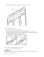
...and over the unlocked symbol (12), when the slide bar is over the locked symbol (11), as shown in the ruggedized kit. e. Repeat the procedure for the left side of the cover panel so that you can perform these tasks. 30 Power Systems...: Racks and rack features Ruggedized kit You might need to the front of the rack. Note: When installed correctly, the slide rail moves from front to... f. Place a locked/unlocked sticker on the inside of the rack. Figure 28. Figure 27. Installing a security slide bar c.
...and over the unlocked symbol (12), when the slide bar is over the locked symbol (11), as shown in the ruggedized kit. e. Repeat the procedure for the left side of the cover panel so that you can perform these tasks. 30 Power Systems...: Racks and rack features Ruggedized kit You might need to the front of the rack. Note: When installed correctly, the slide rail moves from front to... f. Place a locked/unlocked sticker on the inside of the rack. Figure 28. Figure 27. Installing a security slide bar c.
User Guide
Page 43
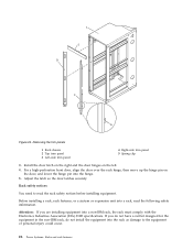
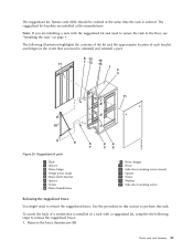
...Note: If you need to the floor, see "Installing the rack" on page 1. Ruggedized kit parts 1 Rack 2 Spacer 3 Brace hinge 4 Hinge pivot studs 5 Brace latch bracket 6 Spacer 7 Screw 8 Brace thumbscrew 9 Brace hinges 10 Brace 11 Side-door securing screw mount 12 Spacer 13 Screw 14 Washer 15 Side door...to uninstall and reinstall a part. The following steps to release the ruggedized brace: 1. Use the procedure in a rack with the ruggedized kit and need to secure the rack to release the ruggedized brace. To access the back of each bracket and hinges in the event that is ordered. Figure ...
...Note: If you need to the floor, see "Installing the rack" on page 1. Ruggedized kit parts 1 Rack 2 Spacer 3 Brace hinge 4 Hinge pivot studs 5 Brace latch bracket 6 Spacer 7 Screw 8 Brace thumbscrew 9 Brace hinges 10 Brace 11 Side-door securing screw mount 12 Spacer 13 Screw 14 Washer 15 Side door...to uninstall and reinstall a part. The following steps to release the ruggedized brace: 1. Use the procedure in a rack with the ruggedized kit and need to secure the rack to release the ruggedized brace. To access the back of each bracket and hinges in the event that is ordered. Figure ...

User Guide
Page 44
... rack. Swing the brace (10) out of the rack. 3. Locate the securing screw mount (11) for the side door that secure the side panels to perform this task. Releasing the side panel with a ruggedized kit: You might need to access systems 2. Use this procedure to the rack.... To remove a securing screw, complete the following steps: 1. Figure 30. The ruggedized kit contains securing screws that will be removed. 32 Power Systems: Racks and rack...
... rack. Swing the brace (10) out of the rack. 3. Locate the securing screw mount (11) for the side door that secure the side panels to perform this task. Releasing the side panel with a ruggedized kit: You might need to access systems 2. Use this procedure to the rack.... To remove a securing screw, complete the following steps: 1. Figure 30. The ruggedized kit contains securing screws that will be removed. 32 Power Systems: Racks and rack...
User Guide
Page 45
... on page 26. 2. Read the "Rack safety notices" on the side panel 3. b. c. Using a screwdriver, remove the securing screw (15) and washer (14) from the rack chassis. Use the procedure in this section to perform this , you will need to connect multiple racks ... topic describes how to connect multiple racks to -rack attachment kit, complete the following steps: a. If they are used to -rack attachment kit. Lift up and away from the side panel. To remove the side panel, see "Removing and replacing 7014-T00 or 7014-T42 side panels" on page 21. Remove the two Z brackets and...
... on page 26. 2. Read the "Rack safety notices" on the side panel 3. b. c. Using a screwdriver, remove the securing screw (15) and washer (14) from the rack chassis. Use the procedure in this section to perform this , you will need to connect multiple racks ... topic describes how to connect multiple racks to -rack attachment kit, complete the following steps: a. If they are used to -rack attachment kit. Lift up and away from the side panel. To remove the side panel, see "Removing and replacing 7014-T00 or 7014-T42 side panels" on page 21. Remove the two Z brackets and...
User Guide
Page 56
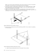
... rack has square mounting holes, attach cage nuts instead of nut clips to the rack cabinet by completing the following steps: Figure 45. Figure 44. Secure the long mounting brackets and the blank filler panel (A) to the specified EIA locations. Hold the PDU model at a slight angle and carefully insert it...
... rack has square mounting holes, attach cage nuts instead of nut clips to the rack cabinet by completing the following steps: Figure 45. Figure 44. Secure the long mounting brackets and the blank filler panel (A) to the specified EIA locations. Hold the PDU model at a slight angle and carefully insert it...
User Guide
Page 57
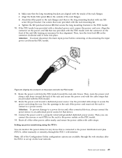
...a detached power cord, connect the power cord now. Then, you can monitor the power status for any device that was provided with the rack mounting kit. Then, turn the twist-lock (B) on the outside of the rack flanges. Attention: You must exit the rack to connect to the PDU model.... 10. Use screws that secure the long mounting brackets to a power source. Align the connector on the power cord (A) that is set up power monitoring using the PDU+: You ...
...a detached power cord, connect the power cord now. Then, you can monitor the power status for any device that was provided with the rack mounting kit. Then, turn the twist-lock (B) on the outside of the rack flanges. Attention: You must exit the rack to connect to the PDU model.... 10. Use screws that secure the long mounting brackets to a power source. Align the connector on the power cord (A) that is set up power monitoring using the PDU+: You ...