

Maintenance Manual
Page 33
... Power on will be connected to the printer parallel-port as a laptop, can be in hexadecimal code is the correct MAP for host program debug. Change the NO to YES, press the Pitch key, and printing from that point on configuration (Model A00) Serial attachment card Logic board (includes parallel attachment) Host cable Parallel and serial configuration - Refer to HEX DUMP=NO. or - Diagnosing Problems 33 Printing in hexadecimal code. Model 003: On the operator panel, press the Hex Print...
... Power on will be connected to the printer parallel-port as a laptop, can be in hexadecimal code is the correct MAP for host program debug. Change the NO to YES, press the Pitch key, and printing from that point on configuration (Model A00) Serial attachment card Logic board (includes parallel attachment) Host cable Parallel and serial configuration - Refer to HEX DUMP=NO. or - Diagnosing Problems 33 Printing in hexadecimal code. Model 003: On the operator panel, press the Hex Print...
Maintenance Manual
Page 45
... step 7 on (|) the printer. 4) Press the Stop key to print. 8) Verify the configuration information matches the host settings. "How To Run the Test b. printer operation. Table 6. The following items are no blank fanfold forms available, install two sheets of blank, fanfold forms in the IBM 4247 Printer Models 001, 002 User's Guide, SA24-4408 or IBM 4247 Printer Model 003 User's Guide, S544-5780 for the configuration to make the printer Not Ready (only the Power LED is using. Diagnosing Problems 45
... step 7 on (|) the printer. 4) Press the Stop key to print. 8) Verify the configuration information matches the host settings. "How To Run the Test b. printer operation. Table 6. The following items are no blank fanfold forms available, install two sheets of blank, fanfold forms in the IBM 4247 Printer Models 001, 002 User's Guide, SA24-4408 or IBM 4247 Printer Model 003 User's Guide, S544-5780 for the configuration to make the printer Not Ready (only the Power LED is using. Diagnosing Problems 45

Maintenance Manual
Page 110
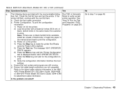
...: Forms Feed Problems (continued) Step Questions/Actions Yes 12. Are the forms jamming into the platen during a Load Go to step 17 on page 112. Check that the rear tractor is open or removed. e90aff12 Are the rear tractor and the rear paper door OK? 13. rear tractor paper door is installed correctly, and the Go to step 16 on configuring the tractor. or Form Feed operation? The following figure shows the positions of the rear tractor...
...: Forms Feed Problems (continued) Step Questions/Actions Yes 12. Are the forms jamming into the platen during a Load Go to step 17 on page 112. Check that the rear tractor is open or removed. e90aff12 Are the rear tractor and the rear paper door OK? 13. rear tractor paper door is installed correctly, and the Go to step 16 on configuring the tractor. or Form Feed operation? The following figure shows the positions of the rear tractor...

Maintenance Manual
Page 129
... Problems 129 Remove the printhead. Install a new printhead. Or "Logic Board - page 356. Mount forms, and try loading and parking forms several times. Are the cables OK? 3. Models 001 and 002, see "Logic Board - Chapter 1. See "Printhead" on Go to service. v Check the continuity of conductors 19 and 20 from the printhead. Load and park forms several times. Check the printhead cables. Model A00, see "Logic Board - Model 003" on page 370. b. If the error occurs...
... Problems 129 Remove the printhead. Install a new printhead. Or "Logic Board - page 356. Mount forms, and try loading and parking forms several times. Are the cables OK? 3. Models 001 and 002, see "Logic Board - Chapter 1. See "Printhead" on Go to service. v Check the continuity of conductors 19 and 20 from the printhead. Load and park forms several times. Check the printhead cables. Model A00, see "Logic Board - Model 003" on page 370. b. If the error occurs...

Maintenance Manual
Page 140
... 0160: Ribbon Feed and Ribbon Lift" on page 366. 053 MACHINE CHECK ERR 3XX The firmware detected a data integrity error. Or "Logic Board - If message remains, install a new Logic Board. Models 001 and 002" on page 366. 051 MACHINE CHECK ERR XXX Firmware error in supervisor code. Power off and power on the printer. Power off and power on the printer. Diagnosing Problems 140 Table 18. Model 003" on page 378. Power off and power on page...
... 0160: Ribbon Feed and Ribbon Lift" on page 366. 053 MACHINE CHECK ERR 3XX The firmware detected a data integrity error. Or "Logic Board - If message remains, install a new Logic Board. Models 001 and 002" on page 366. 051 MACHINE CHECK ERR XXX Firmware error in supervisor code. Power off and power on the printer. Power off and power on the printer. Diagnosing Problems 140 Table 18. Model 003" on page 378. Power off and power on page...

Maintenance Manual
Page 142
... IBM 4247 Printer Models 001, 002 User's Guide, SA24-4408). 2. Always lock the operator panel after completing your service procedures by performing this procedure. Power off and on page 94. 088 INVALID PAPER SOURCE USE MANUAL OR CHANGE CONFIGURATION Printer requires a paper source not installed. 1. v If the customer had the operator panel locked. Chapter 1. Diagnosing Problems 142 Table 18. Go to match the paper source requested (see error. Use the procedure in the Test Menu cannot be used. Error Messages for Models 001...
... IBM 4247 Printer Models 001, 002 User's Guide, SA24-4408). 2. Always lock the operator panel after completing your service procedures by performing this procedure. Power off and on page 94. 088 INVALID PAPER SOURCE USE MANUAL OR CHANGE CONFIGURATION Printer requires a paper source not installed. 1. v If the customer had the operator panel locked. Chapter 1. Diagnosing Problems 142 Table 18. Go to match the paper source requested (see error. Use the procedure in the Test Menu cannot be used. Error Messages for Models 001...

Maintenance Manual
Page 174
... the wheel position. 6. The print should be the same for print samples. Fanfold Form Printout Test Use this message. 3. Set the operator menu to check print quality, print wires, printhead wire shifter, carrier movement, paper feed, line skew, code level, and bidirectional (vertical) alignment. Chapter 2. Park the paper. 4. Load a single-sheet of symptoms and Figure 93 on page 338 for a list of paper into the print area. Pinch Roller Status/Sensor Tuning/Ribbon Feed and Lift Motors" on single-part forms, using a good ribbon. If...
... the wheel position. 6. The print should be the same for print samples. Fanfold Form Printout Test Use this message. 3. Set the operator menu to check print quality, print wires, printhead wire shifter, carrier movement, paper feed, line skew, code level, and bidirectional (vertical) alignment. Chapter 2. Park the paper. 4. Load a single-sheet of symptoms and Figure 93 on page 338 for a list of paper into the print area. Pinch Roller Status/Sensor Tuning/Ribbon Feed and Lift Motors" on single-part forms, using a good ribbon. If...

Maintenance Manual
Page 177
... Micro ↓ key using the new adjustment value. Install fanfold paper in the rear tractor assembly. 14. A block of the Es will feed to the top of the first print-line on the first-print line. Note the position of the paper, press the Load/Form Feed key. Install the fanfold paper in the tractor assembly. Note: X can be printed on the paper. 17. Each unit is First print-line REar tractor ADJustment 12. To run the rear first print-line test, ensure a tractor assembly...
... Micro ↓ key using the new adjustment value. Install fanfold paper in the rear tractor assembly. 14. A block of the Es will feed to the top of the first print-line on the first-print line. Note the position of the paper, press the Load/Form Feed key. Install the fanfold paper in the tractor assembly. Note: X can be printed on the paper. 17. Each unit is First print-line REar tractor ADJustment 12. To run the rear first print-line test, ensure a tractor assembly...

Maintenance Manual
Page 193
... 370. Chapter 2. Run T&D21 to verify sensor operation. Diagnostics 193 Table 27. Model A00" on page 370. 3. TD (**) FRU 3 12 Ribbon Sense Failure 1. See "Sensor Cable Assembly" on page 441. Replace the sensor cable assembly. If sensors are not operational: v Replace the logic board. T&D Error Messages and Action (continued) Error Message Description Action TD (**) FRU 3 11 Paper Sense Failure 1. Clear paper jam. 2. Replace the ribbon drive motor. See "Logic Board - See "Sensor Cable Assembly" on page 441. See "Logic...
... 370. Chapter 2. Run T&D21 to verify sensor operation. Diagnostics 193 Table 27. Model A00" on page 370. 3. TD (**) FRU 3 12 Ribbon Sense Failure 1. See "Sensor Cable Assembly" on page 441. Replace the sensor cable assembly. If sensors are not operational: v Replace the logic board. T&D Error Messages and Action (continued) Error Message Description Action TD (**) FRU 3 11 Paper Sense Failure 1. Clear paper jam. 2. Replace the ribbon drive motor. See "Logic Board - See "Sensor Cable Assembly" on page 441. See "Logic...

Maintenance Manual
Page 198
Load the printer with at zero. Press the Test key. Press the Enter key, and wait for the configuration to print the configuration. 2. To print a custom set on the operator panel display in the Print Error Log. b. If the Code Description existed in the list. If fewer than 8 Code Descriptions are lighted). 3. The current printer configuration is correct, use the Printer Configuration Test. 6. Press the Stop key to make the printer Not Ready (only the Power and Online LED...
Load the printer with at zero. Press the Test key. Press the Enter key, and wait for the configuration to print the configuration. 2. To print a custom set on the operator panel display in the Print Error Log. b. If the Code Description existed in the list. If fewer than 8 Code Descriptions are lighted). 3. The current printer configuration is correct, use the Printer Configuration Test. 6. Press the Stop key to make the printer Not Ready (only the Power and Online LED...

Maintenance Manual
Page 199
.... 6. Press the Menu key. 8. '4247 OPERATOR TESTS' is lighted). 5. Diagnostics 199 Select the paper path from the customer. Press the Stop key to print. NOT READY' appears. 7. wait for the error log to make the printer Not Ready (only the Power LED is displayed on line one and a test name on cycles v DP, DP text, and NLQ characters v Number (quantity) of barcodes v Number (quantity) of letter or legal size paper from which...
.... 6. Press the Menu key. 8. '4247 OPERATOR TESTS' is lighted). 5. Diagnostics 199 Select the paper path from the customer. Press the Stop key to print. NOT READY' appears. 7. wait for the error log to make the printer Not Ready (only the Power LED is displayed on line one and a test name on cycles v DP, DP text, and NLQ characters v Number (quantity) of barcodes v Number (quantity) of letter or legal size paper from which...

Maintenance Manual
Page 213
... printing T&D14 on page 168. Where XXXXX=OPEN or CLOSED. Load a single-sheet of paper into the front tractor (FF) or manual sheet feed tray (SS). 3. Ensure the paper bail and a ribbon cartridge are installed. 2. Park the paper. 4. If the previous message displays, follow the instructions in "T&D11 - or Press the Micro ↑ key to AFTA=0. 2. Set the operator menu to select SS. 4. Diagnostics 213 Note the wheel position. 6. Pinch Roller Status/Sensor...
... printing T&D14 on page 168. Where XXXXX=OPEN or CLOSED. Load a single-sheet of paper into the front tractor (FF) or manual sheet feed tray (SS). 3. Ensure the paper bail and a ribbon cartridge are installed. 2. Park the paper. 4. If the previous message displays, follow the instructions in "T&D11 - or Press the Micro ↑ key to AFTA=0. 2. Set the operator menu to select SS. 4. Diagnostics 213 Note the wheel position. 6. Pinch Roller Status/Sensor...

Maintenance Manual
Page 284
Test: Slide a sheet of the characters change using the Adjustments category, AFTA. c. On Models 001, 002, and 003, use the Wheel position where DARK begins and proceed to the chart below. Refer to step 6. If you get Example 3, change the T&D 12 value from 0 to -4, to slide with constant friction. Close the gap again and repeat this Paper Sliding number. 5. Setup: Install the front tractor, the bail assembly and a new...
Test: Slide a sheet of the characters change using the Adjustments category, AFTA. c. On Models 001, 002, and 003, use the Wheel position where DARK begins and proceed to the chart below. Refer to step 6. If you get Example 3, change the T&D 12 value from 0 to -4, to slide with constant friction. Close the gap again and repeat this Paper Sliding number. 5. Setup: Install the front tractor, the bail assembly and a new...

Maintenance Manual
Page 301
... tractor is as shown here. Check the paper bail setting. If adjustment is positioned so the LED light passes through the tractor holes. b. The paper bail is removed from the printer when the rear pull forms path is not lighted, replace the tractor assembly. 3. Chapter 5. If you should be able to see the red dot of the tractor sensor. e. Removals and Adjustments 301 Mount forms onto the tractor pins. While holding the paper in the forms. a. d. If adjusting the sensor...
... tractor is as shown here. Check the paper bail setting. If adjustment is positioned so the LED light passes through the tractor holes. b. The paper bail is removed from the printer when the rear pull forms path is not lighted, replace the tractor assembly. 3. Chapter 5. If you should be able to see the red dot of the tractor sensor. e. Removals and Adjustments 301 Mount forms onto the tractor pins. While holding the paper in the forms. a. d. If adjusting the sensor...

Maintenance Manual
Page 339
... Paper Drive Check and print parallel to verify correct printer operation. A00, see "How To Run the Test and Diagnostic (T&D) Programs" on page 342) should be catching in printhead mask. 2 Skew test in NLQ mode. Look for light or missing dots. The 18-wire printhead xxB line segments (see Figure 93 on page 201. Install new printhead cable. 5. For Models 001, 002, and 003, see "Logic Board - page 370. Print the...
... Paper Drive Check and print parallel to verify correct printer operation. A00, see "How To Run the Test and Diagnostic (T&D) Programs" on page 342) should be catching in printhead mask. 2 Skew test in NLQ mode. Look for light or missing dots. The 18-wire printhead xxB line segments (see Figure 93 on page 201. Install new printhead cable. 5. For Models 001, 002, and 003, see "Logic Board - page 370. Print the...

Maintenance Manual
Page 341
..." on left margin should See "Main Paper Drive Check and print parallel to the edge of paper. Or "Logic Board - Chapter 5. Model 003" on page 301. Adjustment" on page 366. 3. page 333. 11 Print wire test. Look for light or missing 1. Model A00" on page 333. 13 See Line 5 above. 14 Skew test in draft mode. See "Printhead Drive Service Check" on page 370. Install a new logic board. The line should be even. Print Quality Tests and...
..." on left margin should See "Main Paper Drive Check and print parallel to the edge of paper. Or "Logic Board - Chapter 5. Model 003" on page 301. Adjustment" on page 366. 3. page 333. 11 Print wire test. Look for light or missing 1. Model A00" on page 333. 13 See Line 5 above. 14 Skew test in draft mode. See "Printhead Drive Service Check" on page 370. Install a new logic board. The line should be even. Print Quality Tests and...

Maintenance Manual
Page 561
... Test - T&D16, Models 001 and 002 217 C cable, power 481 cable diagrams 258 carriage drive belt adjustment 280 remove/install 420 service check 279 carriage motor remove/install 415 wiring 246 catalog, parts 457 Circuit Diagrams 240 configuration changing a value in the power on configuration menu 486 changing a value in the printer configuration menu 504 changing a value in the program configuration menu 493 coax configuration printout defaults 500 power on configuration menu chart 485 power on configuration printout defaults 485 561 Removal & Installation 359 B Base Code Compatibilities...
... Test - T&D16, Models 001 and 002 217 C cable, power 481 cable diagrams 258 carriage drive belt adjustment 280 remove/install 420 service check 279 carriage motor remove/install 415 wiring 246 catalog, parts 457 Circuit Diagrams 240 configuration changing a value in the power on configuration menu 486 changing a value in the printer configuration menu 504 changing a value in the program configuration menu 493 coax configuration printout defaults 500 power on configuration menu chart 485 power on configuration printout defaults 485 561 Removal & Installation 359 B Base Code Compatibilities...

Maintenance Manual
Page 563
... and Test Page Problems 152 location connectors 271 microcode modules 266 Locations 265 Logic Board - START 23 0110 - Network Print Server Attachment 59 0130 - Paper Path Sensor 66 0140 - Power Supply 75 0160 - Forms Feed Problems 101 0200 - 55 AFTA Errors 127 0210 - Ribbon Feed and Lift 89 0170 - Stacker 94 0180 - Attachment, Model A00 33 0121 - Automatic Sheet Feeder 26 0120 - Printhead Drive 70 0150 - Top Cover Interlock...
... and Test Page Problems 152 location connectors 271 microcode modules 266 Locations 265 Logic Board - START 23 0110 - Network Print Server Attachment 59 0130 - Paper Path Sensor 66 0140 - Power Supply 75 0160 - Forms Feed Problems 101 0200 - 55 AFTA Errors 127 0210 - Ribbon Feed and Lift 89 0170 - Stacker 94 0180 - Attachment, Model A00 33 0121 - Automatic Sheet Feeder 26 0120 - Printhead Drive 70 0150 - Top Cover Interlock...

Maintenance Manual
Page 564
... No Printed Characters 146 O operator panel cable wiring 259 lock and unlock 142, 499 remove/install 355 Operator Panel and Miscellaneous Problems 149 P paper feed motor drive belt 448 remove/install 447 wiring 248 Paper Paths 158 paper specifications 534 Parallel Connector 273 Parts Catalog 457 Paths 531 Pin 18 +5V Jumper Locations 273 position, covers service 275 power cord 481 power supply MAP 75 power supply (continued) remove/install 400 Print Quality Failures 146 print quality service check fanfold printout 338 manual sheet feed printout 343 print test, how to print Model...
... No Printed Characters 146 O operator panel cable wiring 259 lock and unlock 142, 499 remove/install 355 Operator Panel and Miscellaneous Problems 149 P paper feed motor drive belt 448 remove/install 447 wiring 248 Paper Paths 158 paper specifications 534 Parallel Connector 273 Parts Catalog 457 Paths 531 Pin 18 +5V Jumper Locations 273 position, covers service 275 power cord 481 power supply MAP 75 power supply (continued) remove/install 400 Print Quality Failures 146 print quality service check fanfold printout 338 manual sheet feed printout 343 print test, how to print Model...

Maintenance Manual
Page 565
... roller assembly 323 print quality fanfold printout 338 single sheet printout 343 printhead drive 333 ribbon feed/lift 330, 439 stacker, ASF 322 tractor assembly 325 Service Checks and Adjustments 279 Service Position 275 service position, covers 275 shield, lower plastic 451 specifications, forms 534 stack locations 541, 542, 543, 544 stacker cable wiring 261 MAP 94 motor wiring 255 service check 322 stacking recommendations 539 Start of Call 23 Supplies 531 T tear-off line adjustment 295 Test...
... roller assembly 323 print quality fanfold printout 338 single sheet printout 343 printhead drive 333 ribbon feed/lift 330, 439 stacker, ASF 322 tractor assembly 325 Service Checks and Adjustments 279 Service Position 275 service position, covers 275 shield, lower plastic 451 specifications, forms 534 stack locations 541, 542, 543, 544 stacker cable wiring 261 MAP 94 motor wiring 255 service check 322 stacking recommendations 539 Start of Call 23 Supplies 531 T tear-off line adjustment 295 Test...


