

User Guide
Page 9
... and fan assembly 31 Time required 31 Items required 31 Removing a power supply and fan assembly . . 31 Replacing a power supply and fan assembly . . 32 Removing the battery 33 Appendix. Contents Read this document xxiii Product documents xxiii Brocade documents xxiii IBM and Brocade product matrix . . . . . Introducing the SAN48B-5 . . 1 Switch capabilities 1 Switch components 2 Port...
... and fan assembly 31 Time required 31 Items required 31 Removing a power supply and fan assembly . . 31 Replacing a power supply and fan assembly . . 32 Removing the battery 33 Appendix. Contents Read this document xxiii Product documents xxiii Brocade documents xxiii IBM and Brocade product matrix . . . . . Introducing the SAN48B-5 . . 1 Switch capabilities 1 Switch components 2 Port...

User Guide
Page 11
...+ with pull tab (shown without cable attached 20 9. Non-port side of battery holder 34 © Copyright IBM Corp. 2011 ix Position the front bracket 11 5. Position the rear and front brackets . . . . 12 7. Removing the power supply and fan assembly 32 16. Figures 1. Items in the cabinet . . . . . 12 6. Location of the switch... 24 13. Installing a 16 Gbps SFP+ with wire bail latch 20 10. Installing a cable 20 11. Port side LEDs 24 12. Port side view 3 2. Switch power supply and fan assemblies on the non-port side 30 15.
...+ with pull tab (shown without cable attached 20 9. Non-port side of battery holder 34 © Copyright IBM Corp. 2011 ix Position the front bracket 11 5. Position the rear and front brackets . . . . 12 7. Removing the power supply and fan assembly 32 16. Figures 1. Items in the cabinet . . . . . 12 6. Location of the switch... 24 13. Installing a 16 Gbps SFP+ with wire bail latch 20 10. Installing a cable 20 11. Port side LEDs 24 12. Port side view 3 2. Switch power supply and fan assemblies on the non-port side 30 15.

User Guide
Page 13
Sample caution notices xvi 2. Power supply specifications 36 11. Memory specifications 38 15. Brocade and IBM product and model number matrix xxiv 3. Non-port side LED patterns during normal operation 25 5. Power supply and fan assembly status LED behavior 30 8. Management options for slim ...rail rack mount kit . . . . 9 4. Access Gateway default port mapping . . . 40 © Copyright IBM Corp. 2011 xi Parts list for...
Sample caution notices xvi 2. Power supply specifications 36 11. Memory specifications 38 15. Brocade and IBM product and model number matrix xxiv 3. Non-port side LED patterns during normal operation 25 5. Power supply and fan assembly status LED behavior 30 8. Management options for slim ...rail rack mount kit . . . . 9 4. Access Gateway default port mapping . . . 40 © Copyright IBM Corp. 2011 xi Parts list for...
User Guide
Page 16
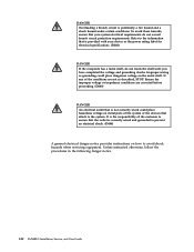
Ensure the improper voltage or impedance conditions are not as described, STOP. To avoid these hazards, ensure that your device or the power rating label for electrical specifications. (D002) DANGER If the receptacle has a metal shell, do not exceed branch circuit protection requirements. xiv SAN48B-5 Installation, Service, and ...
Ensure the improper voltage or impedance conditions are not as described, STOP. To avoid these hazards, ensure that your device or the power rating label for electrical specifications. (D002) DANGER If the receptacle has a metal shell, do not exceed branch circuit protection requirements. xiv SAN48B-5 Installation, Service, and ...
User Guide
Page 17
... when there is evidence of this unit only with multiple power cords. Remove the power cords from the connectors. 4. v Do not connect or disconnect any power supply assembly. Ensure that will be equipped with the IBM provided power cord. Remove the signal cables from the outlets. 3. To... electrical outlet. DANGER When working on the devices. (D005) Safety and environmental notices xv v When possible, use the IBM provided power cord for any equipment that the outlet supplies proper voltage and phase rotation according to this product during an electrical storm. Remove...
... when there is evidence of this unit only with multiple power cords. Remove the power cords from the connectors. 4. v Do not connect or disconnect any power supply assembly. Ensure that will be equipped with the IBM provided power cord. Remove the signal cables from the outlets. 3. To... electrical outlet. DANGER When working on the devices. (D005) Safety and environmental notices xv v When possible, use the IBM provided power cord for any equipment that the outlet supplies proper voltage and phase rotation according to this product during an electrical storm. Remove...
User Guide
Page 18
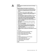
... by local regulations. (C014) CAUTION: This product is ... Read and comply with less severity than 18 kg (39.7 lb). Use this power cable with a 3-wire (two conductors and ground) power cable and plug. S. Department of lead (Pb) into the environment, do not burn. Discard the circuit card as instructed by the classification...
... by local regulations. (C014) CAUTION: This product is ... Read and comply with less severity than 18 kg (39.7 lb). Use this power cable with a 3-wire (two conductors and ground) power cable and plug. S. Department of lead (Pb) into the environment, do not burn. Discard the circuit card as instructed by the classification...

User Guide
Page 19
...-ROM drive, DVD-ROM drive, DVD-RAM drive, or laser module, which are no serviceable parts inside any cover or barrier that all power cords. (L003) Safety and environmental notices xvii Removing the covers of the hazard. To remove all electrical current from these sample safety labels...levels are present inside the device. CAUTION: This product might contain one connection to hazardous laser radiation. These can be equipped with multiple power cords. Do not open any component that has this label. (L001) DANGER Rack-mounted devices are often installed directly on the device does...
...-ROM drive, DVD-ROM drive, DVD-RAM drive, or laser module, which are no serviceable parts inside any cover or barrier that all power cords. (L003) Safety and environmental notices xvii Removing the covers of the hazard. To remove all electrical current from these sample safety labels...levels are present inside the device. CAUTION: This product might contain one connection to hazardous laser radiation. These can be equipped with multiple power cords. Do not open any component that has this label. (L001) DANGER Rack-mounted devices are often installed directly on the device does...
User Guide
Page 21
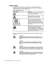
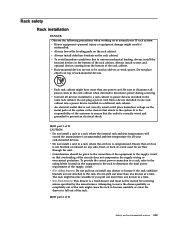
...might cause the rack to become unstable if you pull out more than one rack cabinet into a power device installed in a rack where the air flow is correctly wired and grounded to power devices installed in the rack cabinet when directed to fall out of the rack. (R001 part 2...mishandled. v Always lower the leveling pads on or around your rack-mounted devices. v Connect all power cords in the same rack cabinet. Ensure that the outlet is compromised. Do not plug a power cord from the bottom of the rack cabinet. v Always install stabilizer brackets on any drawer or ...
...might cause the rack to become unstable if you pull out more than one rack cabinet into a power device installed in a rack where the air flow is correctly wired and grounded to power devices installed in the rack cabinet when directed to fall out of the rack. (R001 part 2...mishandled. v Always lower the leveling pads on or around your rack-mounted devices. v Connect all power cords in the same rack cabinet. Ensure that the outlet is compromised. Do not plug a power cord from the bottom of the rack cabinet. v Always install stabilizer brackets on any drawer or ...

User Guide
Page 28
... the same switch (available on a per port basis with EZSwitchSetup, that makes SAN configuration a three-step point-and-click task v Real time power monitoring enables users to monitor real time power usage of the fabric at the switch level v Port-to-port latency minimized to 7,500 km at 2, 4, 8, or 16 Gbps speeds...
... the same switch (available on a per port basis with EZSwitchSetup, that makes SAN configuration a three-step point-and-click task v Real time power monitoring enables users to monitor real time power usage of the fabric at the switch level v Port-to-port latency minimized to 7,500 km at 2, 4, 8, or 16 Gbps speeds...
User Guide
Page 29
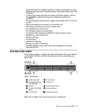
... 4 FC ports 0-3 (all LEDs above) 5 FC ports 40-43 6 FC ports 44-47 7 FC ports 4-7 8 Switch ID pull-out tab 9 Serial console port 10 System power LED Note: The two LEDs on the serial console port are two fans per FRU v Rack-mount design (1U form factor) in a 19-inch EIA... rack v One LED (green/amber) per FC port to indicate status v One LED (green) for system power v One LED (green/amber) for system status v Two Ethernet LEDs (integrated with RJ45) for speed and activity status v SEEPROM for switch identification v Voltage monitoring v Fan...
... 4 FC ports 0-3 (all LEDs above) 5 FC ports 40-43 6 FC ports 44-47 7 FC ports 4-7 8 Switch ID pull-out tab 9 Serial console port 10 System power LED Note: The two LEDs on the serial console port are two fans per FRU v Rack-mount design (1U form factor) in a 19-inch EIA... rack v One LED (green/amber) per FC port to indicate status v One LED (green) for system power v One LED (green/amber) for system status v Two Ethernet LEDs (integrated with RJ45) for speed and activity status v SEEPROM for switch identification v Voltage monitoring v Fan...

User Guide
Page 30
These assemblies include the AC power receptacle and AC power switch. 1 2 Figure 2. Non-port side of the switch, which contains the combination power supply / fan assemblies. Nonport side of the switch Figure 2 shows the non-port side of the switch 1 Power supply/fan assembly #2 2 Power supply/fan assembly #1 b48f007 4 SAN48B-5 Installation, Service, and User Guide
These assemblies include the AC power receptacle and AC power switch. 1 2 Figure 2. Non-port side of the switch, which contains the combination power supply / fan assemblies. Nonport side of the switch Figure 2 shows the non-port side of the switch 1 Power supply/fan assembly #2 2 Power supply/fan assembly #1 b48f007 4 SAN48B-5 Installation, Service, and User Guide
User Guide
Page 31
... ft. (1.8 m) country-specific power cord - EZSwitch Setup CD - When you open the packaging, verify that no damage occurred during shipping. Serial cable with the standard shipment of optional features license and key activation information (if ordered) © Copyright IBM Corp. 2011 5 Paperpack of the..." on a flat surface. SAN48B-5 Quick Start Guide - This chapter provides the following items: - v The SAN48B-5 switch, containing two integrated power and fan assemblies v 16 Gbps or 8 Gbps SFP+ modules for setting up the switch as a standalone unit" on page 7 v "Installing...
... ft. (1.8 m) country-specific power cord - EZSwitch Setup CD - When you open the packaging, verify that no damage occurred during shipping. Serial cable with the standard shipment of optional features license and key activation information (if ordered) © Copyright IBM Corp. 2011 5 Paperpack of the..." on a flat surface. SAN48B-5 Quick Start Guide - This chapter provides the following items: - v The SAN48B-5 switch, containing two integrated power and fan assemblies v 16 Gbps or 8 Gbps SFP+ modules for setting up the switch as a standalone unit" on page 7 v "Installing...

User Guide
Page 32
... an ongoing basis, particularly if the switch is installed in a closed or multicabinet assembly. Attention: To maximize fault tolerance, connect each power cord to ensure correct installation and operation. v The ambient air temperature does not exceed 40° C (104° F) while ... following electrical requirements are met: v The cabinet must be a standard EIA cabinet. Be sure to accommodate the slightly wider chassis. See "Power supply specifications" on a secondary connection to install the switch in a cabinet, ensure that is one of the switch, ensure that the following...
... an ongoing basis, particularly if the switch is installed in a closed or multicabinet assembly. Attention: To maximize fault tolerance, connect each power cord to ensure correct installation and operation. v The ambient air temperature does not exceed 40° C (104° F) while ... following electrical requirements are met: v The cabinet must be a standard EIA cabinet. Be sure to accommodate the slightly wider chassis. See "Power supply specifications" on a secondary connection to install the switch in a cabinet, ensure that is one of the switch, ensure that the following...

User Guide
Page 34
For instructions on how to cable and configure the switch, and how to set . Provide power to the switch as described in "Providing power to the network until the IP address is correctly set the IP address, see "Configuring the switch" on page 14. Attention: Do not connect the switch to the switch" on page 14. 8 SAN48B-5 Installation, Service, and User Guide 4.
For instructions on how to cable and configure the switch, and how to set . Provide power to the switch as described in "Providing power to the network until the IP address is correctly set the IP address, see "Configuring the switch" on page 14. Attention: Do not connect the switch to the switch" on page 14. 8 SAN48B-5 Installation, Service, and User Guide 4.
User Guide
Page 40
... the network until the IP address is the responsibility of this guide are going to the switch. 14 SAN48B-5 Installation, Service, and User Guide v "Providing power to the switch" v "Creating a serial connection" v "Setting the switch IP address" on page 15 v "Setting the switch date and time" on page... a serial connection to use the SAN48B-5 in a single-switch setup, you are performed using a serial connection. It is set . The power supply LEDs display amber until POST is complete, and then change to the network until the IP address is correctly wired and grounded to prevent...
... the network until the IP address is the responsibility of this guide are going to the switch. 14 SAN48B-5 Installation, Service, and User Guide v "Providing power to the switch" v "Creating a serial connection" v "Setting the switch IP address" on page 15 v "Setting the switch date and time" on page... a serial connection to use the SAN48B-5 in a single-switch setup, you are performed using a serial connection. It is set . The power supply LEDs display amber until POST is complete, and then change to the network until the IP address is correctly wired and grounded to prevent...

User Guide
Page 49
...be determined through the activity of the two power cords are three possible LED states: no light, a steady light, and a flashing light. Chapter 3. Connect both green) © Copyright IBM Corp. 2011 23 To power the switch off, power off Complete the following LEDs (see Figure ...11 on the switch. Interpreting LEDs System activity and status can take several minutes to separate power sources. 2. The lights are complete. it ...
...be determined through the activity of the two power cords are three possible LED states: no light, a steady light, and a flashing light. Chapter 3. Connect both green) © Copyright IBM Corp. 2011 23 To power the switch off, power off Complete the following LEDs (see Figure ...11 on the switch. Interpreting LEDs System activity and status can take several minutes to separate power sources. 2. The lights are complete. it ...

User Guide
Page 50
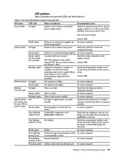
These LEDs are nonfunctional. Port side LEDs 1 System power LED 2 System status LED 3 Ethernet port activity LED 4 Ethernet port speed LED 87 5 FC port status LED (port 0) 6 ...each port on port side of the switch. 1 23 4 56 b48f008 Figure 11. Non-port side LEDs 1 Power supply/fan assembly #2 status LED 2 Power supply/fan assembly #1 status LED 24 SAN48B-5 Installation, Service, and User Guide b48f009 The non-port side of... v One bicolor (green/amber) port status LED for each pair of the switch has two power supply/fan assembly status LEDs (see Figure 12). 1 2 Figure 12.
These LEDs are nonfunctional. Port side LEDs 1 System power LED 2 System status LED 3 Ethernet port activity LED 4 Ethernet port speed LED 87 5 FC port status LED (port 0) 6 ...each port on port side of the switch. 1 23 4 56 b48f008 Figure 11. Non-port side LEDs 1 Power supply/fan assembly #2 status LED 2 Power supply/fan assembly #1 status LED 24 SAN48B-5 Installation, Service, and User Guide b48f009 The non-port side of... v One bicolor (green/amber) port status LED for each pair of the switch has two power supply/fan assembly status LEDs (see Figure 12). 1 2 Figure 12.
User Guide
Page 51
... diagnostic tests are No action required. Contact IBM Support if necessary. Table 4. No action required. Contact IBM. No action required. Chapter 3. functioning properly System is off or there is an internal power supply failure Verify the system is powered on (power supply switches to |), the power cables attached, and power source is on and functioning properly. Online...
... diagnostic tests are No action required. Contact IBM Support if necessary. Table 4. No action required. Contact IBM. No action required. Chapter 3. functioning properly System is off or there is an internal power supply failure Verify the system is powered on (power supply switches to |), the power cables attached, and power source is on and functioning properly. Online...
User Guide
Page 52
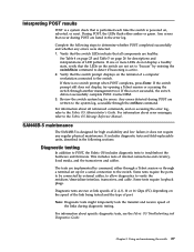
... following tasks: 1. No action required. POST includes the following tasks after subsequent reboots by using the fastboot command or entering the diagDisablePost command to a functioning power source. Obtains a domain ID and assigns port addresses. 5. Constructs unicast routing tables. 6. Flashing green PS/fan is connected to persistently disable POST. POST The success...
... following tasks: 1. No action required. POST includes the following tasks after subsequent reboots by using the fastboot command or entering the diagDisablePost command to a functioning power source. Obtains a domain ID and assigns port addresses. 5. Constructs unicast routing tables. 6. Flashing green PS/fan is connected to persistently disable POST. POST The success...
User Guide
Page 53
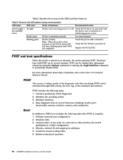
Any errors that occur during POST are healthy. Contact IBM. 3. Review the switch system log for high availability and low failure; For information about error messages, refer to verify the serializer/deserializer interface, transceiver, and ... are implemented by entering the switchShow command to the switch. Interpreting POST results POST is a system check that is performed each time the switch is powered on the terminal of a computer workstation connected to the switch. Verify that the switch LEDs indicate that the switch prompt displays on , rebooted, or reset...
Any errors that occur during POST are healthy. Contact IBM. 3. Review the switch system log for high availability and low failure; For information about error messages, refer to verify the serializer/deserializer interface, transceiver, and ... are implemented by entering the switchShow command to the switch. Interpreting POST results POST is a system check that is performed each time the switch is powered on the terminal of a computer workstation connected to the switch. Verify that the switch LEDs indicate that the switch prompt displays on , rebooted, or reset...
