

User Guide
Page 11
... Gbps SFP+ with wire bail latch 20 10. Installing a cable 20 11. Port side LEDs 24 12. Removing the power supply and fan assembly 32 16. Location of the switch 4 3. Attach the rear bracket ... rail rack mount kit . . . . 10 4. Non-port side of battery holder 34 © Copyright IBM Corp. 2011 ix Figures 1. Port side view 3 2. Position the rear and front brackets . . . . 12 7. Non-port side LEDs 24 13. Exhaust airflow label 29 14. Switch power supply and fan assemblies on the non-port side 30...
... Gbps SFP+ with wire bail latch 20 10. Installing a cable 20 11. Port side LEDs 24 12. Removing the power supply and fan assembly 32 16. Location of the switch 4 3. Attach the rear bracket ... rail rack mount kit . . . . 10 4. Non-port side of battery holder 34 © Copyright IBM Corp. 2011 ix Figures 1. Port side view 3 2. Position the rear and front brackets . . . . 12 7. Non-port side LEDs 24 13. Exhaust airflow label 29 14. Switch power supply and fan assemblies on the non-port side 30...
User Guide
Page 32
... equipment in the rack should force air in a safe place. v Airflow and temperature requirements are slimmer than standard rails to accommodate the slightly wider chassis. Environmental requirements For successful installation and operation of the switch, ensure that the following cabinet requirements are ...are met on a secondary connection to a branch circuit, such as specified by a circuit breaker, and grounded in the cabinet is installed in a closed or multicabinet assembly. Do not rely on an ongoing basis, particularly if the switch is grounded through a reliable branch...
... equipment in the rack should force air in a safe place. v Airflow and temperature requirements are slimmer than standard rails to accommodate the slightly wider chassis. Environmental requirements For successful installation and operation of the switch, ensure that the following cabinet requirements are ...are met on a secondary connection to a branch circuit, such as specified by a circuit breaker, and grounded in the cabinet is installed in a closed or multicabinet assembly. Do not rely on an ongoing basis, particularly if the switch is grounded through a reliable branch...
User Guide
Page 55
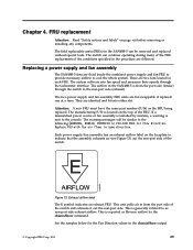
.... The manufacturing P/N is generally referred to cool the whole system. If a mismatched power source or fan assembly is installed by the chassisShow command. E nety008 AIRFLOW Figure 13. This unit pulls air in the procedure are followed. See the samples below for the Fan Direction values ...airflow in each FRU. The warning messages will be removed and replaced without special tools. The switch can be similar to the console. The field replaceable units (FRUs) in PSU-FAN FRUS Air Flow direction. Replace PSU with fan air flows in the chassisShow output © Copyright IBM...
.... The manufacturing P/N is generally referred to cool the whole system. If a mismatched power source or fan assembly is installed by the chassisShow command. E nety008 AIRFLOW Figure 13. This unit pulls air in the procedure are followed. See the samples below for the Fan Direction values ...airflow in each FRU. The warning messages will be removed and replaced without special tools. The switch can be similar to the console. The field replaceable units (FRUs) in PSU-FAN FRUS Air Flow direction. Replace PSU with fan air flows in the chassisShow output © Copyright IBM...

User Guide
Page 56
Switch power supply and fan assemblies on and seated and the power cord is on the non-port side 1 Power supply/fan assembly #2 2 Airflow label 3 Power supply/fan assembly #1 4 On/off . Maintain both power supply and fan assembly in the switch until it can be replaced. Verify ...that the power supply and fan assembly is connected to a functioning power source. 30 SAN48B-5 Installation, Service, and User Guide Fabric OS identifies the assemblies from this illustration but the locations are no user-serviceable parts inside the power supply and...
Switch power supply and fan assemblies on and seated and the power cord is on the non-port side 1 Power supply/fan assembly #2 2 Airflow label 3 Power supply/fan assembly #1 4 On/off . Maintain both power supply and fan assembly in the switch until it can be replaced. Verify ...that the power supply and fan assembly is connected to a functioning power source. 30 SAN48B-5 Installation, Service, and User Guide Fabric OS identifies the assemblies from this illustration but the locations are no user-serviceable parts inside the power supply and...

User Guide
Page 58
... to the O symbol. Unplug the power cord from the switch. 1. Remove the power supply and fan assembly 2 from the chassis 1 . 6. Note the part number and airflow label 4 on for this procedure. To leave the switch in the other power supply and fan assembly (the one not being replaced. 4. Power off the... out and away from the chassis by pressing the AC power switch to replace a combined power supply and fan assembly in the switch 32 SAN48B-5 Installation, Service, and User Guide
... to the O symbol. Unplug the power cord from the switch. 1. Remove the power supply and fan assembly 2 from the chassis 1 . 6. Note the part number and airflow label 4 on for this procedure. To leave the switch in the other power supply and fan assembly (the one not being replaced. 4. Power off the... out and away from the chassis by pressing the AC power switch to replace a combined power supply and fan assembly in the switch 32 SAN48B-5 Installation, Service, and User Guide

User Guide
Page 59
...Ensure that the power supply is not a steady green, ensure that the new power supply and fan assembly has the same part number and airflow label as instructed by tightening in easily, ensure that the LED on the unit by pressing the AC power switch to display the status.... not slide in the captive screw 3 . 2. Disconnect all transceivers. 3. Chapter 4. If the LED is securely installed and seated properly. 4. Orient the new power supply and fan assembly with the IBM-approved part. Complete these steps to the B1 location ( 1 in Figure 16 on the right, as shown in...
...Ensure that the power supply is not a steady green, ensure that the new power supply and fan assembly has the same part number and airflow label as instructed by tightening in easily, ensure that the LED on the unit by pressing the AC power switch to display the status.... not slide in the captive screw 3 . 2. Disconnect all transceivers. 3. Chapter 4. If the LED is securely installed and seated properly. 4. Orient the new power supply and fan assembly with the IBM-approved part. Complete these steps to the B1 location ( 1 in Figure 16 on the right, as shown in...