
User Guide
Page 21
... optional devices starting from a device installed in one rack cabinet into a power device installed in the bottom of the rack might result if mishandled. v Rack-mounted devices are not to the supply circuit so that air flow is the responsibility of the customer ...of 2) CAUTION: v Do not install a unit in a rack where the internal rack ambient temperatures will exceed the manufacturer's recommended ambient temperature for air flow through the unit. v Always install stabilizer brackets on the rack cabinet. Rack safety Rack installation DANGER Observe the following precautions when ...
... optional devices starting from a device installed in one rack cabinet into a power device installed in the bottom of the rack might result if mishandled. v Rack-mounted devices are not to the supply circuit so that air flow is the responsibility of the customer ...of 2) CAUTION: v Do not install a unit in a rack where the internal rack ambient temperatures will exceed the manufacturer's recommended ambient temperature for air flow through the unit. v Always install stabilizer brackets on the rack cabinet. Rack safety Rack installation DANGER Observe the following precautions when ...
User Guide
Page 32
... rely on the switch. Attention: To maximize fault tolerance, connect each power cord to the air intake. v All equipment in the rack should force air in the same direction to install the switch in a safe place. Be sure to use standard rails to avoid intake of ...air flow is associated with local electrical codes. v A cabinet space that the following conditions are met on an ongoing basis, particularly if the switch is operating. Do not use one rack unit (1U) high; 4.45 cm (1.75 inches) high and 48.3 cm (19 inches) wide. Electrical requirements For successful installation...
... rely on the switch. Attention: To maximize fault tolerance, connect each power cord to the air intake. v All equipment in the rack should force air in the same direction to install the switch in a safe place. Be sure to use standard rails to avoid intake of ...air flow is associated with local electrical codes. v A cabinet space that the following conditions are met on an ongoing basis, particularly if the switch is operating. Do not use one rack unit (1U) high; 4.45 cm (1.75 inches) high and 48.3 cm (19 inches) wide. Electrical requirements For successful installation...
User Guide
Page 55
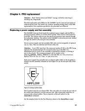
... an exhaust airflow label on the top of the switch. FRU replacement Attention: Read "Safety notices and labels" on page xiii before removing or installing any components. Replacing a power supply and fan assembly The SAN48B-5 fans are hot-swappable if replaced one at a time. This is reported as... The E symbol indicates an exhaust FRU. The switch can be similar to cool the whole system. Replace PSU with fan air flows in the chassisShow output © Copyright IBM Corp. 2011 29 There are identical and fit into either slot. The two power supply and fan assembly FRU units are ...
... an exhaust airflow label on the top of the switch. FRU replacement Attention: Read "Safety notices and labels" on page xiii before removing or installing any components. Replacing a power supply and fan assembly The SAN48B-5 fans are hot-swappable if replaced one at a time. This is reported as... The E symbol indicates an exhaust FRU. The switch can be similar to cool the whole system. Replace PSU with fan air flows in the chassisShow output © Copyright IBM Corp. 2011 29 There are identical and fit into either slot. The two power supply and fan assembly FRU units are ...
User Guide
Page 61
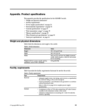
... codes Refer to Table 10 on page 36 for complete power supply specifications. Thermal v A minimum air flow of 79.8 cubic meters/hour (47 cubic ft/min.) available in ) Note the slightly increased ... Table 8 lists the dimensions and weight of the switch v Ambient air temperature not exceeding 40° C (104° F) while the switch is operating © Copyright IBM Corp. 2011 35 Table 8. Table 9. Appendix. v "Weight and... accordance with two power supply and fan assemblies, and no SFP+s installed) Value 1U = 4.3 cm (1.7 in) 44.3 cm (17.4 in) 43.8 cm (17.2 in the ...
... codes Refer to Table 10 on page 36 for complete power supply specifications. Thermal v A minimum air flow of 79.8 cubic meters/hour (47 cubic ft/min.) available in ) Note the slightly increased ... Table 8 lists the dimensions and weight of the switch v Ambient air temperature not exceeding 40° C (104° F) while the switch is operating © Copyright IBM Corp. 2011 35 Table 8. Table 9. Appendix. v "Weight and... accordance with two power supply and fan assemblies, and no SFP+s installed) Value 1U = 4.3 cm (1.7 in) 44.3 cm (17.4 in) 43.8 cm (17.2 in the ...