

User Guide
Page 9
... replacement . . . . . 29 Replacing a power supply and fan assembly . . . 29 Determining the need to the switch 14 © Copyright IBM Corp. 2011 Creating a serial connection 14 Setting the switch IP address 15 Setting the switch date and time 16 Inter-Switch Link (ISL) Trunking 19 Installing SFP+ transceivers and connecting cables 19 Fabric OS Native and...
... replacement . . . . . 29 Replacing a power supply and fan assembly . . . 29 Determining the need to the switch 14 © Copyright IBM Corp. 2011 Creating a serial connection 14 Setting the switch IP address 15 Setting the switch date and time 16 Inter-Switch Link (ISL) Trunking 19 Installing SFP+ transceivers and connecting cables 19 Fabric OS Native and...

User Guide
Page 11
...power supply and fan assembly 32 16. Port side view 3 2. Items in the cabinet . . . . . 12 6. Location of the switch 4 3. Figures 1. Position the switch in the slim rail rack mount kit . . . . 10 4. Position the rear and front brackets . . . . 12 7. Installing a cable 20 11.... Switch power supply and fan assemblies on the non-port side 30 15. Non-port side of battery holder 34 © Copyright IBM Corp. 2011 ix Attach the rear bracket to the cabinet rail 13 8. Exhaust airflow label...
...power supply and fan assembly 32 16. Port side view 3 2. Items in the cabinet . . . . . 12 6. Location of the switch 4 3. Figures 1. Position the switch in the slim rail rack mount kit . . . . 10 4. Position the rear and front brackets . . . . 12 7. Installing a cable 20 11.... Switch power supply and fan assemblies on the non-port side 30 15. Non-port side of battery holder 34 © Copyright IBM Corp. 2011 ix Attach the rear bracket to the cabinet rail 13 8. Exhaust airflow label...

User Guide
Page 13
...side LED patterns during normal operation 25 5. Power supply and fan assembly status LED behavior 30 8. Switch dimensions 35 9. General specifications 37 13. Tables 1. Brocade and IBM product and model number matrix xxiv 3. Facility requirements 35 10. Supported optics, speeds, cables, ... Management options for slim rail rack mount kit . . . . 9 4. Access Gateway default port mapping . . . 40 © Copyright IBM Corp. 2011 xi Parts list for the SAN48B-5 28 7. Port side LED patterns during normal operation 26 6. Serial cable pinouts 39 16. Power...
...side LED patterns during normal operation 25 5. Power supply and fan assembly status LED behavior 30 8. Switch dimensions 35 9. General specifications 37 13. Tables 1. Brocade and IBM product and model number matrix xxiv 3. Facility requirements 35 10. Supported optics, speeds, cables, ... Management options for slim rail rack mount kit . . . . 9 4. Access Gateway default port mapping . . . 40 © Copyright IBM Corp. 2011 xi Parts list for the SAN48B-5 28 7. Port side LED patterns during normal operation 26 6. Serial cable pinouts 39 16. Power...
User Guide
Page 15
...situations that can be potentially lethal or extremely hazardous to locate the translation of these danger and caution notices in the IBM System Storage b-type Switch and Router Safety Notices publication, which are listed below in this device. v In addition to these situations. Read ...to a situation that follow. A lightning bolt symbol accompanies a danger notice to warn of the danger, caution, and attention notices in IBM documents. DANGER To prevent a possible shock from touching two surfaces with the following notices and statements are also attached directly to products to...
...situations that can be potentially lethal or extremely hazardous to locate the translation of these danger and caution notices in the IBM System Storage b-type Switch and Router Safety Notices publication, which are listed below in this device. v In addition to these situations. Read ...to a situation that follow. A lightning bolt symbol accompanies a danger notice to warn of the danger, caution, and attention notices in IBM documents. DANGER To prevent a possible shock from touching two surfaces with the following notices and statements are also attached directly to products to...
User Guide
Page 25
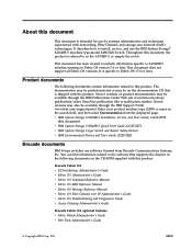
...'s Guide © Copyright IBM Corp. 2011 xxiii About this document) v IBM System Storage SAN48B-5 Quick Start Guide, GC27-2271 v IBM System Storage b-type Switch and Router Safety Notices v IBM Environmental Notices and User Guide, Z125-5823 Brocade documents IBM b-type switches use software licensed from the displayed page. Enter your product machine type (2498) or name in the...
...'s Guide © Copyright IBM Corp. 2011 xxiii About this document) v IBM System Storage SAN48B-5 Quick Start Guide, GC27-2271 v IBM System Storage b-type Switch and Router Safety Notices v IBM Environmental Notices and User Guide, Z125-5823 Brocade documents IBM b-type switches use software licensed from the displayed page. Enter your product machine type (2498) or name in the...

User Guide
Page 26
... DCX-4S Brocade DCX Brocade Encryption Switch Brocade 8000 Brocade 7800 Brocade 5300 Brocade 5100 Brocade 300 IBM product name SAN48B-5 SAN384B-2 SAN768B-2 SAN384B SAN768B SAN32B-E4 IBM Converged Switch B32 SAN06B-R SAN80B-4 SAN40B-4 SAN24B-4 IBM machine type and model number 2498 Model F48 2499 Model 416 2499... Model 816 2499 Model 192 2499 Model 384 2498 Model E32 3758 Models B32 and L32 2498 Model R06 2498 Model B80 2498 Models B40 and 40E 2498 Models ...
... DCX-4S Brocade DCX Brocade Encryption Switch Brocade 8000 Brocade 7800 Brocade 5300 Brocade 5100 Brocade 300 IBM product name SAN48B-5 SAN384B-2 SAN768B-2 SAN384B SAN768B SAN32B-E4 IBM Converged Switch B32 SAN06B-R SAN80B-4 SAN40B-4 SAN24B-4 IBM machine type and model number 2498 Model F48 2499 Model 416 2499... Model 816 2499 Model 192 2499 Model 384 2498 Model E32 3758 Models B32 and L32 2498 Model R06 2498 Model B80 2498 Models B40 and 40E 2498 Models ...

User Guide
Page 27
... SFP+ transceivers v 10 Gbps manual set capability on the first eight ports only) © Copyright IBM Corp. 2011 1 Ports can also be used to handle additional N_Ports instead of switches. Switches in Access Gateway mode that lets you simplify configuration and management in a single domain v Ports on... to grow with the ability to medium-sized workgroups. The SAN48B-5 is an enterprise-class switch that have access to the host and the fabric. Introducing the SAN48B-5 The IBM System Storage SAN48B-5 is designed to handle the large-scale SAN requirements of an enterprise, ...
... SFP+ transceivers v 10 Gbps manual set capability on the first eight ports only) © Copyright IBM Corp. 2011 1 Ports can also be used to handle additional N_Ports instead of switches. Switches in Access Gateway mode that lets you simplify configuration and management in a single domain v Ports on... to grow with the ability to medium-sized workgroups. The SAN48B-5 is an enterprise-class switch that have access to the host and the fabric. Introducing the SAN48B-5 The IBM System Storage SAN48B-5 is designed to handle the large-scale SAN requirements of an enterprise, ...

User Guide
Page 28
...configure as E, F, M, or D ports. Hardware zoning permits or denies delivery of frames to any means whatsoever to configure the switch IP address and greatly increasing the ease of value-added applications including Advanced Web Tools and Zoning. Diagnostic Port (D-Port) feature ...troubleshooting and verification services v In-flight data compression and encryption on up to eight ports (at the port level of the switch and by any destination port address v Extensive diagnostics and system-monitoring capabilities for enhanced high Reliability, Availability, and Serviceability (RAS...
...configure as E, F, M, or D ports. Hardware zoning permits or denies delivery of frames to any means whatsoever to configure the switch IP address and greatly increasing the ease of value-added applications including Advanced Web Tools and Zoning. Diagnostic Port (D-Port) feature ...troubleshooting and verification services v In-flight data compression and encryption on up to eight ports (at the port level of the switch and by any destination port address v Extensive diagnostics and system-monitoring capabilities for enhanced high Reliability, Availability, and Serviceability (RAS...
User Guide
Page 29
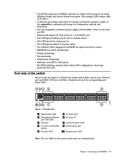
... 123 4 5 b48f006 10 9 8 7 6 Figure 1. Introducing the SAN48B-5 3 v One RS-232 serial port with RJ45 connector for initial switch setup (if not using EZSwitch Setup) and factory default restoration. (The integral LEDs remain unlit at all LEDs above) 5 FC ports 40-43 ...system power v One LED (green/amber) for system status v Two Ethernet LEDs (integrated with RJ45) for speed and activity status v SEEPROM for switch identification v Voltage monitoring v Fan monitoring v Temperature monitoring v Real-time clock (RTC) with battery v The EZSwitchSetup wizard, which makes SAN configuration...
... 123 4 5 b48f006 10 9 8 7 6 Figure 1. Introducing the SAN48B-5 3 v One RS-232 serial port with RJ45 connector for initial switch setup (if not using EZSwitch Setup) and factory default restoration. (The integral LEDs remain unlit at all LEDs above) 5 FC ports 40-43 ...system power v One LED (green/amber) for system status v Two Ethernet LEDs (integrated with RJ45) for speed and activity status v SEEPROM for switch identification v Voltage monitoring v Fan monitoring v Temperature monitoring v Real-time clock (RTC) with battery v The EZSwitchSetup wizard, which makes SAN configuration...

User Guide
Page 30
Non-port side of the switch, which contains the combination power supply / fan assemblies. These assemblies include the AC power receptacle and AC power switch. 1 2 Figure 2. Nonport side of the switch Figure 2 shows the non-port side of the switch 1 Power supply/fan assembly #2 2 Power supply/fan assembly #1 b48f007 4 SAN48B-5 Installation, Service, and User Guide
Non-port side of the switch, which contains the combination power supply / fan assemblies. These assemblies include the AC power receptacle and AC power switch. 1 2 Figure 2. Nonport side of the switch Figure 2 shows the non-port side of the switch 1 Power supply/fan assembly #2 2 Power supply/fan assembly #1 b48f007 4 SAN48B-5 Installation, Service, and User Guide
User Guide
Page 31
... are damaged or missing, within the United States and Canada, contact the IBM Quality Hotline toll-free 1-800-442-6773 or direct dial in an EIA cabinet" on page 9 v "Configuring the switch" on page 14 Attention: Read the "Safety notices and labels" on ... cable with the standard shipment of optional features license and key activation information (if ordered) © Copyright IBM Corp. 2011 5 Warranty - Chapter 2. Safety notices - EZSwitch Setup CD - Paperpack of the switch. SAN48B-5 Installation, Service, and User Guide (this document). - SAN48B-5 Quick Start Guide - Note:...
... are damaged or missing, within the United States and Canada, contact the IBM Quality Hotline toll-free 1-800-442-6773 or direct dial in an EIA cabinet" on page 9 v "Configuring the switch" on page 14 Attention: Read the "Safety notices and labels" on ... cable with the standard shipment of optional features license and key activation information (if ordered) © Copyright IBM Corp. 2011 5 Warranty - Chapter 2. Safety notices - EZSwitch Setup CD - Paperpack of the switch. SAN48B-5 Installation, Service, and User Guide (this document). - SAN48B-5 Quick Start Guide - Note:...
User Guide
Page 32
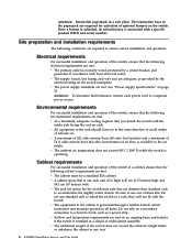
... with the intake side facing the cool-air aisle. v The ambient air temperature does not exceed 40° C (104° F) while the switch is grounded through a reliable branch circuit connection and maintain ground at all times. Do not use one rack unit (1U) high; 4.45 cm ...use standard rails to accommodate the slightly wider chassis. v The additional weight of optional features on the switch. v A cabinet space that are required for the switch uses rails that is associated with the switch. v The equipment in a rack, they will not fit with a specific product WWN and serial ...
... with the intake side facing the cool-air aisle. v The ambient air temperature does not exceed 40° C (104° F) while the switch is grounded through a reliable branch circuit connection and maintain ground at all times. Do not use one rack unit (1U) high; 4.45 cm ...use standard rails to accommodate the slightly wider chassis. v The additional weight of optional features on the switch. v A cabinet space that are required for the switch uses rails that is associated with the switch. v The equipment in a rack, they will not fit with a specific product WWN and serial ...
User Guide
Page 33
...such as a standalone unit, use tie wraps with optical cables; This provides room to remove and replace the switch, allows for backing up the switch configuration (optional) Setting up the switch as an earthquake. v Use hook and loop style straps to "Safety notices and labels" on page 5 are... for each one, and firmly press into place. Following is 2 inches under full tensile load and 1.2 inches with the switch" on page xiii before installing the switch. Do not use the following items are connected. Chapter 2. v The cabinet is secured to ensure stability in each port cable...
...such as a standalone unit, use tie wraps with optical cables; This provides room to remove and replace the switch, allows for backing up the switch configuration (optional) Setting up the switch as an earthquake. v Use hook and loop style straps to "Safety notices and labels" on page 5 are... for each one, and firmly press into place. Following is 2 inches under full tensile load and 1.2 inches with the switch" on page xiii before installing the switch. Do not use the following items are connected. Chapter 2. v The cabinet is secured to ensure stability in each port cable...

User Guide
Page 34
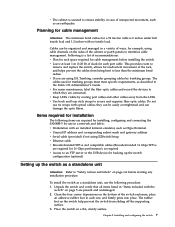
For instructions on how to cable and configure the switch, and how to the switch" on page 14. 8 SAN48B-5 Installation, Service, and User Guide Provide power to the switch as described in "Providing power to set . Attention: Do not connect the switch to the network until the IP address is correctly set the IP address, see "Configuring the switch" on page 14. 4.
For instructions on how to cable and configure the switch, and how to the switch" on page 14. 8 SAN48B-5 Installation, Service, and User Guide Provide power to the switch as described in "Providing power to set . Attention: Do not connect the switch to the network until the IP address is correctly set the IP address, see "Configuring the switch" on page 14. 4.

User Guide
Page 35
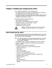
... in-lb, 10 cm-kg) 8 Screw, 10-32 x 5/8 in., panhead Phillips (torque to install the switch using the slim rail rack mount kit: v Clamps or other means of temporarily supporting the switch in the cabinet v Phillips #2 screwdriver v 1/4 in. Make sure that the items listed in Table 3 and illustrated... in Figure 3 on page 10 are listed in Table 3. Parts list for use with the switch chassis. Installing and configuring the switch 9 can damage the switch. Table 3. Items required You need the following items to 25 in-lb, 29 8 cm-kg) Retainer nut, 10-...
... in-lb, 10 cm-kg) 8 Screw, 10-32 x 5/8 in., panhead Phillips (torque to install the switch using the slim rail rack mount kit: v Clamps or other means of temporarily supporting the switch in the cabinet v Phillips #2 screwdriver v 1/4 in. Make sure that the items listed in Table 3 and illustrated... in Figure 3 on page 10 are listed in Table 3. Parts list for use with the switch chassis. Installing and configuring the switch 9 can damage the switch. Table 3. Items required You need the following items to 25 in-lb, 29 8 cm-kg) Retainer nut, 10-...

User Guide
Page 36
... shown in a slide-rail rack that meets EIA standards, use the following steps to attach the front brackets to install the switch in the bracket and then into one of the pairs of holes on page 11 3. "Attaching the rear brackets to the cabinet rails" on page ...13 Attaching the front brackets to the switch Complete the following procedure. "Attaching the front brackets to the front brackets" on page 11. 2. "Attaching the rear brackets to the...
... shown in a slide-rail rack that meets EIA standards, use the following steps to attach the front brackets to install the switch in the bracket and then into one of the pairs of holes on page 11 3. "Attaching the rear brackets to the cabinet rails" on page ...13 Attaching the front brackets to the switch Complete the following procedure. "Attaching the front brackets to the front brackets" on page 11. 2. "Attaching the rear brackets to the...
User Guide
Page 37
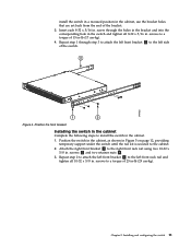
... all 8-32 x 5/16 in. Repeat step 1 through the holes in the bracket and into the corresponding hole in the switch and tighten all 10-32 x 5/8 in. Position the front bracket Installing the switch in the cabinet Complete the following steps to the cabinet. 2. screws to the left side of 15 in-lb... the cabinet, as shown in Figure 5 on page 12, providing temporary support under the switch until the rail kit is secured to install the switch in the cabinet. 1. install the switch in a recessed position in the cabinet, use the bracket holes that are set back from the end of 25 in-lb (...
... all 8-32 x 5/16 in. Repeat step 1 through the holes in the bracket and into the corresponding hole in the switch and tighten all 10-32 x 5/8 in. Position the front bracket Installing the switch in the cabinet Complete the following steps to the cabinet. 2. screws to the left side of 15 in-lb... the cabinet, as shown in Figure 5 on page 12, providing temporary support under the switch until the rail kit is secured to install the switch in the cabinet. 1. install the switch in a recessed position in the cabinet, use the bracket holes that are set back from the end of 25 in-lb (...

User Guide
Page 38
... rear and front brackets 12 SAN48B-5 Installation, Service, and User Guide 2 1 Repeat step 1 through step 3 to attach the left front bracket. 3 4 b48f004 Figure 6. Position the switch in . Position the right rear bracket 2 inside the right front bracket 1 , as shown in -lb (10 cm-kg). 4. 2 1 b48f003 3 4 Figure 5.
... rear and front brackets 12 SAN48B-5 Installation, Service, and User Guide 2 1 Repeat step 1 through step 3 to attach the left front bracket. 3 4 b48f004 Figure 6. Position the switch in . Position the right rear bracket 2 inside the right front bracket 1 , as shown in -lb (10 cm-kg). 4. 2 1 b48f003 3 4 Figure 5.

User Guide
Page 39
Installing and configuring the switch 13 screws 4 and two retainer nuts 3 , as shown in . Repeat step 1 to attach the left rear bracket to the left rear cabinet rail and tighten all the 10-32 x 5/8 in Figure 7. 2. screws to the right rear cabinet rail using two 10-32 x 5/8 in -lb (29 cm-kg). 4 3 2 1 Figure 7. b48f005 Attaching the rear brackets to the cabinet rails Complete the following steps to attach the rear brackets to the cabinet rail Chapter 2. Attach the rear bracket to the cabinet rails. 1. Attach the right rear bracket 2 to a torque of 25 in .
Installing and configuring the switch 13 screws 4 and two retainer nuts 3 , as shown in . Repeat step 1 to attach the left rear bracket to the left rear cabinet rail and tighten all the 10-32 x 5/8 in Figure 7. 2. screws to the right rear cabinet rail using two 10-32 x 5/8 in -lb (29 cm-kg). 4 3 2 1 Figure 7. b48f005 Attaching the rear brackets to the cabinet rails Complete the following steps to attach the rear brackets to the cabinet rail Chapter 2. Attach the rear bracket to the cabinet rails. 1. Attach the right rear bracket 2 to a torque of 25 in .
User Guide
Page 40
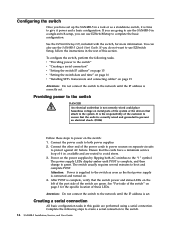
...the IP address is correctly wired and grounded to the "|" symbol. See the EZSwitchSetup CD, included with the switch, for the specific location of these steps to the switch. 14 SAN48B-5 Installation, Service, and User Guide available and are performed using a serial connection. Creating a serial... connection All basic configuration tasks in the rest of the system or the devices that the outlet is correctly set . The switch usually requires several minutes to the network until the IP address is the responsibility of the power cords to power sources on page ...
...the IP address is correctly wired and grounded to the "|" symbol. See the EZSwitchSetup CD, included with the switch, for the specific location of these steps to the switch. 14 SAN48B-5 Installation, Service, and User Guide available and are performed using a serial connection. Creating a serial... connection All basic configuration tasks in the rest of the system or the devices that the outlet is correctly set . The switch usually requires several minutes to the network until the IP address is the responsibility of the power cords to power sources on page ...
