Owners Manual
Page 2
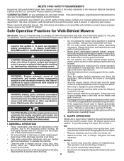
... other engine parts become • Always wear safety goggles or safety glasses with the controls and the proper caution. extremely hot during operation and remain hot after handling. •... never up and thrown by the manufacturer. • Stop the blade(s) when crossing gravel drives, walks, or roads. The operator could cause slipping. 2 Should you experience any problem ...to operate the machine. • Clear the area of accessories. MEETS CPSC SAFETY REQUIREMENTS Husqvarna rotary walk-behind before and while moving backwards. • Never direct discharged material toward ...
... other engine parts become • Always wear safety goggles or safety glasses with the controls and the proper caution. extremely hot during operation and remain hot after handling. •... never up and thrown by the manufacturer. • Stop the blade(s) when crossing gravel drives, walks, or roads. The operator could cause slipping. 2 Should you experience any problem ...to operate the machine. • Clear the area of accessories. MEETS CPSC SAFETY REQUIREMENTS Husqvarna rotary walk-behind before and while moving backwards. • Never direct discharged material toward ...
Owners Manual
Page 6
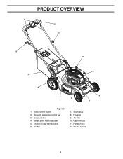
Muffler 7. Gas filler cap 11. Engine oil cap with dipstick 6. Grass catcher 4. Starter handle 6 Drive control levers 2. Spark plug 8. Operator presence control bar 3. Housing 9. PRODUCT OVERVIEW 1 2 11 12 10 9 3 4 5 6 8 7 Figure 5 1. Single point height adjuster 5. Handle knob 12. Air filter 10.
Muffler 7. Gas filler cap 11. Engine oil cap with dipstick 6. Grass catcher 4. Starter handle 6 Drive control levers 2. Spark plug 8. Operator presence control bar 3. Housing 9. PRODUCT OVERVIEW 1 2 11 12 10 9 3 4 5 6 8 7 Figure 5 1. Single point height adjuster 5. Handle knob 12. Air filter 10.
Owners Manual
Page 7
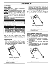
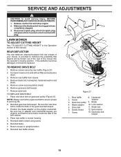
...2. OPERATION OPERATION ENGINE SPEED The engine speed was set at the factory for optimum performance. Operator presence control bar 2. Drive control levers DRIVE CONTROL ADJUSTMENT Over time, the drive control system may become "loose", resulting in the engine. 2. disconnect spark plug wire from plug. 2. ... of blade contact injury. Forward motion will stop forward motion without self-propelling (Figure 7). To stop when either drive control lever rearward to start and operate the mower. The blade turns when the engine is not adjustable. Turn unit off;...
...2. OPERATION OPERATION ENGINE SPEED The engine speed was set at the factory for optimum performance. Operator presence control bar 2. Drive control levers DRIVE CONTROL ADJUSTMENT Over time, the drive control system may become "loose", resulting in the engine. 2. disconnect spark plug wire from plug. 2. ... of blade contact injury. Forward motion will stop forward motion without self-propelling (Figure 7). To stop when either drive control lever rearward to start and operate the mower. The blade turns when the engine is not adjustable. Turn unit off;...
Owners Manual
Page 14
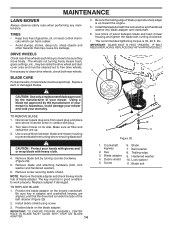
...not turning freely means trash, grass cuttings, etc., may cause tire damage. BLADE CARE For best results, mower blade must be cleaned out to free drive wheels. Replace bent or damaged blades. 4. Be sure the trailing edge of blade (opposite sharp edge) is inside the tabs of gasoline, oil,... or insect control chemicals which can harm rubber. • Avoid stumps, stones, deep ruts, sharp objects and other hazards that the drive belt is up . 3. IMPORTANT: BLADE BOLT IS HEAT TREATED. Remove blade bolt by the ...
...not turning freely means trash, grass cuttings, etc., may cause tire damage. BLADE CARE For best results, mower blade must be cleaned out to free drive wheels. Replace bent or damaged blades. 4. Be sure the trailing edge of blade (opposite sharp edge) is inside the tabs of gasoline, oil,... or insect control chemicals which can harm rubber. • Avoid stumps, stones, deep ruts, sharp objects and other hazards that the drive belt is up . 3. IMPORTANT: BLADE BOLT IS HEAT TREATED. Remove blade bolt by the ...
Owners Manual
Page 18
...Reinstall blade. 7. Hardened 2. Blade 4. Lock washer 5. Debris shield 12. Release control bar and stop engine. 2. TO REMOVE DRIVE BELT 1. Remove screw securing debris shield. 6. Be sure the new drive belt is inside the tabs of this manual. Blade bolt 6. Make sure the blade... rear wheels of your mower, is provided to upright position. 8. Remove blade bolt, lockwasher, hardened washer and blade. 5. Remove drive belt. Position the blade adapter on its side with plug. Screw Washer 3. Disconnect spark plug wire from mower. 4. Belt retainer ...
...Reinstall blade. 7. Hardened 2. Blade 4. Lock washer 5. Debris shield 12. Release control bar and stop engine. 2. TO REMOVE DRIVE BELT 1. Remove screw securing debris shield. 6. Be sure the new drive belt is inside the tabs of this manual. Blade bolt 6. Make sure the blade... rear wheels of your mower, is provided to upright position. 8. Remove blade bolt, lockwasher, hardened washer and blade. 5. Remove drive belt. Position the blade adapter on its side with plug. Screw Washer 3. Disconnect spark plug wire from mower. 4. Belt retainer ...
Owners Manual
Page 22
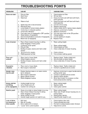
...too high or wheel height is disconnected. 5. Handle height position not right for you. 1. Empty grass catcher. 4. "Loose" drive control system. 1. Turn fuel valve lever to push 1. Connect battery to pull 1. Raise cutting height. 2. uneven 1. Buildup of ...Grass catcher 1. Catcher not venting air. 1. Loss of drive (or slowing of fuel. 2. Adjust drive control. 22 Loose blade or broken blade adapter. 7. Control bar in OFF position. 10. Engine flywheel brake is on when control bar is released. 2. Replace blade adapter. 4. Raise ...
...too high or wheel height is disconnected. 5. Handle height position not right for you. 1. Empty grass catcher. 4. "Loose" drive control system. 1. Turn fuel valve lever to push 1. Connect battery to pull 1. Raise cutting height. 2. uneven 1. Buildup of ...Grass catcher 1. Catcher not venting air. 1. Loss of drive (or slowing of fuel. 2. Adjust drive control. 22 Loose blade or broken blade adapter. 7. Control bar in OFF position. 10. Engine flywheel brake is on when control bar is released. 2. Replace blade adapter. 4. Raise ...
Owners Manual
Page 23
... dealer prior to handle warranty adjustments or repairs on ExhibitA, Transmission / Transaxle (including Drive Systems) are NOT manufactured by Husqvarna in which case they may be covered separately by a separate emission control warranty statement supplied with the product at the Husqvarna Factory. 7. Depending on Exhibit A, all Engines and Attachments are NOT covered. 23 Set...
... dealer prior to handle warranty adjustments or repairs on ExhibitA, Transmission / Transaxle (including Drive Systems) are NOT manufactured by Husqvarna in which case they may be covered separately by a separate emission control warranty statement supplied with the product at the Husqvarna Factory. 7. Depending on Exhibit A, all Engines and Attachments are NOT covered. 23 Set...
Parts List
Page 5
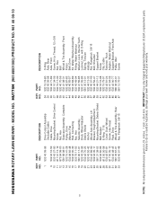
... 31 532 40 48-45 32 581 33 67-01 33 532 40 91-48 DESCRIPTION Drive Control Assembly (Includes Cable) Cable, Drive Mounting Bracket, Drive Control Screw Nut, Hex Gearcase Assembly, Complete Pulley, Drive Washer, Flat Rod, Connecting Nut, Hex Selector Assembly Knob, Wheel Adjuster Debris Shield Anchor Wheel... LH Bracket, Height Adjustment Mounting Bracket, Debris Shield Belt Keeper E-Ring 7/16 Cover, Dust, Wheel Screw, Hex Head Pawl, Drive Wheel & Tire Assembly, Rear Nut, Flangelock 3/8-16 KEY PART NO. HUSQVARNA ROTARY LAWN MOWER - HU775H (96145001000) PRODUCT NO. 961 45 00-10 KEY PART NO.
... 31 532 40 48-45 32 581 33 67-01 33 532 40 91-48 DESCRIPTION Drive Control Assembly (Includes Cable) Cable, Drive Mounting Bracket, Drive Control Screw Nut, Hex Gearcase Assembly, Complete Pulley, Drive Washer, Flat Rod, Connecting Nut, Hex Selector Assembly Knob, Wheel Adjuster Debris Shield Anchor Wheel... LH Bracket, Height Adjustment Mounting Bracket, Debris Shield Belt Keeper E-Ring 7/16 Cover, Dust, Wheel Screw, Hex Head Pawl, Drive Wheel & Tire Assembly, Rear Nut, Flangelock 3/8-16 KEY PART NO. HUSQVARNA ROTARY LAWN MOWER - HU775H (96145001000) PRODUCT NO. 961 45 00-10 KEY PART NO.


