

Owner Manual
Page 1
Operator's manual HUSQVARNA AUTOMOWER® 430XH/450XH Read the operator's manual carefully and make sure that you understand the instructions before you use the product. EN, English
Operator's manual HUSQVARNA AUTOMOWER® 430XH/450XH Read the operator's manual carefully and make sure that you understand the instructions before you use the product. EN, English

Owner Manual
Page 2
... service 39 6 Troubleshooting 6.1 Introduction - troubleshooting 40 6.2 Fault messages 40 6.3 Information messages 45 6.4 LED indicator lamp on the charging station 47 6.5 LED indicator lamp on the battery 6 1.7 Menu structure overview 1 7 1.8 Menu structure overview 2 8 1.9 Menu structure overview 3 9 1.10 Display 10 1.11 Keypad 10 2 Safety 2.1 Safety definitions 11 2.2 General safety instructions 11 2.3 Safety instructions for operation 13 3 Installation 3.1 Introduction - Start 34 4.4 Operating mode - Installation 16 3.2 Before the installation of the wires...
... service 39 6 Troubleshooting 6.1 Introduction - troubleshooting 40 6.2 Fault messages 40 6.3 Information messages 45 6.4 LED indicator lamp on the charging station 47 6.5 LED indicator lamp on the battery 6 1.7 Menu structure overview 1 7 1.8 Menu structure overview 2 8 1.9 Menu structure overview 3 9 1.10 Display 10 1.11 Keypad 10 2 Safety 2.1 Safety definitions 11 2.2 General safety instructions 11 2.3 Safety instructions for operation 13 3 Installation 3.1 Introduction - Start 34 4.4 Operating mode - Installation 16 3.2 Before the installation of the wires...

Owner Manual
Page 4
... figure represent: 1. Keypad 12. Skid plate 18. LED for securing the charging station 25. Alarm decal 27. Screws for operation check of the charging station and boundary wire 20. Low voltage cable 4 - Hatch to display and keypad 3. Headlights 8. Replaceable cover 9. Rear wheels 6. product identification code) 10. Blade disc 17. Charging station 21. Cable markers 23. Rating plate (incl. Cutting system 13. Power supply 22. Main switch 15.
... figure represent: 1. Keypad 12. Skid plate 18. LED for securing the charging station 25. Alarm decal 27. Screws for operation check of the charging station and boundary wire 20. Low voltage cable 4 - Hatch to display and keypad 3. Headlights 8. Replaceable cover 9. Rear wheels 6. product identification code) 10. Blade disc 17. Charging station 21. Cable markers 23. Rating plate (incl. Cutting system 13. Power supply 22. Main switch 15.

Owner Manual
Page 5
... product cuts the lawn. A broken seal can only start when the correct PIN code has been entered. Be careful when trimming edges where the cables are placed. 1.5 Symbols on the rating plate. The cutting height function sets the cutting height of the Installation kit which are set out in accordance with local legal requirements. The security function lets the operator select between 3 security levels. 1 Is a part...
... product cuts the lawn. A broken seal can only start when the correct PIN code has been entered. Be careful when trimming edges where the cables are placed. 1.5 Symbols on the rating plate. The cutting height function sets the cutting height of the Installation kit which are set out in accordance with local legal requirements. The security function lets the operator select between 3 security levels. 1 Is a part...

Owner Manual
Page 6
...) An X next to the bars indicates a problem with the SIM card or the module. (Automower® Connect) The product will not cut the grass do not charge the battery. The settings function is where the general settings for the accessories. The SIM symbol indicates that there is put in ECO-mode. 6 - The GPS-supported navigation is used for settings made for the products...
...) An X next to the bars indicates a problem with the SIM card or the module. (Automower® Connect) The product will not cut the grass do not charge the battery. The settings function is where the general settings for the accessories. The SIM symbol indicates that there is put in ECO-mode. 6 - The GPS-supported navigation is used for settings made for the products...

Owner Manual
Page 15
... event of a thunderstorm 2.3.4 Maintenance WARNING: When the product is turned upside down the main switch must always be set in the product and the charging station, we recommend that each week and replace any cleaning or maintenance of the charging station or the loop wire. Some models have additional guide wires (G2, G3). 2. Never use a high-pressure washer or even running water to Maintenance on the chassis...
... event of a thunderstorm 2.3.4 Maintenance WARNING: When the product is turned upside down the main switch must always be set in the product and the charging station, we recommend that each week and replace any cleaning or maintenance of the charging station or the loop wire. Some models have additional guide wires (G2, G3). 2. Never use a high-pressure washer or even running water to Maintenance on the chassis...

Owner Manual
Page 20
... understand the instructions about electrical safety. 1. Minimum passage WARNING: Do not put the power supply at a minimum 2 m / 6.5 ft. Connect the power supply cable to be used with the power supply • If the charging station is at a minimum 3 m / 10 ft. • If the work area includes a secondary area (D), refer to leave the guide wire after a certain distance (C). The settings can be changed in...
... understand the instructions about electrical safety. 1. Minimum passage WARNING: Do not put the power supply at a minimum 2 m / 6.5 ft. Connect the power supply cable to be used with the power supply • If the charging station is at a minimum 3 m / 10 ft. • If the work area includes a secondary area (D), refer to leave the guide wire after a certain distance (C). The settings can be changed in...

Owner Manual
Page 23
... product with Automower® Connect) • Settings 3.9.2.1 Dashboard The dashboard shows the current status of the manual to use 0000 as PIN code. 4. Log in text. In the lower part of personal PIN code. Cutting height. 1230 - 001 - Note: Some models require a factory PIN code before the selection of the dashboard there are shortcuts to below: 1. A plug is standing in the charging station...
... product with Automower® Connect) • Settings 3.9.2.1 Dashboard The dashboard shows the current status of the manual to use 0000 as PIN code. 4. Log in text. In the lower part of personal PIN code. Cutting height. 1230 - 001 - Note: Some models require a factory PIN code before the selection of the dashboard there are shortcuts to below: 1. A plug is standing in the charging station...

Owner Manual
Page 27
... passages, the Lawn coverage function is a GPS service. Use the arrow buttons to select the most optimal operation. In more complex gardens operation can select between Low, Mid, High. 3.10.7 Installation In the Installation menu it is not available, the manual settings are used as long as there is useful to be adjusted to mow for a longer time (High) or for best mowing result. 3.10.7.1 Lawn coverage GPS...
... passages, the Lawn coverage function is a GPS service. Use the arrow buttons to select the most optimal operation. In more complex gardens operation can select between Low, Mid, High. 3.10.7 Installation In the Installation menu it is not available, the manual settings are used as long as there is useful to be adjusted to mow for a longer time (High) or for best mowing result. 3.10.7.1 Lawn coverage GPS...

Owner Manual
Page 29
... Corridor width To set the delay time for the guide wire and the boundary wire 1. Push the START button and close the hatch. Do steps 1-3 in the direction of the guide wire. 1230 - 001 - To disable the guide wire and boundary wire 1. from docking with the number buttons. 6. Make sure that the product docks with the charging station at first try. Push the OK...
... Corridor width To set the delay time for the guide wire and the boundary wire 1. Push the START button and close the hatch. Do steps 1-3 in the direction of the guide wire. 1230 - 001 - To disable the guide wire and boundary wire 1. from docking with the number buttons. 6. Make sure that the product docks with the charging station at first try. Push the OK...

Owner Manual
Page 31
... set the time format and then push the BACK button. 6. Use the number buttons to changes in To get access to the menu on page 24. 2. If not, the product can change the general settings of Spiral Cutting. 3.10.8.4 Slope Control The Slope Control function decreases lawn wear in To get access to the menu on page 24. 2. Do steps 1-3 in grass height. Installation...
... set the time format and then push the BACK button. 6. Use the number buttons to changes in To get access to the menu on page 24. 2. If not, the product can change the general settings of Spiral Cutting. 3.10.8.4 Slope Control The Slope Control function decreases lawn wear in To get access to the menu on page 24. 2. Do steps 1-3 in grass height. Installation...

Owner Manual
Page 34
... Needs manual charging shows in the 0 position the motors on page 34. 6. Start When the START button has been pushed the following operation selections can be selected. • Main area • Secondary area • Override timer • Spot cutting 4.3.1 Main area Main area is set to allow the product to start the product. • Set the Main switch in the work , inspection or maintenance...
... Needs manual charging shows in the 0 position the motors on page 34. 6. Start When the START button has been pushed the following operation selections can be selected. • Main area • Secondary area • Override timer • Spot cutting 4.3.1 Main area Main area is set to allow the product to start the product. • Set the Main switch in the work , inspection or maintenance...

Owner Manual
Page 35
... it was started. Set the Main switch to cut the grass in . The product stops and the blade motor stops. 4.6 To switch off the product using a charging station and a power supply which is intended for a long period, the battery can select how the product must be moved outside the work area. 4.7 To charge the battery When the product is charged and prepared to start to position...
... it was started. Set the Main switch to cut the grass in . The product stops and the blade motor stops. 4.6 To switch off the product using a charging station and a power supply which is intended for a long period, the battery can select how the product must be moved outside the work area. 4.7 To charge the battery When the product is charged and prepared to start to position...
Owner Manual
Page 37
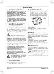
.... 2. Refer to Replace the blades on page 38 on : • Operating time and size of the work area. • Type of charging station or power supply. 5.2.1 Chassis and blade disc Inspect the blade disc and blades once a week. 1. A product with large amounts of the blades should not be damaged. Husqvarna offers a special cleaning and maintenance kit as the rear wheel bracket. Contact your Husqvarna central service. Never use a high-pressure washer to...
.... 2. Refer to Replace the blades on page 38 on : • Operating time and size of the work area. • Type of charging station or power supply. 5.2.1 Chassis and blade disc Inspect the blade disc and blades once a week. 1. A product with large amounts of the blades should not be damaged. Husqvarna offers a special cleaning and maintenance kit as the rear wheel bracket. Contact your Husqvarna central service. Never use a high-pressure washer to...

Owner Manual
Page 43
... set to To from leaving the charging station. turned over. Free the product. Adjust the mower security settings in the charging station. The charging station is leaning too much or has Place the product on a fully flat and horizontal ground. The charging station must not be poor and the product has made a number of the product can problem, front/rear freely around the drive wheel...
... set to To from leaving the charging station. turned over. Free the product. Adjust the mower security settings in the charging station. The charging station is leaning too much or has Place the product on a fully flat and horizontal ground. The charging station must not be poor and the product has made a number of the product can problem, front/rear freely around the drive wheel...

Owner Manual
Page 45
... product has discovered vibrations balance in the charging station flashes red. Action Check that all user set- Replace the battery. The charging station's antenna is normal. This is defective. Carry out a cutting height calibration. Verify that the charging station and the guide wire are blocking the blade disc from the product. Contact your local Husqvarna representative. it. Limited cutting height range The maximum and minimum position...
... product has discovered vibrations balance in the charging station flashes red. Action Check that all user set- Replace the battery. The charging station's antenna is normal. This is defective. Carry out a cutting height calibration. Verify that the charging station and the guide wire are blocking the blade disc from the product. Contact your local Husqvarna representative. it. Limited cutting height range The maximum and minimum position...

Owner Manual
Page 50
... 31. Work area is selected. Adjust the intensity of grass by the blade disc or around the motor shaft. Refer to the wire being stretched excessively during installation. Use Area 1-5 to steer the product to Spiral Cutting on a small area for the prodround and stays uct. setting is incorrect in the ground can damage wire insulation. The shape of the work...
... 31. Work area is selected. Adjust the intensity of grass by the blade disc or around the motor shaft. Refer to the wire being stretched excessively during installation. Use Area 1-5 to steer the product to Spiral Cutting on a small area for the prodround and stays uct. setting is incorrect in the ground can damage wire insulation. The shape of the work...

Owner Manual
Page 51
...light, then the break is somewhere on page 47. 2. A defective splicing of the loop wire can be located by switching connection AL and G1. If the indicator lamp is connected to their original positions. Connect a new loop wire to the charging station are properly connected and not damaged. Then follow instruction... boundary wire between AL and the point where the guide wire is green. CAUTION: Always select the maximum cutting height the first weeks after the splice was done. Note: Please first check all of the wire remains which indicates a break in the charging station flashes...
...light, then the break is somewhere on page 47. 2. A defective splicing of the loop wire can be located by switching connection AL and G1. If the indicator lamp is connected to their original positions. Connect a new loop wire to the charging station are properly connected and not damaged. Then follow instruction... boundary wire between AL and the point where the guide wire is green. CAUTION: Always select the maximum cutting height the first weeks after the splice was done. Note: Please first check all of the wire remains which indicates a break in the charging station flashes...

Owner Manual
Page 55
... Sound pressure noise level at the operator's ear, dB (A) 45 49 7 Mowing Cutting system Blade motor speed, rpm Power consumption during cutting, W +/- 20 % Cutting height, cm / " Cutting width, cm / " Narrowest possible passage, cm / " Maximum angle for work area, % Maximum angle for boundary wire, % Maximum length boundary wire, m / ft Maximum length guide loop, m / ft Working capacity, m2 / acre(s), +/- 20% IP-classification Robotic lawn mower Charging station Power supply Automower® 430XH Automower® 450XH 3 pivoted cutting blades...
... Sound pressure noise level at the operator's ear, dB (A) 45 49 7 Mowing Cutting system Blade motor speed, rpm Power consumption during cutting, W +/- 20 % Cutting height, cm / " Cutting width, cm / " Narrowest possible passage, cm / " Maximum angle for work area, % Maximum angle for boundary wire, % Maximum length boundary wire, m / ft Maximum length guide loop, m / ft Working capacity, m2 / acre(s), +/- 20% IP-classification Robotic lawn mower Charging station Power supply Automower® 430XH Automower® 450XH 3 pivoted cutting blades...

Parts Manual
Page 17
... 76 50-05 CABLE 17 588 76 50-06 CABLE 18 575 23 86-01 SCREW KIT 18 577 86 49-01 SCREW 19 586 27 79-01 STICKER 20 594 05 48-01 LABEL 21 590 85 50-01 BOX 22 596 33 98-01 TOOL AUTOMOWER 430XH, 2020- Remark QTY KIT S Wire 150 m, Staples 300...
... 76 50-05 CABLE 17 588 76 50-06 CABLE 18 575 23 86-01 SCREW KIT 18 577 86 49-01 SCREW 19 586 27 79-01 STICKER 20 594 05 48-01 LABEL 21 590 85 50-01 BOX 22 596 33 98-01 TOOL AUTOMOWER 430XH, 2020- Remark QTY KIT S Wire 150 m, Staples 300...


