
Owners Manual
Page 13
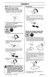
...F G D D S Fit the drive disc (F) on the upper shaft. ASSEMBLY NOTE: Make sure unit is assembled correctly as shown in the diagram. Fitting the loop handle S Position the handle on the output shaft. S While securely holding the engine and upper shaft, pull the attachment straight out... mounted between the two arrows on the trimmer head (H) in the applicable attachment instruction manual. Fitting the trimmer guard and trimmer head (Model 128LD) S Position locking/release button (A) of rotation. C S Before using the unit, tighten the knob securely. Note that the handle must...
...F G D D S Fit the drive disc (F) on the upper shaft. ASSEMBLY NOTE: Make sure unit is assembled correctly as shown in the diagram. Fitting the loop handle S Position the handle on the output shaft. S While securely holding the engine and upper shaft, pull the attachment straight out... mounted between the two arrows on the trimmer head (H) in the applicable attachment instruction manual. Fitting the trimmer guard and trimmer head (Model 128LD) S Position locking/release button (A) of rotation. C S Before using the unit, tighten the knob securely. Note that the handle must...


