Owner's Manual
Page 1
Installation Guide ENGLISH See page 2 Español Vea la página 21 90052/90053/90054/90058 Saturn™ Bath Ventilator with Light READ and SAVE THESE INSTRUCTIONS 028_41718_EngS_1.28.08_Arial.indd 1 1 41718-01 01/28/2008 1/28/08 10:47:06 AM
Installation Guide ENGLISH See page 2 Español Vea la página 21 90052/90053/90054/90058 Saturn™ Bath Ventilator with Light READ and SAVE THESE INSTRUCTIONS 028_41718_EngS_1.28.08_Arial.indd 1 1 41718-01 01/28/2008 1/28/08 10:47:06 AM
Owner's Manual
Page 2
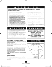
...AM CAUTION 1. TO CLEAN GRILLE: Use a mild detergent, such as listed below. Push up to the service panel. 3. American Society for installation in a wall. When cutting or drilling into the slot in a manner intended by the manufacturer. Never place a switch where it must not ... oiling. DO NOT use to prevent backdrafting. Use this product in ceilings up rear motor plate tab while pushing out on accidentally. Installation work and electrical wiring must be done by the National Fire Prevention Association (NFPA), and the 5. Do not use abrasive cloths,...
...AM CAUTION 1. TO CLEAN GRILLE: Use a mild detergent, such as listed below. Push up to the service panel. 3. American Society for installation in a wall. When cutting or drilling into the slot in a manner intended by the manufacturer. Never place a switch where it must not ... oiling. DO NOT use to prevent backdrafting. Use this product in ceilings up rear motor plate tab while pushing out on accidentally. Installation work and electrical wiring must be done by the National Fire Prevention Association (NFPA), and the 5. Do not use abrasive cloths,...
Owner's Manual
Page 3
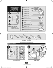
....indd 3 3 41718-01 01/28/2008 Loosen screws. 1/28/08 10:47:09 AM Not Included. If damaged, call 1-888-830-1326 for replacements. Before Installation 1 Tools Needed. (Not supplied) Estimated assembly time: 30 to 60 minutes NOTE: Remove all the parts. D 95044-01-000 E 95029-01-000 F 75191-01-000... G 03242-07-133 H 95491-01-000 x2 I Extra Screws * NOTE: Strain relief cable connector must be installed. x4 A *B *C 3/8" Cable Connector x2 I 74508-03-133 J 77521-01 K 65219 L 95583-01/02/03/04-000 M 75184-01-133 N 94990-01/02/03-000 ...
....indd 3 3 41718-01 01/28/2008 Loosen screws. 1/28/08 10:47:09 AM Not Included. If damaged, call 1-888-830-1326 for replacements. Before Installation 1 Tools Needed. (Not supplied) Estimated assembly time: 30 to 60 minutes NOTE: Remove all the parts. D 95044-01-000 E 95029-01-000 F 75191-01-000... G 03242-07-133 H 95491-01-000 x2 I Extra Screws * NOTE: Strain relief cable connector must be installed. x4 A *B *C 3/8" Cable Connector x2 I 74508-03-133 J 77521-01 K 65219 L 95583-01/02/03/04-000 M 75184-01-133 N 94990-01/02/03-000 ...
Owner's Manual
Page 5
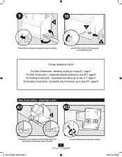
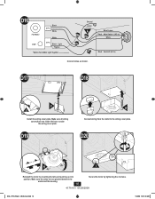
... access slug. Use second if needed. accessible from below go to step A11, page 5 For New Construction - attaching to step D11, page15 New Construction - Choose Installation Option For New Construction - accessible only from above go to joist A11 A12 E 5/8 5/8 1/2 1/2 Position the correct depth mark at the bottom edge of the joist...
... access slug. Use second if needed. accessible from below go to step A11, page 5 For New Construction - attaching to step D11, page15 New Construction - Choose Installation Option For New Construction - accessible only from above go to joist A11 A12 E 5/8 5/8 1/2 1/2 Position the correct depth mark at the bottom edge of the joist...
Owner's Manual
Page 6
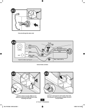
A13 Pull wires through the strain relief. A15 A016 E G Install the wiring cover plate. If ducting does not fit securely, an adapter may need to the outside. Connect 4" duct and vent to be purchased. 6 41718-...
A13 Pull wires through the strain relief. A15 A016 E G Install the wiring cover plate. If ducting does not fit securely, an adapter may need to the outside. Connect 4" duct and vent to be purchased. 6 41718-...
Owner's Manual
Page 9
... or under the wiring cover plate. B17 B18 Tighten screws. If ducting does not fit securely, an adapter may need to the outside. B20 B21 F G Install the wiring cover plate. Pull wires through the strain relief.
... or under the wiring cover plate. B17 B18 Tighten screws. If ducting does not fit securely, an adapter may need to the outside. B20 B21 F G Install the wiring cover plate. Pull wires through the strain relief.
Owner's Manual
Page 13
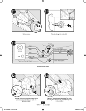
C23 C24 F H G Install the wiring cover plate. C22 Fan Motor Light Black 2 Pin White White 3 Pin Black Light *Option *Option Fan & Main Light Together Ground Green A Bare Copper Black Main Switch 1 (AC In) White Black Switch 2 (AC In) Connect wires as shown. C21 Tighten the strain relief screws. Make sure all wiring connections are inside the box or under the wiring cover plate. 13 41718-01 01/28/2008 Connect wiring from the motor to the wiring cover plate. 028_41718_EngS_1.28.08_Arial.indd 13 1/28/08 10:47:35 AM
C23 C24 F H G Install the wiring cover plate. C22 Fan Motor Light Black 2 Pin White White 3 Pin Black Light *Option *Option Fan & Main Light Together Ground Green A Bare Copper Black Main Switch 1 (AC In) White Black Switch 2 (AC In) Connect wires as shown. C21 Tighten the strain relief screws. Make sure all wiring connections are inside the box or under the wiring cover plate. 13 41718-01 01/28/2008 Connect wiring from the motor to the wiring cover plate. 028_41718_EngS_1.28.08_Arial.indd 13 1/28/08 10:47:35 AM
Owner's Manual
Page 16
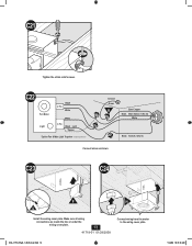
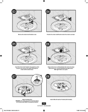
D17 D18 F G Install the wiring cover plate. D20 H I Reinstall the motor by tightening the 2 screws. 41718-01 01/28/2008 028_41718_EngS_1.28.08_Arial.indd 16 1/28/08 10:...
D17 D18 F G Install the wiring cover plate. D20 H I Reinstall the motor by tightening the 2 screws. 41718-01 01/28/2008 028_41718_EngS_1.28.08_Arial.indd 16 1/28/08 10:...
Owner's Manual
Page 18
.... E5 Position the strain relief bracket under the motor as shown. Slide light fixture over the lip of electrical shock, all 4 thumbscrews MUST be properly installed. 18 Install 2 Max 60 watt A-15 bulbs (Not Included). 41718-01 01/28/2008 028_41718_EngS_1.28.08_Arial.indd 18 1/28/08 10:47:48 AM E6...
.... E5 Position the strain relief bracket under the motor as shown. Slide light fixture over the lip of electrical shock, all 4 thumbscrews MUST be properly installed. 18 Install 2 Max 60 watt A-15 bulbs (Not Included). 41718-01 01/28/2008 028_41718_EngS_1.28.08_Arial.indd 18 1/28/08 10:47:48 AM E6...
Owner's Manual
Page 20
...labor costs for all insurance and freight or other document that establishes proof of purchase is not purchased and installed in your bath exhaust fan to the Hunter bath exhaust fan while in the U.S.A. THE DURATION OF ANY IMPLIED WARRANTY, INCLUDING, BUT NOT LIMITED TO,...warranty is voided if your Hunter bath exhaust fan freight prepaid. To obtain servicing, contact the nearest Hunter authorized service center of parts or accessories not authorized by us , mishandling, improper installation, modifications or damage to us , you will return your Hunter bath exhaust fan is required...
...labor costs for all insurance and freight or other document that establishes proof of purchase is not purchased and installed in your bath exhaust fan to the Hunter bath exhaust fan while in the U.S.A. THE DURATION OF ANY IMPLIED WARRANTY, INCLUDING, BUT NOT LIMITED TO,...warranty is voided if your Hunter bath exhaust fan freight prepaid. To obtain servicing, contact the nearest Hunter authorized service center of parts or accessories not authorized by us , mishandling, improper installation, modifications or damage to us , you will return your Hunter bath exhaust fan is required...


