Owner's Manual
Page 2
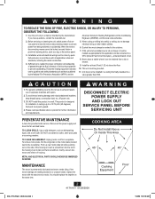
... DISCONNECT ELECTRIC POWER SUPPLY AND LOCK OUT SERVICE PANEL BEFORE SERVICING UNIT PREVENTATIVE MAINTENANCE A clean fan provides better service. MAINTENANCE The motor is designed for further information and requirements. Sufficient air is to tab) and twist screwdriver. Ducted fans must not be locked,... as appropriate for Heating, Refrigeration and Air-Conditioning Engineers (ASHRAE), and the local code authorities. 2. Gently vacuum fan, motor and interior of fuel burning equipment to exhaust hazardous or explosive materials and vapors. 2. METAL AND ELECTRICAL PARTS SHOULD NEVER ...
... DISCONNECT ELECTRIC POWER SUPPLY AND LOCK OUT SERVICE PANEL BEFORE SERVICING UNIT PREVENTATIVE MAINTENANCE A clean fan provides better service. MAINTENANCE The motor is designed for further information and requirements. Sufficient air is to tab) and twist screwdriver. Ducted fans must not be locked,... as appropriate for Heating, Refrigeration and Air-Conditioning Engineers (ASHRAE), and the local code authorities. 2. Gently vacuum fan, motor and interior of fuel burning equipment to exhaust hazardous or explosive materials and vapors. 2. METAL AND ELECTRICAL PARTS SHOULD NEVER ...
Owner's Manual
Page 4
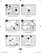
3 4 H E Remove the motor/blower from the housing. 5 Remove packing material. 6 Remove the pre-loaded screw tip covers. 7 G Back out the pre-loaded screw tips until flush with the side of the housing. 8 F Remove the wiring cover screw. 4 41718-01 01/28/2008 028_41718_EngS_1.28.08_Arial.indd 4 Remove the wiring cover. 1/28/08 10:47:11 AM
3 4 H E Remove the motor/blower from the housing. 5 Remove packing material. 6 Remove the pre-loaded screw tip covers. 7 G Back out the pre-loaded screw tips until flush with the side of the housing. 8 F Remove the wiring cover screw. 4 41718-01 01/28/2008 028_41718_EngS_1.28.08_Arial.indd 4 Remove the wiring cover. 1/28/08 10:47:11 AM
Owner's Manual
Page 6
A14 Fan Motor Light Black 2 Pin White White 3 Pin Black Light *Option *Option Fan & Main Light Together Ground Green A Bare Copper Black Main Switch 1 (AC In) White Black ...
A14 Fan Motor Light Black 2 Pin White White 3 Pin Black Light *Option *Option Fan & Main Light Together Ground Green A Bare Copper Black Main Switch 1 (AC In) White Black ...
Owner's Manual
Page 7
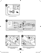
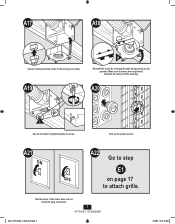
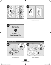
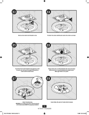
A19 H Reinstall the motor by tightening the 2 screws. A20 I Secure the motor by inserting the tabs and pushing up into position. A21 ON A22 Go to step E1 OFF on the power source. Test the motor. A17 0 A18 0 Connect wiring from the motor to attach grille. Make sure the wires are not pinched between the motor and the housing. Turn on page 17 to the wiring cover plate. If the motor does not run, check the plug connection. 7 41718-01 01/28/2008 028_41718_EngS_1.28.08_Arial.indd 7 1/28/08 10:47:18 AM
A19 H Reinstall the motor by tightening the 2 screws. A20 I Secure the motor by inserting the tabs and pushing up into position. A21 ON A22 Go to step E1 OFF on the power source. Test the motor. A17 0 A18 0 Connect wiring from the motor to attach grille. Make sure the wires are not pinched between the motor and the housing. Turn on page 17 to the wiring cover plate. If the motor does not run, check the plug connection. 7 41718-01 01/28/2008 028_41718_EngS_1.28.08_Arial.indd 7 1/28/08 10:47:18 AM
Owner's Manual
Page 9
... vent to be purchased. 9 41718-01 01/28/2008 028_41718_EngS_1.28.08_Arial.indd 9 1/28/08 10:47:24 AM B17 B18 Tighten screws. B19 Fan Motor Light Black 2 Pin White White 3 Pin Black Light *Option *Option Fan & Main Light Together Ground Green A Bare Copper Black Main Switch 1 (AC In) White Black...
... vent to be purchased. 9 41718-01 01/28/2008 028_41718_EngS_1.28.08_Arial.indd 9 1/28/08 10:47:24 AM B17 B18 Tighten screws. B19 Fan Motor Light Black 2 Pin White White 3 Pin Black Light *Option *Option Fan & Main Light Together Ground Green A Bare Copper Black Main Switch 1 (AC In) White Black...
Owner's Manual
Page 10
Reinstall the motor by tightening the 2 screws. B22 B23 H H Connect wiring from the motor to step E1 OFF on the power source. Turn on page 17 to attach grille. If the motor does not run, check the plug connection. 10 41718-01 01/28/2008 028_41718_EngS_1.28.08_Arial.indd 10 1/28/08 10:47:27 AM B26 ON B27 Go to the wiring cover plate. Test the motor. B24 B25 I Secure the motor by inserting the tabs and pushing up into position. Make sure the wires are not pinched between the motor and the housing.
Reinstall the motor by tightening the 2 screws. B22 B23 H H Connect wiring from the motor to step E1 OFF on the power source. Turn on page 17 to attach grille. If the motor does not run, check the plug connection. 10 41718-01 01/28/2008 028_41718_EngS_1.28.08_Arial.indd 10 1/28/08 10:47:27 AM B26 ON B27 Go to the wiring cover plate. Test the motor. B24 B25 I Secure the motor by inserting the tabs and pushing up into position. Make sure the wires are not pinched between the motor and the housing.
Owner's Manual
Page 11
... depth mark at the bottom edge of the joist based on the thickness of screws by using holes as a template to accommodate the new motor housing (8"x 8.5"). 8" 8.5" Use the motor housing as a template. 11 41718-01 01/28/2008 028_41718_EngS_1.28.08_Arial.indd 11 1/28/08 10:47:30 AM C13 Slide the...
... depth mark at the bottom edge of the joist based on the thickness of screws by using holes as a template to accommodate the new motor housing (8"x 8.5"). 8" 8.5" Use the motor housing as a template. 11 41718-01 01/28/2008 028_41718_EngS_1.28.08_Arial.indd 11 1/28/08 10:47:30 AM C13 Slide the...
Owner's Manual
Page 13
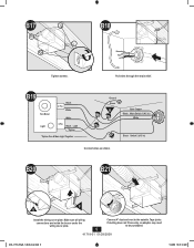
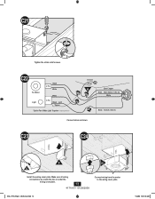
Make sure all wiring connections are inside the box or under the wiring cover plate. 13 41718-01 01/28/2008 Connect wiring from the motor to the wiring cover plate. 028_41718_EngS_1.28.08_Arial.indd 13 1/28/08 10:47:35 AM C22 Fan Motor Light Black 2 Pin White White 3 Pin Black Light *Option *Option Fan & Main Light Together Ground Green A Bare Copper Black Main Switch 1 (AC In) White Black Switch 2 (AC In) Connect wires as shown. C23 C24 F H G Install the wiring cover plate. C21 Tighten the strain relief screws.
Make sure all wiring connections are inside the box or under the wiring cover plate. 13 41718-01 01/28/2008 Connect wiring from the motor to the wiring cover plate. 028_41718_EngS_1.28.08_Arial.indd 13 1/28/08 10:47:35 AM C22 Fan Motor Light Black 2 Pin White White 3 Pin Black Light *Option *Option Fan & Main Light Together Ground Green A Bare Copper Black Main Switch 1 (AC In) White Black Switch 2 (AC In) Connect wires as shown. C23 C24 F H G Install the wiring cover plate. C21 Tighten the strain relief screws.
Owner's Manual
Page 14
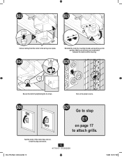
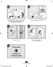
Make sure the wires are not pinched between the motor and the housing. Test the motor. C27 C28 ON OFF Turn on page 17 to attach grille. I Secure the motor by inserting the tabs and pushing up into position. If the motor does not run, check the plug connection. 028_41718_EngS_1.28.08_Arial.indd 14 14 41718-01 01/28/2008 1/28/08 10:47:38 AM C29 Go to step E1 on the power source. C25 C26 H Reinstall the motor by tightening the 2 screws.
Make sure the wires are not pinched between the motor and the housing. Test the motor. C27 C28 ON OFF Turn on page 17 to attach grille. I Secure the motor by inserting the tabs and pushing up into position. If the motor does not run, check the plug connection. 028_41718_EngS_1.28.08_Arial.indd 14 14 41718-01 01/28/2008 1/28/08 10:47:38 AM C29 Go to step E1 on the power source. C25 C26 H Reinstall the motor by tightening the 2 screws.
Owner's Manual
Page 15
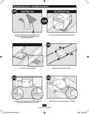
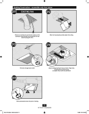
D13 Move the housing into joist or framing. 15 41718-01 01/28/2008 028_41718_EngS_1.28.08_Arial.indd 15 1/28/08 10:47:40 AM accessible only from below D11 EXISTING FAN D12 E Remove an existing fan and check to make sure the opening is large enough to duct connector. D15 Attach existing ducting to accommodate the new motor housing (8"x 8.5"). Tape joints. Existing Construction - D14 2 1 Pull wires through strain relief. If ducting does not fit securely, an adapter may need to be purchased. E Screw pre-loaded screws into position above the ceiling.
D13 Move the housing into joist or framing. 15 41718-01 01/28/2008 028_41718_EngS_1.28.08_Arial.indd 15 1/28/08 10:47:40 AM accessible only from below D11 EXISTING FAN D12 E Remove an existing fan and check to make sure the opening is large enough to duct connector. D15 Attach existing ducting to accommodate the new motor housing (8"x 8.5"). Tape joints. Existing Construction - D14 2 1 Pull wires through strain relief. If ducting does not fit securely, an adapter may need to be purchased. E Screw pre-loaded screws into position above the ceiling.
Owner's Manual
Page 16
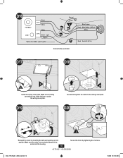
.../28/2008 028_41718_EngS_1.28.08_Arial.indd 16 1/28/08 10:47:43 AM Make sure all wiring connections are not pinched between the motor and the housing. 16 Secure the motor by inserting the tabs and pushing up into position. D17 D18 F G Install the wiring cover plate. D19 H Connect wiring from the... the wiring cover plate. Make sure the wires are inside the box or under the wiring cover plate. D16 Fan Motor Light 2 Pin Black White White 3 Pin Black Light *Option *Option Fan & Main Light Together Ground Green A Bare Copper Black Main Switch 1 (AC In) White Black ...
.../28/2008 028_41718_EngS_1.28.08_Arial.indd 16 1/28/08 10:47:43 AM Make sure all wiring connections are not pinched between the motor and the housing. 16 Secure the motor by inserting the tabs and pushing up into position. D17 D18 F G Install the wiring cover plate. D19 H Connect wiring from the... the wiring cover plate. Make sure the wires are inside the box or under the wiring cover plate. D16 Fan Motor Light 2 Pin Black White White 3 Pin Black Light *Option *Option Fan & Main Light Together Ground Green A Bare Copper Black Main Switch 1 (AC In) White Black ...
Owner's Manual
Page 17
D21 Turn on page 17 to step E1 on the power source. D22 ON OFF Test the motor. Attaching the Grille E1 E2 E M L Remove the thumbscrews. 028_41718_EngS_1.28.08_Arial.indd 17 17 41718-01 01/28/2008 Connect wiring harness. 1/28/08 10:47:45 AM If the motor does not run, check the plug connection. D23 Go to attach grille.
D21 Turn on page 17 to step E1 on the power source. D22 ON OFF Test the motor. Attaching the Grille E1 E2 E M L Remove the thumbscrews. 028_41718_EngS_1.28.08_Arial.indd 17 17 41718-01 01/28/2008 Connect wiring harness. 1/28/08 10:47:45 AM If the motor does not run, check the plug connection. D23 Go to attach grille.
Owner's Manual
Page 18
... bulbs (Not Included). 41718-01 01/28/2008 028_41718_EngS_1.28.08_Arial.indd 18 1/28/08 10:47:48 AM E7 Align posts A, B, C and D (stamped into motor housing) with posts A, B, C and D (stamped into light fixture). E6 L Insert the strain relief bracket's dog-leg tab so that it hooks over posts. E8 M ...Attach thumbscrews. E5 Position the strain relief bracket under the motor as shown. WARNING: To reduce the risk of the motor. E3 E4 J K Remove the strain relief bracket screw.
... bulbs (Not Included). 41718-01 01/28/2008 028_41718_EngS_1.28.08_Arial.indd 18 1/28/08 10:47:48 AM E7 Align posts A, B, C and D (stamped into motor housing) with posts A, B, C and D (stamped into light fixture). E6 L Insert the strain relief bracket's dog-leg tab so that it hooks over posts. E8 M ...Attach thumbscrews. E5 Position the strain relief bracket under the motor as shown. WARNING: To reduce the risk of the motor. E3 E4 J K Remove the strain relief bracket screw.
Owner's Manual
Page 20
...free of charge. If no replacement part can be provided, we will, at our option, either refund the actual purchase price of your Hunter bath exhaust fan motor fails at any time within one -year period, you will be responsible for all parts and labor costs for repairs on all parts ..., you will be responsible for all parts and labor costs for repairs on the bath exhaust fan except for motor repairs as provided below. To obtain servicing, contact the nearest Hunter authorized service center of purchase is required when requesting warranty service. If we will not be responsible for all ...
...free of charge. If no replacement part can be provided, we will, at our option, either refund the actual purchase price of your Hunter bath exhaust fan motor fails at any time within one -year period, you will be responsible for all parts and labor costs for repairs on all parts ..., you will be responsible for all parts and labor costs for repairs on the bath exhaust fan except for motor repairs as provided below. To obtain servicing, contact the nearest Hunter authorized service center of purchase is required when requesting warranty service. If we will not be responsible for all ...


