Owner's Manual
Page 5
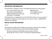
... screws and two wall anchors for assistance. IMPORTANT INFORMATION This thermostat is designed to work on the following heating and cooling systems: Up to 2 Stage Heat/2 Stage Cool Heat Only or Cool Only Systems Single and Multi-Stage Heat Pumps Gas, Electric or Oil Systems Millivolt Systems 2-wire Hydronic Systems AC or Hard-wired This thermostat is not...
... screws and two wall anchors for assistance. IMPORTANT INFORMATION This thermostat is designed to work on the following heating and cooling systems: Up to 2 Stage Heat/2 Stage Cool Heat Only or Cool Only Systems Single and Multi-Stage Heat Pumps Gas, Electric or Oil Systems Millivolt Systems 2-wire Hydronic Systems AC or Hard-wired This thermostat is not...
Owner's Manual
Page 12
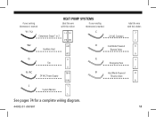
if your existing thermostat is marked: HEAT PUMP SYSTEMS label the wire with this sticker: if your existing thermostat is marked: label the wire with this sticker: Y1 / Y2 Compressor Stage 1 or 2 Y1 Y2 Y2 Y1 C 24 VAC Common C C O W2 Auxilliary Heat W2 W2 O Cool Mode Powered Reverse Valve O G Fan G G E Emergency Heat E E R/RC R / RC 24 VAC Power Supply R/RC B B Heat Mode Powered Reverse Valve B L L System Monitor L See pages 74 for a complete wiring diagram. 44002-01 r051807 11
if your existing thermostat is marked: HEAT PUMP SYSTEMS label the wire with this sticker: if your existing thermostat is marked: label the wire with this sticker: Y1 / Y2 Compressor Stage 1 or 2 Y1 Y2 Y2 Y1 C 24 VAC Common C C O W2 Auxilliary Heat W2 W2 O Cool Mode Powered Reverse Valve O G Fan G G E Emergency Heat E E R/RC R / RC 24 VAC Power Supply R/RC B B Heat Mode Powered Reverse Valve B L L System Monitor L See pages 74 for a complete wiring diagram. 44002-01 r051807 11
Owner's Manual
Page 28
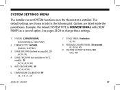
SYSTEM SETTINGS MENU The installer can set SYSTEM functions once the thermostat is CONVENTIONAL with (HEAT PUMP) as a second option. See pages 28-29 to change these settings. 1. FURNACE TYPE: GAS/OIL (GAS/OIL, ELECTRIC) 3. STAGE ... 44002-01 r051807 7. Example: the default SYSTEM TYPE is installed. STAGE TIMER: 0 minutes (0, 30) 8. SYSTEM: CONVENTIONAL (CONVENTIONAL, HEAT PUMP) 2. STAGE ONE SPAN (defined on 1H/1C models): 2F (2F, 3F, 4F, 5F, 6F) 5. RESIDUAL COOLING TIMER: 30 seconds (0, 30, 60, 90) 9. AUTO SEASON SPAN: 5F (3F, 4F, 5F, 6F) 6. The default settings...
SYSTEM SETTINGS MENU The installer can set SYSTEM functions once the thermostat is CONVENTIONAL with (HEAT PUMP) as a second option. See pages 28-29 to change these settings. 1. FURNACE TYPE: GAS/OIL (GAS/OIL, ELECTRIC) 3. STAGE ... 44002-01 r051807 7. Example: the default SYSTEM TYPE is installed. STAGE TIMER: 0 minutes (0, 30) 8. SYSTEM: CONVENTIONAL (CONVENTIONAL, HEAT PUMP) 2. STAGE ONE SPAN (defined on 1H/1C models): 2F (2F, 3F, 4F, 5F, 6F) 5. RESIDUAL COOLING TIMER: 30 seconds (0, 30, 60, 90) 9. AUTO SEASON SPAN: 5F (3F, 4F, 5F, 6F) 6. The default settings...
Owner's Manual
Page 38
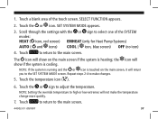
Touch a blank area of the SYSTEM modes: HEAT ( icon, red screen) EMHEAT (only for Heat Pump Systems) AUTO ( and icons) COOL ( icon, blue screen) OFF (no icon) 4. SET SYSTEM MODE appears. 3. Touch ...system is running and the or icon is touched on the main screen if the system is cooling. The icon will return you to high or low extremes will show on the main screen, it will... show if the system is heating; the icon will not make changes. 5. Touch to return to adjust the temperature. Repeat steps 2-4 ...
Touch a blank area of the SYSTEM modes: HEAT ( icon, red screen) EMHEAT (only for Heat Pump Systems) AUTO ( and icons) COOL ( icon, blue screen) OFF (no icon) 4. SET SYSTEM MODE appears. 3. Touch ...system is running and the or icon is touched on the main screen if the system is cooling. The icon will return you to high or low extremes will show on the main screen, it will... show if the system is heating; the icon will not make changes. 5. Touch to return to adjust the temperature. Repeat steps 2-4 ...

Owner's Manual
Page 75
RC/R C Y1 Heat Pump Systems Optional Jumper Y2 W2 E O B G L 24VAC Supply Compressor Compressor Auxiliary Emergency Reversing Valve Reversing Valve Fan System Stage 1 Stage 2 Heat Heat Cool Heat Control Monitor 24VAC Common (if available) Number of wires connected depends on systems without an E wire. 74 44002-01 r051807 Not all terminals need to be connected. • Add jumper between W2 and E terminals on the heat pump system requirement.
RC/R C Y1 Heat Pump Systems Optional Jumper Y2 W2 E O B G L 24VAC Supply Compressor Compressor Auxiliary Emergency Reversing Valve Reversing Valve Fan System Stage 1 Stage 2 Heat Heat Cool Heat Control Monitor 24VAC Common (if available) Number of wires connected depends on systems without an E wire. 74 44002-01 r051807 Not all terminals need to be connected. • Add jumper between W2 and E terminals on the heat pump system requirement.


