
Owner's Manual
Page 2
Table Of Contents At A Glance Know Your Thermostat 4 Installation Remove Old Thermostat 8 Wiring Documentation 10 Wiring Labeling 12 Mount Wallplate and Thermostat 14 Wiring Diagrams 20 Selector Switches 22 Operation Selector Switches 24 Set Temperature 25 Filter Monitor 26 Span Setting 27 Low Battery Warning 28 Error Mode 29 Features Additional Features 30 Troubleshooting 31 Thermostat Assistance Technical Support 33 Warranty 1 year Guarantee 34
Table Of Contents At A Glance Know Your Thermostat 4 Installation Remove Old Thermostat 8 Wiring Documentation 10 Wiring Labeling 12 Mount Wallplate and Thermostat 14 Wiring Diagrams 20 Selector Switches 22 Operation Selector Switches 24 Set Temperature 25 Filter Monitor 26 Span Setting 27 Low Battery Warning 28 Error Mode 29 Features Additional Features 30 Troubleshooting 31 Thermostat Assistance Technical Support 33 Warranty 1 year Guarantee 34
Owner's Manual
Page 3
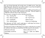
Using this manual for buying a Hunter product! Please read this digital thermostat will NOT control single-stage or multi-stage heat pumps or 110/220 V baseboard electric heating systems. This thermostat includes two #8 slotted screws and two wall anchors for mounting. Standing... Electronic Ignition * Oil - This thermostat is designed to 5pm Central Time. Fired Furnace * Gas - To install your thermostat. Your new Hunter thermostat will provide years of reliable service. Thank you require further assistance, call Hunter Technical Support at 1-888-830-1326...
Using this manual for buying a Hunter product! Please read this digital thermostat will NOT control single-stage or multi-stage heat pumps or 110/220 V baseboard electric heating systems. This thermostat includes two #8 slotted screws and two wall anchors for mounting. Standing... Electronic Ignition * Oil - This thermostat is designed to 5pm Central Time. Fired Furnace * Gas - To install your thermostat. Your new Hunter thermostat will provide years of reliable service. Thank you require further assistance, call Hunter Technical Support at 1-888-830-1326...
Owner's Manual
Page 4
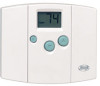
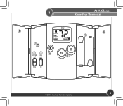
At A Glance Know Your Thermostat 1 1. Filter Key: Resets the filter change counter to power-up settings. 2. Fan Switch: Fan switch for adjusting the Span. 6. Also used for Heat, Cool, and ... AA 1.5V batteries. 8. Front Doors: Covers keys and batteries when not used for Automatic or Continuous fan operation.. 4. Open with a paper clip to reset the thermostat and return to zero. 5. Reset: Press with one finger from top or bottom. 4 44043-01 • 02/19/2010 Up and Down Keys: Keys for...
At A Glance Know Your Thermostat 1 1. Filter Key: Resets the filter change counter to power-up settings. 2. Fan Switch: Fan switch for adjusting the Span. 6. Also used for Heat, Cool, and ... AA 1.5V batteries. 8. Front Doors: Covers keys and batteries when not used for Automatic or Continuous fan operation.. 4. Open with a paper clip to reset the thermostat and return to zero. 5. Reset: Press with one finger from top or bottom. 4 44043-01 • 02/19/2010 Up and Down Keys: Keys for...
Owner's Manual
Page 5
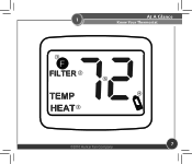
1 At A Glance Know Your Thermostat 8 1 6 8 7 23 4 5 ©2010 Hunter Fan Company 5
1 At A Glance Know Your Thermostat 8 1 6 8 7 23 4 5 ©2010 Hunter Fan Company 5
Owner's Manual
Page 6
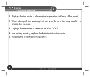
Low battery warning, replace the batteries in Celsius of Farenheit. 2. Displays the thermostat is showing the temperature in the thermostat. 5. At A Glance Know Your Thermostat 1 1. Indicates the current room temperature. 6 44043-01 • 02/19/2010 When displayed, this warning indicates your furnace filter may need to run HEAT or COOL. 4. Displays the thermostat is set to be checked or replaced. 3.
Low battery warning, replace the batteries in Celsius of Farenheit. 2. Displays the thermostat is showing the temperature in the thermostat. 5. At A Glance Know Your Thermostat 1 1. Indicates the current room temperature. 6 44043-01 • 02/19/2010 When displayed, this warning indicates your furnace filter may need to run HEAT or COOL. 4. Displays the thermostat is set to be checked or replaced. 3.
Owner's Manual
Page 7
1 At A Glance Know Your Thermostat 1 2 5 4 3 ©2010 Hunter Fan Company 7
1 At A Glance Know Your Thermostat 1 2 5 4 3 ©2010 Hunter Fan Company 7
Owner's Manual
Page 8
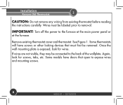
... have doors that must be connected to expose wires and mounting screws. 8 44043-01 • 02/19/2010 Remove existing thermostat cover and thermostat. If wires are not visible, they may be labeled prior to the furnace at the main power panel or at the furnace. Some models have ... to the back of the wallplate. Turn off the power to removal. Once the wall mounting plate is exposed, look for wires. Installation Remove Old Thermostat 2 CAUTION: Do not remove any wiring from existing...
... have doors that must be connected to expose wires and mounting screws. 8 44043-01 • 02/19/2010 Remove existing thermostat cover and thermostat. If wires are not visible, they may be labeled prior to the furnace at the main power panel or at the furnace. Some models have ... to the back of the wallplate. Turn off the power to removal. Once the wall mounting plate is exposed, look for wires. Installation Remove Old Thermostat 2 CAUTION: Do not remove any wiring from existing...
Owner's Manual
Page 9
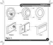
2 Installation Remove Old Thermostat RC Y G W Wallplate Thermostat Cover RC Y G W Wallplate Figure 1. Thermostat ©2010 Hunter Fan Company Cover 9
2 Installation Remove Old Thermostat RC Y G W Wallplate Thermostat Cover RC Y G W Wallplate Figure 1. Thermostat ©2010 Hunter Fan Company Cover 9
Owner's Manual
Page 10
Wire color does not indicate the function of your system type and proper wiring, should you need to refer to contact them. This will allow you to keep a record of the wire, this is being used only to write down your wire colors and the letter designations on the old thermostat. This will also help determine which wire has what letter designation. 10 44043-01 • 02/19/2010 to help our Technical Support Department determine your old thermostat's wiring configuration should you need to it at a later time. Installation Wiring Documentation 2 Use table A.
Wire color does not indicate the function of your system type and proper wiring, should you need to refer to contact them. This will allow you to keep a record of the wire, this is being used only to write down your wire colors and the letter designations on the old thermostat. This will also help determine which wire has what letter designation. 10 44043-01 • 02/19/2010 to help our Technical Support Department determine your old thermostat's wiring configuration should you need to it at a later time. Installation Wiring Documentation 2 Use table A.
Owner's Manual
Page 12
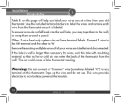
..., or wrap them around a pencil. on this page will help you may tape them to label the wires and remove each wire from the thermostat once it is larger than necessary for wires, seal this hole with insulating material so that no hot or cold air can enter the back... do not fall back into the wall hole, you label your wires are labelled and disconnected. Remove the existing wallplate once all of the thermostat from your old thermostat. Installation Wiring Labeling 2 Table B. To ensure wires do not use. Often, 2-wire heat only systems do not have terminal labels. This wire ...
..., or wrap them around a pencil. on this page will help you may tape them to label the wires and remove each wire from the thermostat once it is larger than necessary for wires, seal this hole with insulating material so that no hot or cold air can enter the back... do not fall back into the wall hole, you label your wires are labelled and disconnected. Remove the existing wallplate once all of the thermostat from your old thermostat. Installation Wiring Labeling 2 Table B. To ensure wires do not use. Often, 2-wire heat only systems do not have terminal labels. This wire ...
Owner's Manual
Page 13
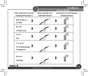
2 If the code letter on your then mark the wire existing thermostat is with label shown RH, R, VR or 4 24 Volt RC, VC 24 Volt Cool G or F Fan Installation Wiring Labeling and connect to thermostat terminal shown x x x Y, C or M x Air Conditioning Compressor W or H Heating Table B. ©2010 Hunter Fan Company x 13
2 If the code letter on your then mark the wire existing thermostat is with label shown RH, R, VR or 4 24 Volt RC, VC 24 Volt Cool G or F Fan Installation Wiring Labeling and connect to thermostat terminal shown x x x Y, C or M x Air Conditioning Compressor W or H Heating Table B. ©2010 Hunter Fan Company x 13
Owner's Manual
Page 14
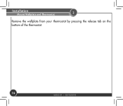
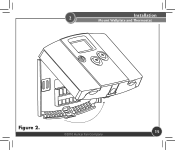
Installation Mount Wallplate and Thermostat 2 Remove the wallplate from your thermostat by pressing the release tab on the bottom of the thermostat. 14 44043-01 • 02/19/2010
Installation Mount Wallplate and Thermostat 2 Remove the wallplate from your thermostat by pressing the release tab on the bottom of the thermostat. 14 44043-01 • 02/19/2010
Owner's Manual
Page 15
2 Installation Mount Wallplate and Thermostat Figure 2. ©2010 Hunter Fan Company 15
2 Installation Mount Wallplate and Thermostat Figure 2. ©2010 Hunter Fan Company 15
Owner's Manual
Page 16
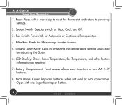
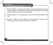
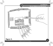
Insert mounting screws provided into the holes until flush with those on wall and pull existing wires through large opening . Installation Mount Wallplate and Thermostat 2 1. Reposition wallplate to wall, pulling wires through large opening . Then level for plastic anchors provided, if your existing holes do not line up with wall. 3. Mark holes for appearance. Drill holes with 3/16" bit and gently tap anchors into wall anchor and tighten. 16 44043-01 • 02/19/2010 Position wallplate on the wallplate. 2.
Insert mounting screws provided into the holes until flush with those on wall and pull existing wires through large opening . Installation Mount Wallplate and Thermostat 2 1. Reposition wallplate to wall, pulling wires through large opening . Then level for plastic anchors provided, if your existing holes do not line up with wall. 3. Mark holes for appearance. Drill holes with 3/16" bit and gently tap anchors into wall anchor and tighten. 16 44043-01 • 02/19/2010 Position wallplate on the wallplate. 2.
Owner's Manual
Page 17
2 Installation Mount Wallplate and Thermostat Figure 3. ©2010 Hunter Fan Company 17
2 Installation Mount Wallplate and Thermostat Figure 3. ©2010 Hunter Fan Company 17
Owner's Manual
Page 18
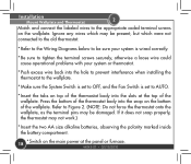
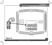
... to tighten the terminal screws securely, otherwise a loose wire could cause operational problems with your system or thermostat. * Push excess wire back into the hole to prevent interference when installing the thermostat to the wallplate. * Make sure the System Switch is set to OFF, and the Fan Switch is... set to Figure 2. (NOTE: Do not force the thermostat onto the wallplate, as the terminal pins may not work.) * Insert the two AA size alkaline batteries, observing the polarity marked inside the battery ...
... to tighten the terminal screws securely, otherwise a loose wire could cause operational problems with your system or thermostat. * Push excess wire back into the hole to prevent interference when installing the thermostat to the wallplate. * Make sure the System Switch is set to OFF, and the Fan Switch is... set to Figure 2. (NOTE: Do not force the thermostat onto the wallplate, as the terminal pins may not work.) * Insert the two AA size alkaline batteries, observing the polarity marked inside the battery ...
Owner's Manual
Page 19
2 Installation Mount Wallplate and Thermostat Figure 4. ©2010 Hunter Fan Company 19
2 Installation Mount Wallplate and Thermostat Figure 4. ©2010 Hunter Fan Company 19
Owner's Manual
Page 22
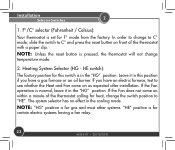
...mode from the factory. In order to change to C° mode, slide the switch to C° and press the reset button on front of the thermostat calling for this position if you have a gas furnace or an oil burner. HE switch): The factory position for heat, change temperature mode. 2. If ...the Fan does not come on within a minute of the thermostat with a paper clip. NOTE: "HG" position is for gas and most other systems. "HE" position is pressed, the thermostat will not change the switch position to see whether the Heat and Fan come on as...
...mode from the factory. In order to change to C° mode, slide the switch to C° and press the reset button on front of the thermostat calling for this position if you have a gas furnace or an oil burner. HE switch): The factory position for heat, change temperature mode. 2. If ...the Fan does not come on within a minute of the thermostat with a paper clip. NOTE: "HG" position is for gas and most other systems. "HE" position is pressed, the thermostat will not change the switch position to see whether the Heat and Fan come on as...
Owner's Manual
Page 24
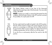
... the Fan on continuously, slide the Fan switch to prevent the possibility of a rapid system On-Off. NOTE: Anytime you install or remove the thermostat from the wallplate, slide the System Selector to the OFF position to the ON position. 24 44043-01 • 02/19/2010 Operation Selector Switches... 3 The System Selector switch on the front of the thermostat determines the operating mode of your furnace after its warm-up delay. In a normal gas or oil furnace, the Fan will turn on with normal...
... the Fan on continuously, slide the Fan switch to prevent the possibility of a rapid system On-Off. NOTE: Anytime you install or remove the thermostat from the wallplate, slide the System Selector to the OFF position to the ON position. 24 44043-01 • 02/19/2010 Operation Selector Switches... 3 The System Selector switch on the front of the thermostat determines the operating mode of your furnace after its warm-up delay. In a normal gas or oil furnace, the Fan will turn on with normal...
Owner's Manual
Page 26
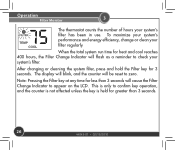
..., and the counter is not affected unless the key is only to zero. When the total system run time for 3 seconds. Operation Filter Monitor 3 The thermostat counts the number of hours your system's filter has been in use.
..., and the counter is not affected unless the key is only to zero. When the total system run time for 3 seconds. Operation Filter Monitor 3 The thermostat counts the number of hours your system's filter has been in use.

