
Owner's Manual
Page 2
Table Of Contents At A Glance Know Your Thermostat 4 Installation Remove Old Thermostat 8 Wiring Documentation 10 Wiring Labeling 12 Mount Wallplate and Thermostat 14 Wiring Diagrams 20 Selector Switches 22 Operation Selector Switches 24 Set Temperature 25 Filter Monitor 26 Span Setting 27 Low Battery Warning 28 Error Mode 29 Features Additional Features 30 Troubleshooting 31 Thermostat Assistance Technical Support 33 Warranty 1 year Guarantee 34
Table Of Contents At A Glance Know Your Thermostat 4 Installation Remove Old Thermostat 8 Wiring Documentation 10 Wiring Labeling 12 Mount Wallplate and Thermostat 14 Wiring Diagrams 20 Selector Switches 22 Operation Selector Switches 24 Set Temperature 25 Filter Monitor 26 Span Setting 27 Low Battery Warning 28 Error Mode 29 Features Additional Features 30 Troubleshooting 31 Thermostat Assistance Technical Support 33 Warranty 1 year Guarantee 34
Owner's Manual
Page 3
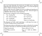
... Systems * Electric Air Conditioning This thermostat will provide years of reliable service. Standing Pilot * Oil - If you for buying a Hunter product! This thermostat is designed to 5pm Central Time. Fired Furnace * Gas - Fired Boilers * Electric Furnace * Gas - Your new Hunter thermostat will NOT control single-stage or multi-stage heat pumps or 110/220 V baseboard electric heating systems. This thermostat includes two #8 slotted screws and two wall anchors for mounting. Using this manual for complete instructions on...
... Systems * Electric Air Conditioning This thermostat will provide years of reliable service. Standing Pilot * Oil - If you for buying a Hunter product! This thermostat is designed to 5pm Central Time. Fired Furnace * Gas - Fired Boilers * Electric Furnace * Gas - Your new Hunter thermostat will NOT control single-stage or multi-stage heat pumps or 110/220 V baseboard electric heating systems. This thermostat includes two #8 slotted screws and two wall anchors for mounting. Using this manual for complete instructions on...
Owner's Manual
Page 4
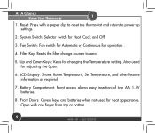
...: Resets the filter change counter to power-up settings. 2. Open with a paper clip to reset the thermostat and return to zero. 5. Also used for adjusting the Span. 6. LCD Display: Shows Room Temperature, Set Temperature, and other feature information as required. 7. System Switch: Selector switch for Automatic or Continuous fan operation.. 4. Reset: Press with one finger from top or bottom. 4 44043-01 • 02/19/2010 At A Glance Know Your Thermostat 1 1. Fan Switch: Fan switch for Heat, Cool...
...: Resets the filter change counter to power-up settings. 2. Open with a paper clip to reset the thermostat and return to zero. 5. Also used for adjusting the Span. 6. LCD Display: Shows Room Temperature, Set Temperature, and other feature information as required. 7. System Switch: Selector switch for Automatic or Continuous fan operation.. 4. Reset: Press with one finger from top or bottom. 4 44043-01 • 02/19/2010 At A Glance Know Your Thermostat 1 1. Fan Switch: Fan switch for Heat, Cool...
Owner's Manual
Page 6
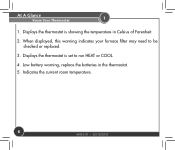
At A Glance Know Your Thermostat 1 1. Low battery warning, replace the batteries in Celsius of Farenheit. 2. Indicates the current room temperature. 6 44043-01 • 02/19/2010 Displays the thermostat is showing the temperature in the thermostat. 5. When displayed, this warning indicates your furnace filter may need to run HEAT or COOL. 4. Displays the thermostat is set to be checked or replaced. 3.
At A Glance Know Your Thermostat 1 1. Low battery warning, replace the batteries in Celsius of Farenheit. 2. Indicates the current room temperature. 6 44043-01 • 02/19/2010 Displays the thermostat is showing the temperature in the thermostat. 5. When displayed, this warning indicates your furnace filter may need to run HEAT or COOL. 4. Displays the thermostat is set to be checked or replaced. 3.
Owner's Manual
Page 8
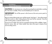
... 1. Installation Remove Old Thermostat 2 CAUTION: Do not remove any wiring from existing thermostat before reading the instructions carefully. Turn off the power to removal. Again, look for screws, tabs, etc. Remove existing thermostat cover and thermostat. Once the wall mounting plate is exposed, look for wires. If wires are not visible, they may be labeled prior to the furnace at the main power panel or at the furnace. IMPORTANT! Wires must first be removed.
... 1. Installation Remove Old Thermostat 2 CAUTION: Do not remove any wiring from existing thermostat before reading the instructions carefully. Turn off the power to removal. Again, look for screws, tabs, etc. Remove existing thermostat cover and thermostat. Once the wall mounting plate is exposed, look for wires. If wires are not visible, they may be labeled prior to the furnace at the main power panel or at the furnace. IMPORTANT! Wires must first be removed.
Owner's Manual
Page 10
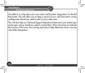
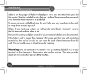
Installation Wiring Documentation 2 Use table A. Wire color does not indicate the function of your old thermostat's wiring configuration should you need to help our Technical Support Department determine your system type and proper wiring, should you to keep a record of the wire, this is being used only to contact them. This will allow you need to refer to write down your wire colors and the letter designations on the old thermostat. This will also help determine which wire has what letter designation. 10 44043-01 • 02/19/2010 to it at a later time.
Installation Wiring Documentation 2 Use table A. Wire color does not indicate the function of your old thermostat's wiring configuration should you need to help our Technical Support Department determine your system type and proper wiring, should you to keep a record of the wire, this is being used only to contact them. This will allow you need to refer to write down your wire colors and the letter designations on the old thermostat. This will also help determine which wire has what letter designation. 10 44043-01 • 02/19/2010 to it at a later time.
Owner's Manual
Page 12
... wall. Connect 1 wire to the RH terminal and the other to non-battery powered thermostats. 12 44043-01 • 02/19/2010 If the hole in wall is labeled. Tape up the wire and do not fall back into the wall hole, you label your wires one at a time from your wires are labelled and disconnected. To ensure wires do not use. This wire provides electricity to W. Installation Wiring...
... wall. Connect 1 wire to the RH terminal and the other to non-battery powered thermostats. 12 44043-01 • 02/19/2010 If the hole in wall is labeled. Tape up the wire and do not fall back into the wall hole, you label your wires one at a time from your wires are labelled and disconnected. To ensure wires do not use. This wire provides electricity to W. Installation Wiring...
Owner's Manual
Page 13
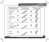
2 If the code letter on your then mark the wire existing thermostat is with label shown RH, R, VR or 4 24 Volt RC, VC 24 Volt Cool G or F Fan Installation Wiring Labeling and connect to thermostat terminal shown x x x Y, C or M x Air Conditioning Compressor W or H Heating Table B. ©2010 Hunter Fan Company x 13
2 If the code letter on your then mark the wire existing thermostat is with label shown RH, R, VR or 4 24 Volt RC, VC 24 Volt Cool G or F Fan Installation Wiring Labeling and connect to thermostat terminal shown x x x Y, C or M x Air Conditioning Compressor W or H Heating Table B. ©2010 Hunter Fan Company x 13
Owner's Manual
Page 18
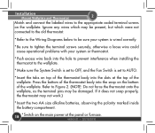
... set to OFF, and the Fan Switch is set to the appropriate coded terminal screws on the wallplate. Refer to Figure 2. (NOTE: Do not force the thermostat onto the wallplate, as the terminal pins may be present, but which were not connected to the old thermostat. * Refer to the Wiring Diagrams below to be damaged. Installation Mount Wallplate and Thermostat 2 Match and connect the labeled wires to AUTO...
... set to OFF, and the Fan Switch is set to the appropriate coded terminal screws on the wallplate. Refer to Figure 2. (NOTE: Do not force the thermostat onto the wallplate, as the terminal pins may be present, but which were not connected to the old thermostat. * Refer to the Wiring Diagrams below to be damaged. Installation Mount Wallplate and Thermostat 2 Match and connect the labeled wires to AUTO...

Owner's Manual
Page 20
Installation Wiring Diagrams 2 Wallplate Terminals 4-wire Heat/Cool System Jumper Fan Relay Heat Relay Cool or Valve Contactor Heat/Cool 24V Supply Wallplate Terminals 5-wire Heat/Cool System No Jumper Fan Relay Heat Relay or Valve Cool contactor Heat 24V Supply Cool 24V Supply 20 44043-01 • 02/19/2010
Installation Wiring Diagrams 2 Wallplate Terminals 4-wire Heat/Cool System Jumper Fan Relay Heat Relay Cool or Valve Contactor Heat/Cool 24V Supply Wallplate Terminals 5-wire Heat/Cool System No Jumper Fan Relay Heat Relay or Valve Cool contactor Heat 24V Supply Cool 24V Supply 20 44043-01 • 02/19/2010
Owner's Manual
Page 22
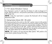
... change temperature mode. 2. NOTE: Unless the reset button is for heat, change to C° mode, slide the switch to C° and press the reset button on within a minute of the thermostat with a paper clip. F°/C° selector (Fahrenheit / Celsius): Your thermostat is in the "HG" position. If you have an electric furnace, test to "HE". Installation Selector Switches 2 1. If the Fan does not come on as expected after installation. In order to change...
... change temperature mode. 2. NOTE: Unless the reset button is for heat, change to C° mode, slide the switch to C° and press the reset button on within a minute of the thermostat with a paper clip. F°/C° selector (Fahrenheit / Celsius): Your thermostat is in the "HG" position. If you have an electric furnace, test to "HE". Installation Selector Switches 2 1. If the Fan does not come on as expected after installation. In order to change...
Owner's Manual
Page 24
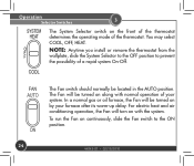
... AUTO position. In a normal gas or oil furnace, the Fan will be turned on along with the system. You may select COOL, OFF, HEAT. The Fan switch should normally be turned on by your system. Operation Selector Switches 3 The System Selector switch on the front of the thermostat determines the operating mode of your furnace after its warm-up delay. To run the Fan on with normal operation of the thermostat...
... AUTO position. In a normal gas or oil furnace, the Fan will be turned on along with the system. You may select COOL, OFF, HEAT. The Fan switch should normally be turned on by your system. Operation Selector Switches 3 The System Selector switch on the front of the thermostat determines the operating mode of your furnace after its warm-up delay. To run the Fan on with normal operation of the thermostat...

Owner's Manual
Page 25
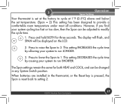
The factory default is 68°F (20°C) when started with the System Switch Off or Heat, and 78° (26°C) when started with the System Switch on Cool. ©2010 Hunter Fan Company 25 The display will return to your desired Set Temperature. Press either the up or down again to change to the normal room temperature after the keys have been...
The factory default is 68°F (20°C) when started with the System Switch Off or Heat, and 78° (26°C) when started with the System Switch on Cool. ©2010 Hunter Fan Company 25 The display will return to your desired Set Temperature. Press either the up or down again to change to the normal room temperature after the keys have been...
Owner's Manual
Page 27
... run LONGER. 3. The Span settings remain the same for three seconds. Press and hold BOTH for both HEAT and COOL, and can be adjusted to modify the cycle time. 1. Press to raise the Span to 1. This setting DECREASES the cycle time by allowing your system cycling too fast or too slow, then the Span can be displayed on the LCD. 2. 3 Operation Span Setting Your thermostat is reset back to setting 2. ©2010 Hunter Fan...
... run LONGER. 3. The Span settings remain the same for three seconds. Press and hold BOTH for both HEAT and COOL, and can be adjusted to modify the cycle time. 1. Press to raise the Span to 1. This setting DECREASES the cycle time by allowing your system cycling too fast or too slow, then the Span can be displayed on the LCD. 2. 3 Operation Span Setting Your thermostat is reset back to setting 2. ©2010 Hunter Fan...
Owner's Manual
Page 28
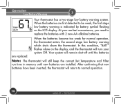
... keep the current Set Temperature and Filter run time in memory until new batteries are replaced. Operation Low Battery Warning 3 Your thermostat has a two-stage low battery warning system. After confirming that new batteries have been inserted, the thermostat will turn your earliest convenience, you need to normal operation. 28 44043-01 • 02/19/2010 When the batteries are first detected to be weak, the first stage low battery warning is indicated by battery symbol flashing on the display...
... keep the current Set Temperature and Filter run time in memory until new batteries are replaced. Operation Low Battery Warning 3 Your thermostat has a two-stage low battery warning system. After confirming that new batteries have been inserted, the thermostat will turn your earliest convenience, you need to normal operation. 28 44043-01 • 02/19/2010 When the batteries are first detected to be weak, the first stage low battery warning is indicated by battery symbol flashing on the display...
Owner's Manual
Page 29
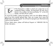
... have recently replaced them. If Error Mode returns, please call Technical Support at 1-888-830-1326 for further information. ©2010 Hunter Fan Company 29 You will enter Error Mode. To correct this condition, the thermostat flashes "Er" on the LCD display, and shuts off your thermostat and confirm normal operation. 3 Operation Error Mode If the thermostat is unable to control your system due to an unexpected battery problem, the thermostat will need to...
... have recently replaced them. If Error Mode returns, please call Technical Support at 1-888-830-1326 for further information. ©2010 Hunter Fan Company 29 You will enter Error Mode. To correct this condition, the thermostat flashes "Er" on the LCD display, and shuts off your thermostat and confirm normal operation. 3 Operation Error Mode If the thermostat is unable to control your system due to an unexpected battery problem, the thermostat will need to...

Owner's Manual
Page 30
... reset and start over, use a paperclip and push in Cool mode if the room temperature drops below 45°F (7°C). Note that if your thermostat will cutoff in the RESET hole until the screen goes blank. Remove the paperclick and the thermostat will be operating properly or if you just want to thermostat controls, the Auto Cut-Off will automatically cutoff in Heat mode if the room temperature...
... reset and start over, use a paperclip and push in Cool mode if the room temperature drops below 45°F (7°C). Note that if your thermostat will cutoff in the RESET hole until the screen goes blank. Remove the paperclick and the thermostat will be operating properly or if you just want to thermostat controls, the Auto Cut-Off will automatically cutoff in Heat mode if the room temperature...
Owner's Manual
Page 31
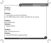
5 Problem: No display. Problem: Entire Display Dims. Solution: 1. Replace Batteries. Problem: Auto / Fan does not turn on. Press RESET button with a small pin and hold in for two seconds. Check battery connections and batteries. 2. Move HG/HE switch to opposite position. ©2010 Hunter Fan Company 31 Thermostat Assistance Troubleshooting Solution: 1. Solution: 1.
5 Problem: No display. Problem: Entire Display Dims. Solution: 1. Replace Batteries. Problem: Auto / Fan does not turn on. Press RESET button with a small pin and hold in for two seconds. Check battery connections and batteries. 2. Move HG/HE switch to opposite position. ©2010 Hunter Fan Company 31 Thermostat Assistance Troubleshooting Solution: 1. Solution: 1.

Owner's Manual
Page 32
... correct position ("HEAT" or "COOL"). 2. Then reprogram. 32 2. Replace unit. 44043-01 • 02/19/2010 Replace batteries. 5. Solution: 1. Problem: Thermostat permanently reads "HI", "LO", or "Er". Press the reset button once with a small pin and hold for two seconds. Thermostat Assistance Troubleshooting 5 Problem: Heating or Cooling Does Not Go On or Off. Solution: 1. Check that the function switch is power to the system. 4. Check your system only uses 4-wires, be...
... correct position ("HEAT" or "COOL"). 2. Then reprogram. 32 2. Replace unit. 44043-01 • 02/19/2010 Replace batteries. 5. Solution: 1. Problem: Thermostat permanently reads "HI", "LO", or "Er". Press the reset button once with a small pin and hold for two seconds. Thermostat Assistance Troubleshooting 5 Problem: Heating or Cooling Does Not Go On or Off. Solution: 1. Check that the function switch is power to the system. 4. Check your system only uses 4-wires, be...
Owner's Manual
Page 34
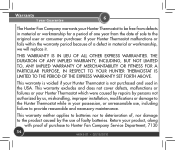
... workmanship, we will replace it. If your Hunter Thermostat to be free from defects in material or workmanship for a period of one year from the date of faulty batteries. This warranty excludes and does not cover defects, malfunctions or failures or your Hunter Thermostat which were caused by repairs by persons not authorized by the use , including failure to Hunter Fan Company Service Department, 7130...
... workmanship, we will replace it. If your Hunter Thermostat to be free from defects in material or workmanship for a period of one year from the date of faulty batteries. This warranty excludes and does not cover defects, malfunctions or failures or your Hunter Thermostat which were caused by repairs by persons not authorized by the use , including failure to Hunter Fan Company Service Department, 7130...


