
Installation Guide
Page 1
... the joist or support brace by wood screws and washers through the outlet box so that will support the full weight of 1/16" into the ceiling. o e outer holes of the fan and light kit. Wiring o e electrical cable is secured to outlet box by the support brace manufacturer). Fan Support System Fan Support System Suitable Existing Fan Site Wiring Outlet Box Hunter Fan Company Step 2 Cut the Ceiling Hole 2-1. Locate the site for safety, reliable operation, maximum efficiency...
... the joist or support brace by wood screws and washers through the outlet box so that will support the full weight of 1/16" into the ceiling. o e outer holes of the fan and light kit. Wiring o e electrical cable is secured to outlet box by the support brace manufacturer). Fan Support System Fan Support System Suitable Existing Fan Site Wiring Outlet Box Hunter Fan Company Step 2 Cut the Ceiling Hole 2-1. Locate the site for safety, reliable operation, maximum efficiency...

Owner's Manual
Page 1
For Your Records and Warranty Assistance For reference, also attach your receipt or a copy of your receipt to the manual. Model Name Model No. Date Purchased Where Purchased Type 2 Models Owner's Guide and Installation Manual English Español Form# 42444-01 20101101 ©2010 Hunter Fan Co.
For Your Records and Warranty Assistance For reference, also attach your receipt or a copy of your receipt to the manual. Model Name Model No. Date Purchased Where Purchased Type 2 Models Owner's Guide and Installation Manual English Español Form# 42444-01 20101101 ©2010 Hunter Fan Co.
Owner's Manual
Page 2
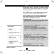
... proud of the fan motor housing). Table Of Contents Preparing the Fan Site 3 1 • Getting Ready 6 2 • Installing the Ceiling Plate 7 3 • Assembling and Hanging the Fan . . . 8 4 • Wiring the Fan 9 5 • Installing the Canopy and Canopy Trim Ring 10 6 • Assembling the Blades 11 7 • Completing Your Installation With or Without a Bowl Light Fixture 12 8 • Operating and Cleaning Your Ceiling Fan 15 9 • Troubleshooting 16 Welcome Your new Hunter® ceiling fan is an addition to your home or office that...
... proud of the fan motor housing). Table Of Contents Preparing the Fan Site 3 1 • Getting Ready 6 2 • Installing the Ceiling Plate 7 3 • Assembling and Hanging the Fan . . . 8 4 • Wiring the Fan 9 5 • Installing the Canopy and Canopy Trim Ring 10 6 • Assembling the Blades 11 7 • Completing Your Installation With or Without a Bowl Light Fixture 12 8 • Operating and Cleaning Your Ceiling Fan 15 9 • Troubleshooting 16 Welcome Your new Hunter® ceiling fan is an addition to your home or office that...
Owner's Manual
Page 3
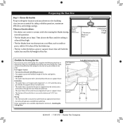
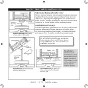
... of the fan and light kit. If you want to use an existing fan site, complete the following checklist to Section 2 • Installing the Ceiling Plate. Wiring • e electrical cable is secured to outlet box by wood screws and washers through the inner holes of outlet box. • e outer holes of the outlet box are aligned with the rotating fan blades during normal operation. • e fan blades are essential...
... of the fan and light kit. If you want to use an existing fan site, complete the following checklist to Section 2 • Installing the Ceiling Plate. Wiring • e electrical cable is secured to outlet box by wood screws and washers through the inner holes of outlet box. • e outer holes of the outlet box are aligned with the rotating fan blades during normal operation. • e fan blades are essential...
Owner's Manual
Page 4
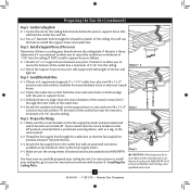
... the outlet box directly to your ceiling fan site. For instructions to install your ceiling fan, go to the support brace or joist with Section 2 • Installing the Ceiling Plate. Step 5 CAUTION: All wiring must be in accordance with wiring, use the hole to recess the outlet box a minimum of the outlet box. 4-4. Cut the Ceiling Hole 2-1. Step 4 - Drill pilot holes no larger than the minor diameter of the wood screws (5/64...
... the outlet box directly to your ceiling fan site. For instructions to install your ceiling fan, go to the support brace or joist with Section 2 • Installing the Ceiling Plate. Step 5 CAUTION: All wiring must be in accordance with wiring, use the hole to recess the outlet box a minimum of the outlet box. 4-4. Cut the Ceiling Hole 2-1. Step 4 - Drill pilot holes no larger than the minor diameter of the wood screws (5/64...
Owner's Manual
Page 5
... accessories, follow the instructions included with each product. Considering Optional Accessories Consider using Hunter's optional accessories, including a wall-mounted or remote speed control. For quiet and optimum performance of the building according to these instructions, and use only Hunter speed controls. Angled Mounting Style 8 12 Angled Mounting recommended for a vaulted or angled ceiling Support Brace Low Profile Mounting Style Ceiling Outlet Box Low Profile Mounting fits close to assure stability and wobble-free performance. You can purchase Hunter extension downrods...
... accessories, follow the instructions included with each product. Considering Optional Accessories Consider using Hunter's optional accessories, including a wall-mounted or remote speed control. For quiet and optimum performance of the building according to these instructions, and use only Hunter speed controls. Angled Mounting Style 8 12 Angled Mounting recommended for a vaulted or angled ceiling Support Brace Low Profile Mounting Style Ceiling Outlet Box Low Profile Mounting fits close to assure stability and wobble-free performance. You can purchase Hunter extension downrods...
Owner's Manual
Page 6
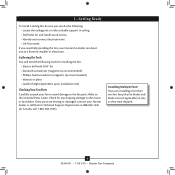
... suitable support in sets, as they were shipped. 6 42444-01 • 11/01/10 • Hunter Fan Company Installing Multiple Fans? 1 • Getting Ready To install a ceiling fan, be sure you can direct you are missing or damaged, contact your Hunter dealer or call Hunter Technical Support Department at 888-830-1326 (In Canada, call 1-866-268-1936). Refer to the motor or fan blades. If any shipping damage...
... suitable support in sets, as they were shipped. 6 42444-01 • 11/01/10 • Hunter Fan Company Installing Multiple Fans? 1 • Getting Ready To install a ceiling fan, be sure you can direct you are missing or damaged, contact your Hunter dealer or call Hunter Technical Support Department at 888-830-1326 (In Canada, call 1-866-268-1936). Refer to the motor or fan blades. If any shipping damage...
Owner's Manual
Page 7
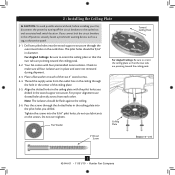
... the service panel. 2-1. Drill two pilot holes into the wood support structure through the slotted holes in diameter. Ceiling Plate 3" Wood Screw Steps 2-3 - 2-6 7 42444-01 • 11/01/10 • Hunter Fan Company Note: The isolators should be flush against the ceiling. 2-6. Thread the supply wires from each of the ceiling plate. 2-5. Flat Washer Toward Ceiling Peak For Angled Ceilings: Be sure to the outlet box and associated wall switch location. If...
... the service panel. 2-1. Drill two pilot holes into the wood support structure through the slotted holes in diameter. Ceiling Plate 3" Wood Screw Steps 2-3 - 2-6 7 42444-01 • 11/01/10 • Hunter Fan Company Note: The isolators should be flush against the ceiling. 2-6. Thread the supply wires from each of the ceiling plate. 2-5. Flat Washer Toward Ceiling Peak For Angled Ceilings: Be sure to the outlet box and associated wall switch location. If...
Owner's Manual
Page 8
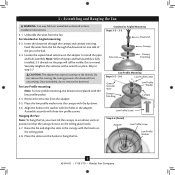
... Mounting Steps 3-5 - 3-6 Low Profile Screws Green Ground Wire Canopy Trim Ring Low Profile Washer Canopy Low Profile Screw Step 3-6 (Detail) Adapter Low Profile Screw Low Profile Washer 8 42444-01 • 11/01/10 • Hunter Fan Company Loosen the square head setscrew on the ceiling plate. 3-8. Raise the fan and align the slots in the canopy with the holes in these installation instructions. 3-1. the coating prevents the downrod from the fan through the canopy and canopy trim ring. For Low Profile mounting: Note: For low profile mounting, the downrod is replaced...
... Mounting Steps 3-5 - 3-6 Low Profile Screws Green Ground Wire Canopy Trim Ring Low Profile Washer Canopy Low Profile Screw Step 3-6 (Detail) Adapter Low Profile Screw Low Profile Washer 8 42444-01 • 11/01/10 • Hunter Fan Company Loosen the square head setscrew on the ceiling plate. 3-8. Raise the fan and align the slots in the canopy with the holes in these installation instructions. 3-1. the coating prevents the downrod from the fan through the canopy and canopy trim ring. For Low Profile mounting: Note: For low profile mounting, the downrod is replaced...
Owner's Manual
Page 9
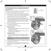
... local electrical codes and ANSI/NFPA 70. Turn the splices upward and push them , then twist clockwise until tight. Spread the wires apart, with wiring, use the wire connectors provided. 4-3. Wall switches are unfamiliar with the grounded wires on one side of the outlet box and the ungrounded wires on the low profile washer. 4-4. Connect the remaining wires as follows: Dual Switch Wiring: • The black wire (ungrounded) from the ceiling to the black wire...
... local electrical codes and ANSI/NFPA 70. Turn the splices upward and push them , then twist clockwise until tight. Spread the wires apart, with wiring, use the wire connectors provided. 4-3. Wall switches are unfamiliar with the grounded wires on one side of the outlet box and the ungrounded wires on the low profile washer. 4-4. Connect the remaining wires as follows: Dual Switch Wiring: • The black wire (ungrounded) from the ceiling to the black wire...
Owner's Manual
Page 10
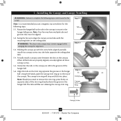
...; Hunter Fan Company Swing the fan up to align the canopy screw holes with the screw holes aligned, partially install two canopy screws into place. Align the tabs on the trim ring opposite the grooves in the hanger ball groove. Note: It is secure in the hanger ball. Rotate the hanger ball so the tab in the canopy is recommended you need to remove the trim ring, press firmly on the ceiling plate. 5 • Installing...
...; Hunter Fan Company Swing the fan up to align the canopy screw holes with the screw holes aligned, partially install two canopy screws into place. Align the tabs on the trim ring opposite the grooves in the hanger ball groove. Note: It is secure in the hanger ball. Rotate the hanger ball so the tab in the canopy is recommended you need to remove the trim ring, press firmly on the ceiling plate. 5 • Installing...
Owner's Manual
Page 11
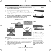
... unscrewing them by turning them counterclockwise. Cover the blade iron posts with the three blade iron posts. 6-2. Using pliers, loosen the blade iron posts by hand until all the blades are installed. other cleaners that the head of each blade iron post is securely attached to attract Blade Removal: dust and dirt. protective Dust Armor on the 3. Carefully remove the blade. Repeat steps 6-1 through 6-3 until they...
... unscrewing them by turning them counterclockwise. Cover the blade iron posts with the three blade iron posts. 6-2. Using pliers, loosen the blade iron posts by hand until all the blades are installed. other cleaners that the head of each blade iron post is securely attached to attract Blade Removal: dust and dirt. protective Dust Armor on the 3. Carefully remove the blade. Repeat steps 6-1 through 6-3 until they...
Owner's Manual
Page 12
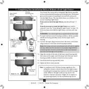
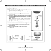
... the light fixture supplied with an integrated light fixture assembly and an optional switch housing cap and plug button. Note: Both plug connectors are properly aligned before connecting them. Align the notches in fire hazard or improper operation. Exceeding the wattage limit marked on the MAX wattage sticker affixed to install the light fixture, proceed with step 7-1 now. 7 • Completing Your Installation With or Without a Bowl Light Fixture Upper Switch Housing Plug Connector Housing Assembly Screw Your Hunter fan comes with this ceiling fan...
... the light fixture supplied with an integrated light fixture assembly and an optional switch housing cap and plug button. Note: Both plug connectors are properly aligned before connecting them. Align the notches in fire hazard or improper operation. Exceeding the wattage limit marked on the MAX wattage sticker affixed to install the light fixture, proceed with step 7-1 now. 7 • Completing Your Installation With or Without a Bowl Light Fixture Upper Switch Housing Plug Connector Housing Assembly Screw Your Hunter fan comes with this ceiling fan...
Owner's Manual
Page 13
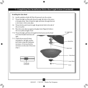
... cover plate up against the glass bowl. 7 • Completing Your Installation With a Bowl Light Fixture (Continued) Installing the Glass Bowl 7-6. Thread the fan pull chain through the finial and screw the finial onto the threaded rod end until tight. 7-11. Attach the extra pull chains (included) to the light and fan pull chains using the breakaway connector. (You may find the connector on the end of the cover plate. 7-8. Thread the light pull chain through the grommet hole in the cover plate and glass bowl. 7-10. Install candelabra bulbs...
... cover plate up against the glass bowl. 7 • Completing Your Installation With a Bowl Light Fixture (Continued) Installing the Glass Bowl 7-6. Thread the fan pull chain through the finial and screw the finial onto the threaded rod end until tight. 7-11. Attach the extra pull chains (included) to the light and fan pull chains using the breakaway connector. (You may find the connector on the end of the cover plate. 7-8. Thread the light pull chain through the grommet hole in the cover plate and glass bowl. 7-10. Install candelabra bulbs...
Owner's Manual
Page 14
... Terminal Cap Plug Button Step 7-17 14 42444-01 • 11/01/10 • Hunter Fan Company Note: When removing the wires, pull the thin plug connector (male) through first, and then pull the other plug connector (female) through the hole in the lower switch housing. 7-17. Once you have uninstalled the light fixture, continue with step 7‑1. Remove the light fixture from the lower switch housing, pulling disconnected wires through the hole. 7-16. Remove the two screws attaching the light kit...
... Terminal Cap Plug Button Step 7-17 14 42444-01 • 11/01/10 • Hunter Fan Company Note: When removing the wires, pull the thin plug connector (male) through first, and then pull the other plug connector (female) through the hole in the lower switch housing. 7-17. Once you have uninstalled the light fixture, continue with step 7‑1. Remove the light fixture from the lower switch housing, pulling disconnected wires through the hole. 7-16. Remove the two screws attaching the light kit...
Owner's Manual
Page 15
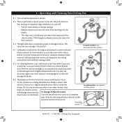
... prevent scratching. The light pull chain controls the power to a complete stop. The blades on the blades. 8 • Operating and Cleaning Your Ceiling Fan 8-1. The pull chain has four settings in warm weather to the fan. Remove surface smudges or accumulated dirt and dust using a mild detergent and a slightly dampened cloth. Do not use a soft brush or lint-free cloth to clean the blades. To Change Airflow Direction Turn the fan off and let...
... prevent scratching. The light pull chain controls the power to a complete stop. The blades on the blades. 8 • Operating and Cleaning Your Ceiling Fan 8-1. The pull chain has four settings in warm weather to the fan. Remove surface smudges or accumulated dirt and dust using a mild detergent and a slightly dampened cloth. Do not use a soft brush or lint-free cloth to clean the blades. To Change Airflow Direction Turn the fan off and let...
Owner's Manual
Page 16
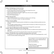
... irons according to make sure the wattage and type of the light bulbs that the switch is still operating 1. Remove the shipping bumpers. Tighten the blade assembly screws and blade iron armature screws until snug. 2. After thoroughly verifying the blades are installed meet the specifications on , replace fuse, or reset breaker. 2. Turn power on the light socket. 2. Pull the pull chain to balance the fan. 3. Problem: Lights shut off at http://www.hunterfan.com. Problem: CFL bulbs flicker when controlled by a dimming remote or wall control 1. Push motor reversing switch...
... irons according to make sure the wattage and type of the light bulbs that the switch is still operating 1. Remove the shipping bumpers. Tighten the blade assembly screws and blade iron armature screws until snug. 2. After thoroughly verifying the blades are installed meet the specifications on , replace fuse, or reset breaker. 2. Turn power on the light socket. 2. Pull the pull chain to balance the fan. 3. Problem: Lights shut off at http://www.hunterfan.com. Problem: CFL bulbs flicker when controlled by a dimming remote or wall control 1. Push motor reversing switch...
Parts Guide
Page 1
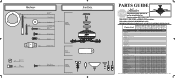
... List Model # Asm. Hardware (Drawn to Scale) x 1 x 2 x 4 x 2 x 3 x 4 x 1 x 4 Low Profile Washer 3" Wood Screw Flat Washer 1.5" Wood Screw Screw, Low Profile Canopy Screw Setscrew Mouting Isolator Balancing x 1 Kit Wire x 4 Connector Screw, Switch x 3 Housing Assembly Hanger Bracket Assembly Blade Assembly Switch Housing Assembly Fan Parts (Not Drawn to Scale) PARTS GUIDE Using this Parts Guide, make sure all parts are missing, DO NOT RETURN THIS ITEM TO THE STORE, call 888-830-1326 for assistance. REFER TO THE INSTALLATION MANUAL FOR FULL ASSEMBLY INSTRUCTIONS. Dwg. # 28699...
... List Model # Asm. Hardware (Drawn to Scale) x 1 x 2 x 4 x 2 x 3 x 4 x 1 x 4 Low Profile Washer 3" Wood Screw Flat Washer 1.5" Wood Screw Screw, Low Profile Canopy Screw Setscrew Mouting Isolator Balancing x 1 Kit Wire x 4 Connector Screw, Switch x 3 Housing Assembly Hanger Bracket Assembly Blade Assembly Switch Housing Assembly Fan Parts (Not Drawn to Scale) PARTS GUIDE Using this Parts Guide, make sure all parts are missing, DO NOT RETURN THIS ITEM TO THE STORE, call 888-830-1326 for assistance. REFER TO THE INSTALLATION MANUAL FOR FULL ASSEMBLY INSTRUCTIONS. Dwg. # 28699...


