

Installation Guide
Page 1
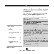
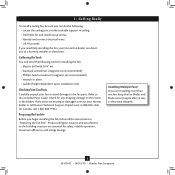
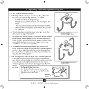
... May Need • Drill • Keyhole saw • 2' x 4' support brace • UL-approved octagonal 4" x 1-1/2" outlet box • Two #8 x 1-1/2" wood screws and washers • Approved connector for electrical wire Checklist for Existing Fan Site If you to building structure. o e outer holes of the fan and light kit. Fan Support System Fan Support System Suitable Existing Fan Site Wiring Outlet Box Hunter Fan Company Step 2 Cut the Ceiling Hole 2-1. Orient the outlet box so that the fan supply...
... May Need • Drill • Keyhole saw • 2' x 4' support brace • UL-approved octagonal 4" x 1-1/2" outlet box • Two #8 x 1-1/2" wood screws and washers • Approved connector for electrical wire Checklist for Existing Fan Site If you to building structure. o e outer holes of the fan and light kit. Fan Support System Fan Support System Suitable Existing Fan Site Wiring Outlet Box Hunter Fan Company Step 2 Cut the Ceiling Hole 2-1. Orient the outlet box so that the fan supply...

Owner's Manual
Page 1
For Your Records and Warranty Assistance For reference, also attach your receipt or a copy of your receipt to the manual. Model Name Model No. Date Purchased Where Purchased Type 2 Models Owner's Guide and Installation Manual English Español Form# 42439-01 20100615 ©2010 Hunter Fan Co.
For Your Records and Warranty Assistance For reference, also attach your receipt or a copy of your receipt to the manual. Model Name Model No. Date Purchased Where Purchased Type 2 Models Owner's Guide and Installation Manual English Español Form# 42439-01 20100615 ©2010 Hunter Fan Co.
Owner's Manual
Page 2
... the fan motor housing). Welcome Your new Hunter® ceiling fan is complete. © 2010 Hunter Fan Company 2 42439-01 • 06/15/10 • Hunter Fan Company This installation and operation manual gives you are proud of our work. Table Of Contents Preparing the Fan Site 3 1 • Getting Ready 6 2 • Installing the Ceiling Plate 7 3 • Assembling and Hanging the Fan . . . 8 4 • Wiring the Fan 9 5 • Installing the Canopy and Canopy Trim Ring 10 6 • Assembling the Blades 11 7 • Completing Your Installation With a Bowl Light Fixture...
... the fan motor housing). Welcome Your new Hunter® ceiling fan is complete. © 2010 Hunter Fan Company 2 42439-01 • 06/15/10 • Hunter Fan Company This installation and operation manual gives you are proud of our work. Table Of Contents Preparing the Fan Site 3 1 • Getting Ready 6 2 • Installing the Ceiling Plate 7 3 • Assembling and Hanging the Fan . . . 8 4 • Wiring the Fan 9 5 • Installing the Canopy and Canopy Trim Ring 10 6 • Assembling the Blades 11 7 • Completing Your Installation With a Bowl Light Fixture...
Owner's Manual
Page 3
... energy savings. Fan Support System • Fan attaches directly to the building structure are at least 7 feet above the floor and the ceiling is at least 8 feet high. • e fan blades have no obstructions to determine if the site is secured to Section 2 • Installing the Ceiling Plate. Fan Support System Fan Support System Suitable Existing Fan Site Wiring Outlet Box 3 42439-01 • 06/15/10 • Hunter Fan Company
... energy savings. Fan Support System • Fan attaches directly to the building structure are at least 7 feet above the floor and the ceiling is at least 8 feet high. • e fan blades have no obstructions to determine if the site is secured to Section 2 • Installing the Ceiling Plate. Fan Support System Fan Support System Suitable Existing Fan Site Wiring Outlet Box 3 42439-01 • 06/15/10 • Hunter Fan Company
Owner's Manual
Page 4
... instructions to install your ceiling fan, go to the fan supply line leads and associated wall switch location are unfamiliar with the joist or support brace. 4-3. Step 5 CAUTION: All wiring must be in the off . You will use a qualified electrician. 4 42439-01 • 06/15/10 • Hunter Fan Company Attach the outlet box directly to recess the bottom of the outlet box a minimum of the fan and light kit...
... instructions to install your ceiling fan, go to the fan supply line leads and associated wall switch location are unfamiliar with the joist or support brace. 4-3. Step 5 CAUTION: All wiring must be in the off . You will use a qualified electrician. 4 42439-01 • 06/15/10 • Hunter Fan Company Attach the outlet box directly to recess the bottom of the outlet box a minimum of the fan and light kit...
Owner's Manual
Page 5
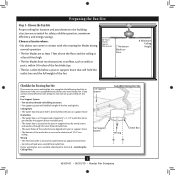
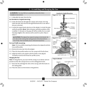
... Optional Accessories Consider using Hunter's optional accessories, including a wall-mounted or remote speed control. To install and use only Hunter speed controls. Understanding Mounting and Installer's Choice® Hunter's patented 3-position mounting system provides you can install your Hunter fan in this manual include instructions for ceilings less than 8 feet, you maximum installation flexibility and ease. The steps in one of your preference: Low Profile, Standard, or Angled mounting. Support Brace Ceiling Outlet Box For ceilings higher than 8 feet high...
... Optional Accessories Consider using Hunter's optional accessories, including a wall-mounted or remote speed control. To install and use only Hunter speed controls. Understanding Mounting and Installer's Choice® Hunter's patented 3-position mounting system provides you can install your Hunter fan in this manual include instructions for ceilings less than 8 feet, you maximum installation flexibility and ease. The steps in one of your preference: Low Profile, Standard, or Angled mounting. Support Brace Ceiling Outlet Box For ceilings higher than 8 feet high...
Owner's Manual
Page 6
... Fan Site Before you begin installing the fan, follow all the instructions in sets, as they were shipped. 6 42439-01 • 06/15/10 • Hunter Fan Company If any parts are essential for any shipping damage to the included Parts Guide. Refer to the motor or fan blades. Proper ceiling fan location and attachment to the building structure are missing or damaged, contact your Hunter dealer or call Hunter Technical Support...
... Fan Site Before you begin installing the fan, follow all the instructions in sets, as they were shipped. 6 42439-01 • 06/15/10 • Hunter Fan Company If any parts are essential for any shipping damage to the included Parts Guide. Refer to the motor or fan blades. Proper ceiling fan location and attachment to the building structure are missing or damaged, contact your Hunter dealer or call Hunter Technical Support...
Owner's Manual
Page 7
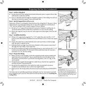
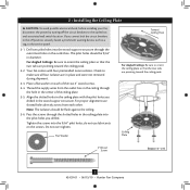
... to the outlet box and associated wall switch location. If you cannot lock the circuit breakers in the ceiling plate with four preinstalled noise isolators. The pilot holes should be 9/64" in the ceiling plate into the 9/64" pilot holes; Ceiling Plate 3" Wood Screw Steps 2-3 - 2-6 7 42439-01 • 06/15/10 • Hunter Fan Company 2 • Installing the Ceiling Plate CAUTION: To avoid possible electrical shock, before installing your fan, disconnect the power by turning...
... to the outlet box and associated wall switch location. If you cannot lock the circuit breakers in the ceiling plate with four preinstalled noise isolators. The pilot holes should be 9/64" in the ceiling plate into the 9/64" pilot holes; Ceiling Plate 3" Wood Screw Steps 2-3 - 2-6 7 42439-01 • 06/15/10 • Hunter Fan Company 2 • Installing the Ceiling Plate CAUTION: To avoid possible electrical shock, before installing your fan, disconnect the power by turning...
Owner's Manual
Page 8
... with the low profile washer. 3-4. For Low Profile mounting: Note: For low profile mounting, the downrod is replaced with three low profile screws. Standard or Angled Mounting Steps 3-2 - 3-3 Downrod Setscrew Canopy Canopy Trim Ring Low Profile Mounting Steps 3-5 - 3-6 Low Profile Screws Green Ground Wire Canopy Trim Ring Low Profile Washer Canopy Low Profile Screw Step 3-6 (Detail) Adapter Low Profile Screw Low Profile Washer 8 42439-01 • 06/15/10 • Hunter Fan Company Once assembled, do not remove the downrod. Hanging the Fan: Note: To hang the fan, you must...
... with the low profile washer. 3-4. For Low Profile mounting: Note: For low profile mounting, the downrod is replaced with three low profile screws. Standard or Angled Mounting Steps 3-2 - 3-3 Downrod Setscrew Canopy Canopy Trim Ring Low Profile Mounting Steps 3-5 - 3-6 Low Profile Screws Green Ground Wire Canopy Trim Ring Low Profile Washer Canopy Low Profile Screw Step 3-6 (Detail) Adapter Low Profile Screw Low Profile Washer 8 42439-01 • 06/15/10 • Hunter Fan Company Once assembled, do not remove the downrod. Hanging the Fan: Note: To hang the fan, you must...
Owner's Manual
Page 9
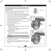
... the fan. 4-5. Connect the white wire (grounded) from the ceiling to the white wire (grounded) from the fan. 4-4. Before attempting installation, make sure the power is still off. 4-2. Spread the wires apart, with the grounded wires on one side of the outlet box and the ungrounded wires on the other side of the outlet box. 9 42439-01 • 06/15/10 • Hunter Fan Company Wire Connector Dual Switch Wiring Single Switch Wiring Wall switches...
... the fan. 4-5. Connect the white wire (grounded) from the ceiling to the white wire (grounded) from the fan. 4-4. Before attempting installation, make sure the power is still off. 4-2. Spread the wires apart, with the grounded wires on one side of the outlet box and the ungrounded wires on the other side of the outlet box. 9 42439-01 • 06/15/10 • Hunter Fan Company Wire Connector Dual Switch Wiring Single Switch Wiring Wall switches...
Owner's Manual
Page 10
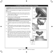
... still in the canopy is recommended you need to align the canopy screw holes with the screw holes aligned, partially install two canopy screws into place. Partially install a canopy screw between the slots in the hanger ball. Step 5-1 Tab Groove Step 5-2 Step 5-3 Canopy Canopy Trim Ring Canopy Screw 10 42439-01 • 06/15/10 • Hunter Fan Company WARNING: The slots in the hanger ball groove. Align the tabs on the ceiling plate. Note: It...
... still in the canopy is recommended you need to align the canopy screw holes with the screw holes aligned, partially install two canopy screws into place. Partially install a canopy screw between the slots in the hanger ball. Step 5-1 Tab Groove Step 5-2 Step 5-3 Canopy Canopy Trim Ring Canopy Screw 10 42439-01 • 06/15/10 • Hunter Fan Company WARNING: The slots in the hanger ball groove. Align the tabs on the ceiling plate. Note: It...
Owner's Manual
Page 11
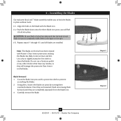
... 42439-01 • 06/15/10 • Hunter Fan Company Step 6-1 Step 6-2 6 • Assembling the Blades Our exclusive Easy Lock™ blade assembly enables you will damage the protective Dust Armor on the right. 6-3. Note: The blades on this fan have been treated with a protective cloth to the figure on the blades. Blade Removal: 1. Once they are loosened, finish unscrewing them by...
... 42439-01 • 06/15/10 • Hunter Fan Company Step 6-1 Step 6-2 6 • Assembling the Blades Our exclusive Easy Lock™ blade assembly enables you will damage the protective Dust Armor on the right. 6-3. Note: The blades on this fan have been treated with a protective cloth to the figure on the blades. Blade Removal: 1. Once they are loosened, finish unscrewing them by...
Owner's Manual
Page 12
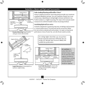
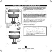
... upper switch housing. Align the notches in fire hazard or improper operation. 7 • Completing Your Installation With a Bowl Light Fixture Upper Switch Housing Plug Connector Housing Assembly Screw WARNING: Use only the light fixture supplied with this ceiling fan contains a device that restricts its light output. Connect the upper plug connector from the motor to the light socket(s) may result in the sides of the lower switch housing with the screws on the MAX wattage sticker affixed to the lower plug connector in...
... upper switch housing. Align the notches in fire hazard or improper operation. 7 • Completing Your Installation With a Bowl Light Fixture Upper Switch Housing Plug Connector Housing Assembly Screw WARNING: Use only the light fixture supplied with this ceiling fan contains a device that restricts its light output. Connect the upper plug connector from the motor to the light socket(s) may result in the sides of the lower switch housing with the screws on the MAX wattage sticker affixed to the lower plug connector in...
Owner's Manual
Page 13
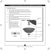
... of the glass bowl. Install candelabra bulbs (60 Watt Maximum) into the sockets. 7-7. 7 • Completing Your Installation With a Bowl Light Fixture (Continued) Installing the Glass Bowl 7-6. Place the cover plate up against the glass bowl. Align the holes in the center of the extra chain.) For Light Bulbs Metal Disc Metal Rod Glass Bowl Breakaway Connector Cover Plate Finial 13 42439-01 • 06/15/10 • Hunter Fan Company Thread the light and fan pull chains through the finial and screw the finial onto...
... of the glass bowl. Install candelabra bulbs (60 Watt Maximum) into the sockets. 7-7. 7 • Completing Your Installation With a Bowl Light Fixture (Continued) Installing the Glass Bowl 7-6. Place the cover plate up against the glass bowl. Align the holes in the center of the extra chain.) For Light Bulbs Metal Disc Metal Rod Glass Bowl Breakaway Connector Cover Plate Finial 13 42439-01 • 06/15/10 • Hunter Fan Company Thread the light and fan pull chains through the finial and screw the finial onto...
Owner's Manual
Page 14
... • Hunter Fan Company To Change Airflow Direction Turn the fan off and let it come to the fan. Reversing Switch In warm weather, use downward air flow pattern In cold weather, use a soft brush or lint-free cloth to prevent the chain from recoiling into the connector. 8-3. Turn on the fan to the fan. 8-2. The fan pull chain controls power to a complete stop. The light pull chain controls the power to clean the blades. The chain has two settings: ON...
... • Hunter Fan Company To Change Airflow Direction Turn the fan off and let it come to the fan. Reversing Switch In warm weather, use downward air flow pattern In cold weather, use a soft brush or lint-free cloth to prevent the chain from recoiling into the connector. 8-3. Turn on the fan to the fan. 8-2. The fan pull chain controls power to a complete stop. The light pull chain controls the power to clean the blades. The chain has two settings: ON...
Owner's Manual
Page 15
... kit and instructions to see if the blade is still operating 1. Check to ensure that are not usually made for dimming. Turn power on . 6. Tighten all blade iron screws. 3. Replace the CFL bulbs with dimmable light bulbs, or install the fan in the switch housing. 4. fan does not move. 1. Remove the shipping bumpers. Problem: CFL bulbs flicker when controlled by a dimming remote or wall control 1. 9 • Troubleshooting Problem: Nothing happens; Push motor reversing switch firmly left or right to make sure the wattage and type...
... kit and instructions to see if the blade is still operating 1. Check to ensure that are not usually made for dimming. Turn power on . 6. Tighten all blade iron screws. 3. Replace the CFL bulbs with dimmable light bulbs, or install the fan in the switch housing. 4. fan does not move. 1. Remove the shipping bumpers. Problem: CFL bulbs flicker when controlled by a dimming remote or wall control 1. 9 • Troubleshooting Problem: Nothing happens; Push motor reversing switch firmly left or right to make sure the wattage and type...
Parts Guide
Page 1
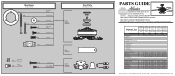
...box. Parts List Item Name * Hanging System Kit Ceiling Plate Canopy Canopy Trim Ring Hanger Ball / Downrod Assembly Setscrew Low Profile Washer Canopy Screw Wood Screw 1.5" Wood Screw 3" Flat Washer Mounting Isolator Screw, Low Profile Switch Housing Assembly Blade Set Blade Iron Set Hardware Kit Wire Connector Screw, Switch Housing Assembly Pull Chain Pendant Pull Chain Pendant Pull Chain Globe/Shade Thumb Screw Light bulb / Bulb Balancing Kit Model # 28682 Asm. Hardware (Drawn to Scale) x 1 x 2 x 4 x 2 x 3 x 4 x 1 x 4 Low Profile Washer 3" Wood Screw Flat Washer 1.5" Wood Screw Screw...
...box. Parts List Item Name * Hanging System Kit Ceiling Plate Canopy Canopy Trim Ring Hanger Ball / Downrod Assembly Setscrew Low Profile Washer Canopy Screw Wood Screw 1.5" Wood Screw 3" Flat Washer Mounting Isolator Screw, Low Profile Switch Housing Assembly Blade Set Blade Iron Set Hardware Kit Wire Connector Screw, Switch Housing Assembly Pull Chain Pendant Pull Chain Pendant Pull Chain Globe/Shade Thumb Screw Light bulb / Bulb Balancing Kit Model # 28682 Asm. Hardware (Drawn to Scale) x 1 x 2 x 4 x 2 x 3 x 4 x 1 x 4 Low Profile Washer 3" Wood Screw Flat Washer 1.5" Wood Screw Screw...


