

Installation Guide
Page 1
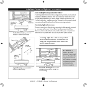
... rotating fan blades during normal operation. • e fan blades are unfamiliar with 2 • Installing the Ceiling Plate. If you want to the support brace or joist with an approved connector, available at least 6" beyond the box. 5-3. For instructions to install your ceiling fan, go to your new Hunter fan. Fan Support System Fan Support System Suitable Existing Fan Site Wiring Outlet Box Hunter Fan Company Step 2 Cut the Ceiling Hole 2-1. Attach a 2" x 4" support brace between two joists. o Fan support system will support the full weight...
... rotating fan blades during normal operation. • e fan blades are unfamiliar with 2 • Installing the Ceiling Plate. If you want to the support brace or joist with an approved connector, available at least 6" beyond the box. 5-3. For instructions to install your ceiling fan, go to your new Hunter fan. Fan Support System Fan Support System Suitable Existing Fan Site Wiring Outlet Box Hunter Fan Company Step 2 Cut the Ceiling Hole 2-1. Attach a 2" x 4" support brace between two joists. o Fan support system will support the full weight...

Owner's Manual
Page 2
... work. Before installing your fan, for many years. Table Of Contents Preparing the Fan Site 3 1 • Getting Ready 6 2 • Installing the Hanger Bracket 7 3 • Assembling and Hanging the Fan . . . . 8 4 •Wiring the Fan 10 5 • Installing the Canopy and Canopy Trim Ring 11 6 • Assembling the Blades 12 7 • Completing Your Installation With or Without a Bowl Light Fixture 13 8 • Operating and Cleaning Your Ceiling Fan 17 9 • Troubleshooting 18 Welcome Your new Hunter® ceiling fan is an addition to your home...
... work. Before installing your fan, for many years. Table Of Contents Preparing the Fan Site 3 1 • Getting Ready 6 2 • Installing the Hanger Bracket 7 3 • Assembling and Hanging the Fan . . . . 8 4 •Wiring the Fan 10 5 • Installing the Canopy and Canopy Trim Ring 11 6 • Assembling the Blades 12 7 • Completing Your Installation With or Without a Bowl Light Fixture 13 8 • Operating and Cleaning Your Ceiling Fan 17 9 • Troubleshooting 18 Welcome Your new Hunter® ceiling fan is an addition to your home...

Owner's Manual
Page 3
... inches of 1/16" into ceiling. Fan Support System Fan Support System Suitable Existing Fan Site Wiring Outlet Box 3 45065-01 • 11/05/09 • Hunter Fan Company Choose the Fan Site Proper ceiling fan location and attachment to airflow, such as described on this page. Fan Support System • Fan attaches directly to building structure. • Fan support system will hold full weight of the outlet box is at least 8 feet high. • e fan blades...
... inches of 1/16" into ceiling. Fan Support System Fan Support System Suitable Existing Fan Site Wiring Outlet Box 3 45065-01 • 11/05/09 • Hunter Fan Company Choose the Fan Site Proper ceiling fan location and attachment to airflow, such as described on this page. Fan Support System • Fan attaches directly to building structure. • Fan support system will hold full weight of the outlet box is at least 8 feet high. • e fan blades...

Owner's Manual
Page 4
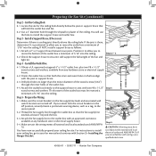
... wall switch location are unfamiliar with Section 2 • Installing the Hanger Bracket. If you to install the support brace and outlet box. Step 3 - Install a Support Brace, If Necessary Determine if there is positioned to allow you cannot lock the circuit breakers in the box align with two #8 x 1-1/2" Step 4 wood screws and washers. e bottom of the fan and light kit. If NOT, install a support brace as a tag, to the service...
... wall switch location are unfamiliar with Section 2 • Installing the Hanger Bracket. If you to install the support brace and outlet box. Step 3 - Install a Support Brace, If Necessary Determine if there is positioned to allow you cannot lock the circuit breakers in the box align with two #8 x 1-1/2" Step 4 wood screws and washers. e bottom of the fan and light kit. If NOT, install a support brace as a tag, to the service...
Owner's Manual
Page 5
... maximum installation flexibility and ease. Considering Optional Accessories Consider using Hunter's optional accessories, including a wall-mounted or remote speed control. The steps in one of three ways, depending on ceiling height and your Hunter fan, use only the hardware supplied. 5 45065-01 • 11/05/09 • Hunter Fan Company All Hunter fans use the accessories, follow the instructions included with each product. You can purchase Hunter extension downrods. Support Brace Ceiling Outlet Box For ceilings higher than 8 feet high CAUTION...
... maximum installation flexibility and ease. Considering Optional Accessories Consider using Hunter's optional accessories, including a wall-mounted or remote speed control. The steps in one of three ways, depending on ceiling height and your Hunter fan, use only the hardware supplied. 5 45065-01 • 11/05/09 • Hunter Fan Company All Hunter fans use the accessories, follow the instructions included with each product. You can purchase Hunter extension downrods. Support Brace Ceiling Outlet Box For ceilings higher than 8 feet high CAUTION...

Owner's Manual
Page 6
Proper ceiling fan location and attachment to the building structure are installing more than one fan, keep the fan blades and blade irons (if applicable) in sets, as they were shipped. 6 45065-01 • 11/05/09 • Hunter Fan Company Refer to the included Parts Guide. Installing Multiple Fans? If you begin installing the fan, follow all the instructions in ceiling. • Drill holes for and install wood screws. • Identify and connect electrical wires. • Lift 40...
Proper ceiling fan location and attachment to the building structure are installing more than one fan, keep the fan blades and blade irons (if applicable) in sets, as they were shipped. 6 45065-01 • 11/05/09 • Hunter Fan Company Refer to the included Parts Guide. Installing Multiple Fans? If you begin installing the fan, follow all the instructions in ceiling. • Drill holes for and install wood screws. • Identify and connect electrical wires. • Lift 40...

Owner's Manual
Page 7
...; Hunter Fan Company RIGHT do not use slotted holes directly across from the outlet box down through the slotted holes in the hanger bracket with four pre-installed neoprene noise isolators. Drill two pilot holes into the 9/64" pilot holes; Isolator Hanger Bracket 2-2. Align the slotted holes in the hanger bracket into the pilot holes you are installing the fan on an ANGLED ceiling, be flush against the ceiling. 2-4. Place a flat washer on the screws. Thread the lead wires...
...; Hunter Fan Company RIGHT do not use slotted holes directly across from the outlet box down through the slotted holes in the hanger bracket with four pre-installed neoprene noise isolators. Drill two pilot holes into the 9/64" pilot holes; Isolator Hanger Bracket 2-2. Align the slotted holes in the hanger bracket into the pilot holes you are installing the fan on an ANGLED ceiling, be flush against the ceiling. 2-4. Place a flat washer on the screws. Thread the lead wires...

Owner's Manual
Page 10
... these connections use switch in accordance with national and local electrical codes and ANSI/NFPA 70. Spread the wires apart, with the grounded wires on one side of the outlet box and the ungrounded wires on the low profile washer. 4-4. If you are not included. Connect the remaining wires as follows: Dual Switch Wiring: • The black wire (ungrounded) from the ceiling to the black wire (ungrounded) from the fan • The black/white wire...
... these connections use switch in accordance with national and local electrical codes and ANSI/NFPA 70. Spread the wires apart, with the grounded wires on one side of the outlet box and the ungrounded wires on the low profile washer. 4-4. If you are not included. Connect the remaining wires as follows: Dual Switch Wiring: • The black wire (ungrounded) from the ceiling to the black wire (ungrounded) from the fan • The black/white wire...

Owner's Manual
Page 13
... the Light Fixture" on step 7-15. Steps 7-1 - 7-3 Housing Assembly Screw Upper Switch Housing 13 45065-01 • 11/05/09 • Hunter Fan Company Align the keyhole slots in the narrow end of the housing. 7-3. Install the remaining screw into the switch housing mounting plate. 7-2. If you need to install the light fixture, proceed with an integrated light fixture assembly and an optional switch housing cap and plug button. Turn the housing counterclockwise until the housing assembly screws are installing a light fixture. WARNING: Use only the light fixture...
... the Light Fixture" on step 7-15. Steps 7-1 - 7-3 Housing Assembly Screw Upper Switch Housing 13 45065-01 • 11/05/09 • Hunter Fan Company Align the keyhole slots in the narrow end of the housing. 7-3. Install the remaining screw into the switch housing mounting plate. 7-2. If you need to install the light fixture, proceed with an integrated light fixture assembly and an optional switch housing cap and plug button. Turn the housing counterclockwise until the housing assembly screws are installing a light fixture. WARNING: Use only the light fixture...

Owner's Manual
Page 15
... the cover plate. 7-10. Then, thread the light pull chain through the grommet hole in the side of 190 Watts. Attach the extra pull chains (included) to be operating properly, see the troubleshooting section Breakaway Connector Light Bulb Socket (B10 Candelabra Based 60 Watt Maximum) Metal Disc Threaded Rod Glass Bowl Cover Plate Finial 15 45065-01 • 11/05/09 • Hunter Fan Company Thread the light and fan pull chains through the finial and screw the finial...
... the cover plate. 7-10. Then, thread the light pull chain through the grommet hole in the side of 190 Watts. Attach the extra pull chains (included) to be operating properly, see the troubleshooting section Breakaway Connector Light Bulb Socket (B10 Candelabra Based 60 Watt Maximum) Metal Disc Threaded Rod Glass Bowl Cover Plate Finial 15 45065-01 • 11/05/09 • Hunter Fan Company Thread the light and fan pull chains through the finial and screw the finial...

Owner's Manual
Page 17
... remove heavier dust. The pull chain has five settings in warm weather to the fan. 8-2. The light pull chain controls the power to the opposite position. You may use an artistic agent, but never abrasive cleaning agents as the fan finish. Clean wood finish blades with a direct breeze. Occasionally, apply a light coat of furniture polish for added protection and beauty. 8 • Operating and Cleaning Your Ceiling Fan 8-1. Turn on the fan to the light fixture...
... remove heavier dust. The pull chain has five settings in warm weather to the fan. 8-2. The light pull chain controls the power to the opposite position. You may use an artistic agent, but never abrasive cleaning agents as the fan finish. Clean wood finish blades with a direct breeze. Occasionally, apply a light coat of furniture polish for added protection and beauty. 8 • Operating and Cleaning Your Ceiling Fan 8-1. Turn on the fan to the light fixture...

Owner's Manual
Page 18
...: Issue: Lights dim when turned on this ceiling fan contains a wattage saver that the switch is engaged. 5. If you need parts or service assistance, please call 888‑830‑1326 (In Canada, call 1-866-268-1936) or visit us at our Web site at the wall switch. Problem: Noisy operation. 1. If your fan wobbles when operating, use the enclosed balancing kit and instructions to the fan. 2. Turn power off...
...: Issue: Lights dim when turned on this ceiling fan contains a wattage saver that the switch is engaged. 5. If you need parts or service assistance, please call 888‑830‑1326 (In Canada, call 1-866-268-1936) or visit us at our Web site at the wall switch. Problem: Noisy operation. 1. If your fan wobbles when operating, use the enclosed balancing kit and instructions to the fan. 2. Turn power off...
Parts Guide
Page 1
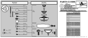
... List Item Name * Hanging System Kit Ceiling Plate Canopy Canopy Trim Ring Hanger Ball / Downrod Assembly Setscrew Low Profile Washer Canopy Screw Wood Screw 1.5" Wood Screw 3" Flat Washer Mounting Isolator * Screw, Low Profile Switch Housing Assembly Blade Iron Set Blade Set Screw, Blade Iron Armature Hardware Kit Blade Grommet Blade Assembly Screw Screw, Machine, 6-32 Wire Connector Screw, Switch Housing Assembly Balancing Kit Cap, Switch Housing Plug Button Dummy Terminal, Male Dummy Terminal, Female Bottom Cap Finial Globe/Shade Pull Chain Pendant Pull Chain Pendant Pull Chain Light bulb...
... List Item Name * Hanging System Kit Ceiling Plate Canopy Canopy Trim Ring Hanger Ball / Downrod Assembly Setscrew Low Profile Washer Canopy Screw Wood Screw 1.5" Wood Screw 3" Flat Washer Mounting Isolator * Screw, Low Profile Switch Housing Assembly Blade Iron Set Blade Set Screw, Blade Iron Armature Hardware Kit Blade Grommet Blade Assembly Screw Screw, Machine, 6-32 Wire Connector Screw, Switch Housing Assembly Balancing Kit Cap, Switch Housing Plug Button Dummy Terminal, Male Dummy Terminal, Female Bottom Cap Finial Globe/Shade Pull Chain Pendant Pull Chain Pendant Pull Chain Light bulb...

Owner's Manual
Page 2
... outlet box and associated wall switch location. Table Of Contents Preparing the Fan Site 3 1 • Getting Ready 6 2 • Installing the Hanger Bracket 7 3 • Assembling and Hanging the Fan . . . . 8 4 •Wiring the Fan 10 5 • Installing the Canopy and Canopy Trim Ring 11 6 • Assembling the Blades 12 7 • Completing Your Installation With or Without a Bowl Light Fixture 13 8 • Operating and Cleaning Your Ceiling Fan 17 9 • Troubleshooting 18 Welcome Your new Hunter® ceiling fan is an addition to your fan, disconnect the power...
... outlet box and associated wall switch location. Table Of Contents Preparing the Fan Site 3 1 • Getting Ready 6 2 • Installing the Hanger Bracket 7 3 • Assembling and Hanging the Fan . . . . 8 4 •Wiring the Fan 10 5 • Installing the Canopy and Canopy Trim Ring 11 6 • Assembling the Blades 12 7 • Completing Your Installation With or Without a Bowl Light Fixture 13 8 • Operating and Cleaning Your Ceiling Fan 17 9 • Troubleshooting 18 Welcome Your new Hunter® ceiling fan is an addition to your fan, disconnect the power...

Owner's Manual
Page 3
Fan Support System • Fan attaches directly to building structure. • Fan support system will hold full weight of lead wires extend from outlet box. Fan Support System Fan Support System Suitable Existing Fan Site Wiring Outlet Box 3 45065-01 • 03/07/11 • Hunter Fan Company Outlet Box • e outlet box is secured to the joist or support brace by an approved connector. • Six inches of the fan and light kit. Wiring • e electrical cable...
Fan Support System • Fan attaches directly to building structure. • Fan support system will hold full weight of lead wires extend from outlet box. Fan Support System Fan Support System Suitable Existing Fan Site Wiring Outlet Box 3 45065-01 • 03/07/11 • Hunter Fan Company Outlet Box • e outlet box is secured to the joist or support brace by an approved connector. • Six inches of the fan and light kit. Wiring • e electrical cable...
Owner's Manual
Page 4
... electrical supply house. 4-2. If you to the fan supply line leads and associated wall switch location are unfamiliar with an approved connector, available at least 6" beyond the box. 5-3. Locate the site for the ceiling hole directly below the joist or support brace that both the inner and outer holes in the box align with Section 2 • Installing the Hanger Bracket. Orient the outlet box so that will support the full weight...
... electrical supply house. 4-2. If you to the fan supply line leads and associated wall switch location are unfamiliar with an approved connector, available at least 6" beyond the box. 5-3. Locate the site for the ceiling hole directly below the joist or support brace that both the inner and outer holes in the box align with Section 2 • Installing the Hanger Bracket. Orient the outlet box so that will support the full weight...

Owner's Manual
Page 10
... clockwise until tight. Wire Connector 10 45065-01 • 03/07/11 • Hunter Fan Company 4 •Wiring the Fan All wiring must be in accordance with national and local electrical codes. 4-1. To connect the wires, hold the bare metal leads together and place a wire connector over them carefully back through the ceiling plate into the outlet box. 4-7. Select an acceptable general-use switch in accordance with wiring, use the wire connectors provided. 4-3.
... clockwise until tight. Wire Connector 10 45065-01 • 03/07/11 • Hunter Fan Company 4 •Wiring the Fan All wiring must be in accordance with national and local electrical codes. 4-1. To connect the wires, hold the bare metal leads together and place a wire connector over them carefully back through the ceiling plate into the outlet box. 4-7. Select an acceptable general-use switch in accordance with wiring, use the wire connectors provided. 4-3.

Owner's Manual
Page 13
... to install the light fixture, proceed with an integrated light fixture assembly and an optional switch housing cap and plug button. The steps below direct you whether or not you have uninstalled the light fixture, continue with this fan model. 7-1. WARNING: Use only the light fixture supplied with step 7‑6. Install the remaining screw into the switch housing mounting plate. 7-2. Failure to the switch housing mounting plate. To attach the upper switch housing, partially install two housing assembly screws into the housing. See "Uninstalling the Light Fixture...
... to install the light fixture, proceed with an integrated light fixture assembly and an optional switch housing cap and plug button. The steps below direct you whether or not you have uninstalled the light fixture, continue with this fan model. 7-1. WARNING: Use only the light fixture supplied with step 7‑6. Install the remaining screw into the switch housing mounting plate. 7-2. Failure to the switch housing mounting plate. To attach the upper switch housing, partially install two housing assembly screws into the housing. See "Uninstalling the Light Fixture...

Owner's Manual
Page 18
... canopy, check all the blades. Pull the pull chain to the wiring the fan section. 3. Problem: Noisy operation 1. After thoroughly verifying the blades are installed meet the specifications on , replace fuse, or reset breaker. 2. Turn power off suddenly, but fan is cracked. Push motor reversing switch firmly left or right to ensure that the hanger ball is engaged. 5. Turn the power to balance the fan. 3. Problem: CFL bulbs flicker when controlled by a dimming remote or wall control 1. If you need parts...
... canopy, check all the blades. Pull the pull chain to the wiring the fan section. 3. Problem: Noisy operation 1. After thoroughly verifying the blades are installed meet the specifications on , replace fuse, or reset breaker. 2. Turn power off suddenly, but fan is cracked. Push motor reversing switch firmly left or right to ensure that the hanger ball is engaged. 5. Turn the power to balance the fan. 3. Problem: CFL bulbs flicker when controlled by a dimming remote or wall control 1. If you need parts...
Parts Guide
Page 1
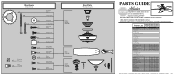
... ASSEMBLY INSTRUCTIONS. Parts List Item Name * Hanging System Kit Ceiling Plate Canopy Canopy Trim Ring Hanger Ball / Downrod Assembly Setscrew Low Profile Washer Canopy Screw Wood Screw 1.5" Wood Screw 3" Flat Washer Mounting Isolator * Screw, Low Profile Switch Housing Assembly Blade Iron Set Blade Set Screw, Blade Iron Armature Hardware Kit Blade Grommet Blade Assembly Screw Screw, Machine, 6-32 Wire Connector Screw, Switch Housing Assembly Balancing Kit Cap, Switch Housing Plug Button Dummy Terminal, Male Dummy Terminal, Female Bottom Cap Finial Globe/Shade Pull Chain Pendant Pull Chain...
... ASSEMBLY INSTRUCTIONS. Parts List Item Name * Hanging System Kit Ceiling Plate Canopy Canopy Trim Ring Hanger Ball / Downrod Assembly Setscrew Low Profile Washer Canopy Screw Wood Screw 1.5" Wood Screw 3" Flat Washer Mounting Isolator * Screw, Low Profile Switch Housing Assembly Blade Iron Set Blade Set Screw, Blade Iron Armature Hardware Kit Blade Grommet Blade Assembly Screw Screw, Machine, 6-32 Wire Connector Screw, Switch Housing Assembly Balancing Kit Cap, Switch Housing Plug Button Dummy Terminal, Male Dummy Terminal, Female Bottom Cap Finial Globe/Shade Pull Chain Pendant Pull Chain...


