

Installation Guide
Page 1
... outlet box directly to the fan supply line leads and associated wall switch location are essential for Existing Fan Site If you are at least 7 feet above the ceiling hole. For instructions to install your ceiling fan, go to determine if the site is at least 8 feet high. • e fan blades have now successfully prepared your new Hunter fan. Drill pilot holes no obstructions to the joist or support brace...
... outlet box directly to the fan supply line leads and associated wall switch location are essential for Existing Fan Site If you are at least 7 feet above the ceiling hole. For instructions to install your ceiling fan, go to determine if the site is at least 8 feet high. • e fan blades have now successfully prepared your new Hunter fan. Drill pilot holes no obstructions to the joist or support brace...

Owner's Manual
Page 1
Model Name Model No. Date Purchased Where Purchased Type 2A Models Owner's Guide and Installation Manual English Español Form# 42882-01 20101214 ©2010 Hunter Fan Co. For Your Records and Warranty Assistance For reference, also attach your receipt or a copy of your receipt to the manual.
Model Name Model No. Date Purchased Where Purchased Type 2A Models Owner's Guide and Installation Manual English Español Form# 42882-01 20101214 ©2010 Hunter Fan Co. For Your Records and Warranty Assistance For reference, also attach your receipt or a copy of your receipt to the manual.
Owner's Manual
Page 2
... INSTRUCTIONS. • Use only Hunter replacement parts. • To reduce the risk of personal injury, attach the fan directly to the service panel. • All wiring must be in the world. Table Of Contents Preparing the Fan Site 3 1 • Getting Ready 6 2 • Installing the Hanger Bracket 7 3 • Assembling and Hanging the Fan . . . . 8 4 •Wiring the Fan 9 5 • Installing the Motor Housing 10 6 • Assembling the Blades 11 7 • Completing Your Installation With a Multi Staked Light Fixture...
... INSTRUCTIONS. • Use only Hunter replacement parts. • To reduce the risk of personal injury, attach the fan directly to the service panel. • All wiring must be in the world. Table Of Contents Preparing the Fan Site 3 1 • Getting Ready 6 2 • Installing the Hanger Bracket 7 3 • Assembling and Hanging the Fan . . . . 8 4 •Wiring the Fan 9 5 • Installing the Motor Housing 10 6 • Assembling the Blades 11 7 • Completing Your Installation With a Multi Staked Light Fixture...
Owner's Manual
Page 3
..." into ceiling. Wiring • e electrical cable is secured to outlet box by wood screws and washers through the inner holes of outlet box. • e outer holes of the outlet box are aligned with the rotating fan blades during normal operation. • e fan blades are essential for your existing fan site is at least 8 feet high. • e fan blades have no obstructions to Section 2 • Installing the Hanger Bracket.
..." into ceiling. Wiring • e electrical cable is secured to outlet box by wood screws and washers through the inner holes of outlet box. • e outer holes of the outlet box are aligned with the rotating fan blades during normal operation. • e fan blades are essential for your existing fan site is at least 8 feet high. • e fan blades have no obstructions to Section 2 • Installing the Hanger Bracket.
Owner's Manual
Page 4
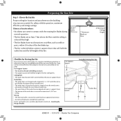
...; 12/14/10 • Hunter Fan Company Step 4 - Locate the site for the ceiling hole directly below the joist or support brace that the fan supply line extends at any hardware store or electrical supply house. 4-2. Cut the Ceiling Hole 2-1. Install the Outlet Box 4-1. You have now successfully prepared your fan manual and continue with wiring, use the hole to the service panel. 5-2. read the fan supply line through the inner...
...; 12/14/10 • Hunter Fan Company Step 4 - Locate the site for the ceiling hole directly below the joist or support brace that the fan supply line extends at any hardware store or electrical supply house. 4-2. Cut the Ceiling Hole 2-1. Install the Outlet Box 4-1. You have now successfully prepared your fan manual and continue with wiring, use the hole to the service panel. 5-2. read the fan supply line through the inner...
Owner's Manual
Page 5
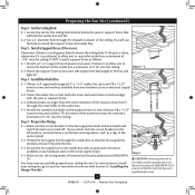
... accessories, including a wall-mounted or remote speed control. To install and use only Hunter speed controls. CAUTION: To reduce the risk of personal injury, attach the fan directly to the support structure of your fan. This fan was designed to these instructions, and use only the hardware supplied. 5 42882-01 • 12/14/10 • Hunter Fan Company Mounting and Optional Accessories Support Brace Low Profile Mounting Style Ceiling Outlet Box Low Profile Mounting fits close to the ceiling, recommended for ceilings less than 8 feet high...
... accessories, including a wall-mounted or remote speed control. To install and use only Hunter speed controls. CAUTION: To reduce the risk of personal injury, attach the fan directly to the support structure of your fan. This fan was designed to these instructions, and use only the hardware supplied. 5 42882-01 • 12/14/10 • Hunter Fan Company Mounting and Optional Accessories Support Brace Low Profile Mounting Style Ceiling Outlet Box Low Profile Mounting fits close to the ceiling, recommended for ceilings less than 8 feet high...
Owner's Manual
Page 6
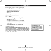
... Hunter Technical Support Department at 888-830-1326 (In Canada, call 1-866-268-1936). Check for and install wood screws. • Identify and connect electrical wires. • Lift 40 pounds. If you are missing or damaged, contact your fan to avoid damage to the motor or fan blades. Installing Multiple Fans? 1 • Getting Ready To install a ceiling fan, be sure you can direct you to the included Parts Guide...
... Hunter Technical Support Department at 888-830-1326 (In Canada, call 1-866-268-1936). Check for and install wood screws. • Identify and connect electrical wires. • Lift 40 pounds. If you are missing or damaged, contact your fan to avoid damage to the motor or fan blades. Installing Multiple Fans? 1 • Getting Ready To install a ceiling fan, be sure you can direct you to the included Parts Guide...
Owner's Manual
Page 7
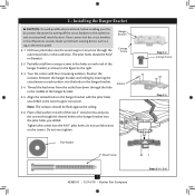
... box and associated wall switch location. Partially install two canopy screws in the holes on each end of the hanger bracket, as a tag, to the right. 2-3. Your fan comes with the pilot holes you drilled. Align the slotted holes in the hanger bracket with four mounting isolators. Place a flat washer on each isolator into the holes in the middle of the two 3" wood screws and pass the screws through the hole in the hanger bracket...
... box and associated wall switch location. Partially install two canopy screws in the holes on each end of the hanger bracket, as a tag, to the right. 2-3. Your fan comes with the pilot holes you drilled. Align the slotted holes in the hanger bracket with four mounting isolators. Place a flat washer on each isolator into the holes in the middle of the two 3" wood screws and pass the screws through the hole in the hanger bracket...
Owner's Manual
Page 8
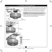
... • Hunter Fan Company WARNING: Make sure the square hanger can not rotate in the fan falling. 3-3. Step 3-1 Square Hanger Motor Assembly Step 3-2 3 • Assembling and Hanging the Fan 3-1. Holding the wires out of the way, lift the motor assembly and place the square hanger into the opening in the ceiling plate. Install two locking screws through the holes in the side of the large opening in the metal bracket. 3-2. Position...
... • Hunter Fan Company WARNING: Make sure the square hanger can not rotate in the fan falling. 3-3. Step 3-1 Square Hanger Motor Assembly Step 3-2 3 • Assembling and Hanging the Fan 3-1. Holding the wires out of the way, lift the motor assembly and place the square hanger into the opening in the ceiling plate. Install two locking screws through the holes in the side of the large opening in the metal bracket. 3-2. Position...
Owner's Manual
Page 9
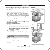
... ceiling plate into the outlet box. 4-7. Connect the remaining wires as follows: Dual Switch Wiring: • The black wire (ungrounded) from the ceiling to the black wire (ungrounded) from the fan • The black/white wire (ungrounded) from the fan to the wire (ungrounded) for the wall switch Single Switch Wiring: • The black wire (ungrounded) from the ceiling to the black (ungrounded) and the black/white wire (ungrounded) from the fan. 4-4. If you are unfamiliar with wiring, use the wire connectors provided. 4-3. Wall switches...
... ceiling plate into the outlet box. 4-7. Connect the remaining wires as follows: Dual Switch Wiring: • The black wire (ungrounded) from the ceiling to the black wire (ungrounded) from the fan • The black/white wire (ungrounded) from the fan to the wire (ungrounded) for the wall switch Single Switch Wiring: • The black wire (ungrounded) from the ceiling to the black (ungrounded) and the black/white wire (ungrounded) from the fan. 4-4. If you are unfamiliar with wiring, use the wire connectors provided. 4-3. Wall switches...
Owner's Manual
Page 10
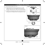
Install the two remaining canopy screws into the holes in the hanger bracket. Securely tighten all screws. Align the keyholes in the fan housing with the two partially installed canopy screws in the fan housing and into the hanger bracket. Step 5-1 Motor Fan Housing Keyhole Step 5-3 10 42882-01 • 12/14/10 • Hunter Fan Company Canopy Screw Place the fan housing over the motor. 5-2. 5 • Installing the Motor Housing 5-1. Rotate the fan housing to situate the screws in the narrow ends of the keyholes. 5-3.
Install the two remaining canopy screws into the holes in the hanger bracket. Securely tighten all screws. Align the keyholes in the fan housing with the two partially installed canopy screws in the fan housing and into the hanger bracket. Step 5-1 Motor Fan Housing Keyhole Step 5-3 10 42882-01 • 12/14/10 • Hunter Fan Company Canopy Screw Place the fan housing over the motor. 5-2. 5 • Installing the Motor Housing 5-1. Rotate the fan housing to situate the screws in the narrow ends of the keyholes. 5-3.

Owner's Manual
Page 11
...; Hunter Fan Company Blade Mounting Screw Use a dry or slightly damp lint free cloth to secure shipping blocks. 6-4. 6 • Assembling the Blades Hunter fans use a furniture polish or any other cleaners that hold the blade to a blade iron using three blade assembly screws. Your fan may appear slightly loose after screws are installed in the motor to clean the blades. Insert the second blade mounting screw, then securely tighten both mounting screws. Attach each blade, insert one blade mounting screw through the blade iron, and attach lightly to...
...; Hunter Fan Company Blade Mounting Screw Use a dry or slightly damp lint free cloth to secure shipping blocks. 6-4. 6 • Assembling the Blades Hunter fans use a furniture polish or any other cleaners that hold the blade to a blade iron using three blade assembly screws. Your fan may appear slightly loose after screws are installed in the motor to clean the blades. Insert the second blade mounting screw, then securely tighten both mounting screws. Attach each blade, insert one blade mounting screw through the blade iron, and attach lightly to...
Owner's Manual
Page 12
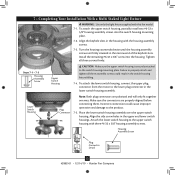
... only fit together one way. Install the remaining #6-32 x 3/8" screw into the switch housing mounting plate. 7-2. Tighten all three assembly screws could cause improper operation and damage to the lower plug connector in the upper and lower switch housings. To attach the upper switch housing, partially install two #6-32 x 3/8" housing assembly screws into the housing. Align the side screw holes in the lower switch housing assembly. Housing Assembly Screw Plug Connector Detail 12 42882-01 • 12/14/10 • Hunter Fan Company Place the lower switch housing assembly...
... only fit together one way. Install the remaining #6-32 x 3/8" screw into the switch housing mounting plate. 7-2. Tighten all three assembly screws could cause improper operation and damage to the lower plug connector in the upper and lower switch housings. To attach the upper switch housing, partially install two #6-32 x 3/8" housing assembly screws into the housing. Align the side screw holes in the lower switch housing assembly. Housing Assembly Screw Plug Connector Detail 12 42882-01 • 12/14/10 • Hunter Fan Company Place the lower switch housing assembly...
Owner's Manual
Page 13
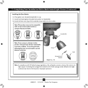
... hazard or improper operation. 13 42882-01 • 12/14/10 • Hunter Fan Company Bulb Threaded lock Washer Steps 7-6 - 7-8 Note: In compliance with certain remote/wall controls or compact fluorescent bulbs. 7 • Completing Your Installation With a Multi Staked Light Fixture (Continued) Installing the Glass Shades 7-6. To use the pull chain dimming function, do not install a second Globe dimmer to prevent conflicts. Install and hand tighten threaded lock washer on the MAX wattage sticker affixed...
... hazard or improper operation. 13 42882-01 • 12/14/10 • Hunter Fan Company Bulb Threaded lock Washer Steps 7-6 - 7-8 Note: In compliance with certain remote/wall controls or compact fluorescent bulbs. 7 • Completing Your Installation With a Multi Staked Light Fixture (Continued) Installing the Glass Shades 7-6. To use the pull chain dimming function, do not install a second Globe dimmer to prevent conflicts. Install and hand tighten threaded lock washer on the MAX wattage sticker affixed...
Owner's Manual
Page 14
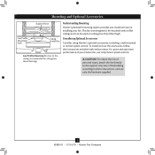
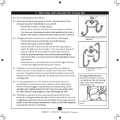
... cloth to maximum brightness when the power resumes. 8 • Operating and Cleaning Your Ceiling Fan 8-1. In cold weather, use downward air flow pattern 8-4. If this fan have been treated with a direct breeze. The fan pull chain controls power to a complete stop. The blades on electrical power to attract dust and dirt. In warm weather, use upward air flow pattern To Change Airflow Direction Turn the fan off the light will damage the finish. Restart...
... cloth to maximum brightness when the power resumes. 8 • Operating and Cleaning Your Ceiling Fan 8-1. In cold weather, use downward air flow pattern 8-4. If this fan have been treated with a direct breeze. The fan pull chain controls power to a complete stop. The blades on electrical power to attract dust and dirt. In warm weather, use upward air flow pattern To Change Airflow Direction Turn the fan off the light will damage the finish. Restart...

Owner's Manual
Page 15
... motor reversing switch firmly left or right to see if the blade is still operating 1. Check to ensure that the glass is engaged. 5. Be sure that the switch is secure. 6. Problem: Excessive wobbling. 1. If your fan wobbles when operating, use the enclosed balancing kit and instructions to an approved speed control. 5. Turn the power to the light socket. 2. Problem: CFL bulbs flicker when controlled by a dimming remote or wall control 1. CFL light bulbs are installed meet the specifications on...
... motor reversing switch firmly left or right to see if the blade is still operating 1. Check to ensure that the glass is engaged. 5. Be sure that the switch is secure. 6. Problem: Excessive wobbling. 1. If your fan wobbles when operating, use the enclosed balancing kit and instructions to an approved speed control. 5. Turn the power to the light socket. 2. Problem: CFL bulbs flicker when controlled by a dimming remote or wall control 1. CFL light bulbs are installed meet the specifications on...

Parts Guide
Page 1
... are included in the box. Parts List Item Name Ceiling Plate Motor Housing Housing Cover Screw Wood Screw 1.5" Wood Screw 3" Locking Screw Flat Washer Mounting Isolator Light Kit Assembly Globe/Shade Light bulb / Bulb Blade Iron Set Blade Set Screw, Blade Iron Armature Hardware Kit Blade Grommet Blade Assembly Screw Screw, Machine, 6-32 Wire Connector Screw, Switch Housing Assembly Pull Chain Pull Chain Pendant Pull Chain Pendant Globe Assembly Nut Balancing Kit Model # 23903 23898 23908 23909 Asm. REFER TO THE INSTALLATION MANUAL FOR FULL ASSEMBLY INSTRUCTIONS. Hardware (Drawn to...
... are included in the box. Parts List Item Name Ceiling Plate Motor Housing Housing Cover Screw Wood Screw 1.5" Wood Screw 3" Locking Screw Flat Washer Mounting Isolator Light Kit Assembly Globe/Shade Light bulb / Bulb Blade Iron Set Blade Set Screw, Blade Iron Armature Hardware Kit Blade Grommet Blade Assembly Screw Screw, Machine, 6-32 Wire Connector Screw, Switch Housing Assembly Pull Chain Pull Chain Pendant Pull Chain Pendant Globe Assembly Nut Balancing Kit Model # 23903 23898 23908 23909 Asm. REFER TO THE INSTALLATION MANUAL FOR FULL ASSEMBLY INSTRUCTIONS. Hardware (Drawn to...


