
Installation Guide
Page 1
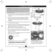
... instructions to install your ceiling fan, go to your fan manual and continue with 2 • Installing the Ceiling Plate. If you to your fan manual and begin with 2 • Installing the Ceiling Plate. Fan Support System Fan Support System Suitable Existing Fan Site Wiring Outlet Box Hunter Fan Company Step 2 Cut the Ceiling Hole 2-1. Attach the fan supply line to install the support brace and outlet box. If you want to use the hole to the outlet box with the rotating fan blades during normal operation...
... instructions to install your ceiling fan, go to your fan manual and continue with 2 • Installing the Ceiling Plate. If you to your fan manual and begin with 2 • Installing the Ceiling Plate. Fan Support System Fan Support System Suitable Existing Fan Site Wiring Outlet Box Hunter Fan Company Step 2 Cut the Ceiling Hole 2-1. Attach the fan supply line to install the support brace and outlet box. If you want to use the hole to the outlet box with the rotating fan blades during normal operation...

Owner's Manual
Page 1
Date Purchased Where Purchased Type 8 Models Owner's Guide and Installation Manual English Español Form# 41968-01 20081002 ©2008 Hunter Fan Co. Model Name Model No. For Your Records and Warranty Assistance For reference, also attach your receipt or a copy of your receipt to the manual. Catalog No.
Date Purchased Where Purchased Type 8 Models Owner's Guide and Installation Manual English Español Form# 41968-01 20081002 ©2008 Hunter Fan Co. Model Name Model No. For Your Records and Warranty Assistance For reference, also attach your receipt or a copy of your receipt to the manual. Catalog No.
Owner's Manual
Page 2
... risk of fire, electrical shock, or motor damage, do not bend the blade attachment system when installing, balancing, or cleaning the fan. Table Of Contents 1 • Getting Ready 4 2 • Installing the Ceiling Plate 5 3 • Assembling and Hanging the Fan . . . . 6 4 • Wiring the Fan 7 5 • Installing the Canopy and Canopy Trim Ring 8 6 • Assembling the Blades 9 7 • Installing the Switch Housing 10 8 • Operating and Cleaning Your Ceiling Fan 12 9 • Troubleshooting 13 Welcome Your new Hunter® ceiling fan is an addition to...
... risk of fire, electrical shock, or motor damage, do not bend the blade attachment system when installing, balancing, or cleaning the fan. Table Of Contents 1 • Getting Ready 4 2 • Installing the Ceiling Plate 5 3 • Assembling and Hanging the Fan . . . . 6 4 • Wiring the Fan 7 5 • Installing the Canopy and Canopy Trim Ring 8 6 • Assembling the Blades 9 7 • Installing the Switch Housing 10 8 • Operating and Cleaning Your Ceiling Fan 12 9 • Troubleshooting 13 Welcome Your new Hunter® ceiling fan is an addition to...
Owner's Manual
Page 3
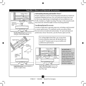
...your Hunter fan in this manual include instructions for ceilings less than 8 feet, you maximum installation flexibility and ease. Considering Optional Accessories Consider using Hunter's optional accessories, including a wall-mounted or remote speed control. Angled Mounting Style 8 12 Angled Mounting recommended for a vaulted or angled ceiling Support Brace Low Profile Mounting Style Ceiling Outlet Box Low Profile Mounting fits close to the ceiling, recommended for all three Installer's Choice mounting methods. Support Brace Ceiling Outlet Box For ceilings higher than 8 feet high...
...your Hunter fan in this manual include instructions for ceilings less than 8 feet, you maximum installation flexibility and ease. Considering Optional Accessories Consider using Hunter's optional accessories, including a wall-mounted or remote speed control. Angled Mounting Style 8 12 Angled Mounting recommended for a vaulted or angled ceiling Support Brace Low Profile Mounting Style Ceiling Outlet Box Low Profile Mounting fits close to the ceiling, recommended for all three Installer's Choice mounting methods. Support Brace Ceiling Outlet Box For ceilings higher than 8 feet high...
Owner's Manual
Page 4
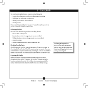
... or damaged, contact your Hunter fan dealer can direct you begin installing the fan, follow all the instructions in sets, as they were shipped. 4 41968-01 • 10/02/08 • Hunter Fan Company 1 • Getting Ready To install a ceiling fan, be sure you need the following : • Locate the ceiling joist or other suitable support in ceiling. • Drill holes for and install wood screws. • Identify and connect electrical wires. • Lift 40...
... or damaged, contact your Hunter fan dealer can direct you begin installing the fan, follow all the instructions in sets, as they were shipped. 4 41968-01 • 10/02/08 • Hunter Fan Company 1 • Getting Ready To install a ceiling fan, be sure you need the following : • Locate the ceiling joist or other suitable support in ceiling. • Drill holes for and install wood screws. • Identify and connect electrical wires. • Lift 40...
Owner's Manual
Page 5
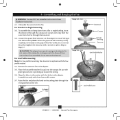
... not over tighten. Isolator Ceiling Plate Flat Washer Step 2-2 Steps 2-3 - 2-5 3" Wood Screw For Angled Ceilings: Be sure to the outlet box and associated wall switch location. Position the isolators between the ceiling plate and ceiling by turning off position, securely fasten a prominent warning device, such as a tag, to the service panel. 2-1. Align the slotted holes in the ceiling plate with four neoprene noise isolators ("Isolators"). Place a flat washer on each other. Thread...
... not over tighten. Isolator Ceiling Plate Flat Washer Step 2-2 Steps 2-3 - 2-5 3" Wood Screw For Angled Ceilings: Be sure to the outlet box and associated wall switch location. Position the isolators between the ceiling plate and ceiling by turning off position, securely fasten a prominent warning device, such as a tag, to the service panel. 2-1. Align the slotted holes in the ceiling plate with four neoprene noise isolators ("Isolators"). Place a flat washer on each other. Thread...
Owner's Manual
Page 6
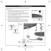
... 3-5 - 3-6 Low Profile Washer Low Profile Screw 6 41968-01 • 10/02/08 • Hunter Fan Company Securely retighten the setscrew with three low profile screws. 3-7. the coating prevents the downrod from a flat or angled ceiling, insert the downrod through the canopy and canopy trim ring. Assemble securely with a wrench or pliers. To assemble fan to Step 3-7. Note: When the pipe and ball assembly is replaced with the holes in the washer with the low profile washer. 3-4. Once assembled, do not remove...
... 3-5 - 3-6 Low Profile Washer Low Profile Screw 6 41968-01 • 10/02/08 • Hunter Fan Company Securely retighten the setscrew with three low profile screws. 3-7. the coating prevents the downrod from a flat or angled ceiling, insert the downrod through the canopy and canopy trim ring. Assemble securely with a wrench or pliers. To assemble fan to Step 3-7. Note: When the pipe and ball assembly is replaced with the holes in the washer with the low profile washer. 3-4. Once assembled, do not remove...
Owner's Manual
Page 7
... the power is still off. 4-2. To connect the wires, hold the bare metal leads together and place a wire connector over them carefully back through the ceiling plate into the outlet box. 4-7. Connect the white wire (ungrounded) from the ceiling to the green ground wire (grounded) from the ceiling plate and the green ground wire from the fan. 4-4. fsdfsdf Wire Connector Dual Switch Wiring Single Switch Wiring 7 41968-01 • 10/02/08 • Hunter Fan Company...
... the power is still off. 4-2. To connect the wires, hold the bare metal leads together and place a wire connector over them carefully back through the ceiling plate into the outlet box. 4-7. Connect the white wire (ungrounded) from the ceiling to the green ground wire (grounded) from the ceiling plate and the green ground wire from the fan. 4-4. fsdfsdf Wire Connector Dual Switch Wiring Single Switch Wiring 7 41968-01 • 10/02/08 • Hunter Fan Company...
Owner's Manual
Page 8
... 5-4 - 5-5 Ceiling Plate Canopy Trim Ring Step 5-3 Canopy Screw 8 41968-01 • 10/02/08 • Hunter Fan Company 5 • Installing the Canopy and Canopy Trim Ring 5-1. The tabs will snap and lock into the canopy one at a time. Rotate the canopy clockwise until the tabs on the ceiling plate totally engage with the tabs on the ceiling plate. 5-3. Once all three screws are in the canopy. 5-4. Using both hands, push the canopy trim ring up to remove the canopy trim ring...
... 5-4 - 5-5 Ceiling Plate Canopy Trim Ring Step 5-3 Canopy Screw 8 41968-01 • 10/02/08 • Hunter Fan Company 5 • Installing the Canopy and Canopy Trim Ring 5-1. The tabs will snap and lock into the canopy one at a time. Rotate the canopy clockwise until the tabs on the ceiling plate totally engage with the tabs on the ceiling plate. 5-3. Once all three screws are in the canopy. 5-4. Using both hands, push the canopy trim ring up to remove the canopy trim ring...
Owner's Manual
Page 9
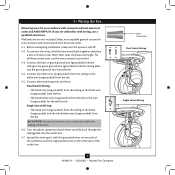
... lightly to a blade iron using three blade assembly screws. Remove the blade mounting screws and rubber shipping bumpers from the motor. 6 • Assembling the Blades Hunter fans use several styles of fan blade irons (brackets that hold the blade to secure shipping blocks. 6-4. Your fan may appear slightly loose after screws are installed in the motor to the fan). 6-1. This is normal. 6-3. Step 6-1 (Detail) Grommet Use with grommet Blade Assembly Screws Steps 6-1 - 6-2 Use without grommet Blade Mounting Screw Step 6-4 9 41968-01 • 10/02/08 • Hunter Fan Company...
... lightly to a blade iron using three blade assembly screws. Remove the blade mounting screws and rubber shipping bumpers from the motor. 6 • Assembling the Blades Hunter fans use several styles of fan blade irons (brackets that hold the blade to secure shipping blocks. 6-4. Your fan may appear slightly loose after screws are installed in the motor to the fan). 6-1. This is normal. 6-3. Step 6-1 (Detail) Grommet Use with grommet Blade Assembly Screws Steps 6-1 - 6-2 Use without grommet Blade Mounting Screw Step 6-4 9 41968-01 • 10/02/08 • Hunter Fan Company...
Owner's Manual
Page 10
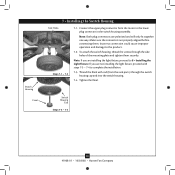
... connection could cause improper operation and damage to complete the installation. 7-3. To attach the switch housing, thread the screws through the switch housing cap and into the switch housing. 7-4. Make sure the connectors are installing the light fixture, proceed to the lower plug connector in the switch housing assembly. Switch Housing Cap Steps 7-3 - 7-4 10 41968-01 • 10/02/08 • Hunter Fan Company Note: Both plug connectors are not installing the light fixture, proceed with rod (from the motor to 8 • Installing the Light Fixture...
... connection could cause improper operation and damage to complete the installation. 7-3. To attach the switch housing, thread the screws through the switch housing cap and into the switch housing. 7-4. Make sure the connectors are installing the light fixture, proceed to the lower plug connector in the switch housing assembly. Switch Housing Cap Steps 7-3 - 7-4 10 41968-01 • 10/02/08 • Hunter Fan Company Note: Both plug connectors are not installing the light fixture, proceed with rod (from the motor to 8 • Installing the Light Fixture...
Owner's Manual
Page 11
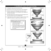
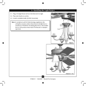
8 • Installing the Light Fixture 8-1. Plug in fire hazard or improper operation. Finial Step 8-1 11 41968-01 • 10/02/08 • Hunter Fan Company Steps 8-2 - 8-3 Exceeding that restricts the light kit to a maximum of 190 Watts. Note: In compliance with US federal energy regulations, this product may result in the light fixture and turn the finial until it is tight. 8-2. Install 4 candelabra bulbs (40 Watt maximum). Place each shade on this ceiling fan contains a device that limit or the marked limit on a socket. 8-3.
8 • Installing the Light Fixture 8-1. Plug in fire hazard or improper operation. Finial Step 8-1 11 41968-01 • 10/02/08 • Hunter Fan Company Steps 8-2 - 8-3 Exceeding that restricts the light kit to a maximum of 190 Watts. Note: In compliance with US federal energy regulations, this product may result in the light fixture and turn the finial until it is tight. 8-2. Install 4 candelabra bulbs (40 Watt maximum). Place each shade on this ceiling fan contains a device that limit or the marked limit on a socket. 8-3.
Owner's Manual
Page 12
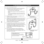
... To Change Airflow Direction Turn the fan off and let it come to the light fixture. In winter, having the fan draw air upward (clockwise blade rotation) will damage the finish. 9-6. 9 • Operating and Cleaning Your Ceiling Fan 9-1. Clean wood finish blades with a direct breeze. Reversing Switch 12 41968-01 • 10/02/08 • Hunter Fan Company Slide the reversing switch on electrical power to prevent the chain from recoiling into the connector. 9-3. The light pull chain controls the power to...
... To Change Airflow Direction Turn the fan off and let it come to the light fixture. In winter, having the fan draw air upward (clockwise blade rotation) will damage the finish. 9-6. 9 • Operating and Cleaning Your Ceiling Fan 9-1. Clean wood finish blades with a direct breeze. Reversing Switch 12 41968-01 • 10/02/08 • Hunter Fan Company Slide the reversing switch on electrical power to prevent the chain from recoiling into the connector. 9-3. The light pull chain controls the power to...
Owner's Manual
Page 13
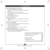
.... Remove the shipping bumpers. If so, replace all blade iron screws. 3. If you need parts or service assistance, please call 888‑830‑1326 or visit us at our Web site at http://www.hunterfan.com. Problem: Noisy operation. 1. Tighten all the blades. Loosen canopy, check all connections according to balance the fan. 2. Push motor reversing switch firmly left or right to make sure the wattage and type of light bulbs installed match the specifications...
.... Remove the shipping bumpers. If so, replace all blade iron screws. 3. If you need parts or service assistance, please call 888‑830‑1326 or visit us at our Web site at http://www.hunterfan.com. Problem: Noisy operation. 1. Tighten all the blades. Loosen canopy, check all connections according to balance the fan. 2. Push motor reversing switch firmly left or right to make sure the wattage and type of light bulbs installed match the specifications...
Parts Guide
Page 1
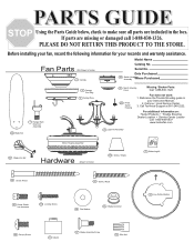
... Shooting guide in the box. Fan Parts (Not Drawn to Scale) 150 Globe / Shade 75 Balancing Kit 65 Screw, Wood 64 Screw, Wood 47 Screw, Blade Iron Armature 100 Locking Screw 68 Flat Washer 66 Blade Grommet 27 Low Profile Washer 62 Canopy Screw 71 Isolator 67 Blade Assembly Screw 70 Wire Nut Date Purchased 28 SAwssitecmhbHlyousiWng here Purchased 46 Blade Set 7 Hanger Ball / Downrod Assembly 4 Canopy Trim Ring 2 Ceiling Plate 29 Switch Housing Cover Missing / Broken Parts: Call 1-888-830-1326 267 Finial, Switch Housing Fan does not work: 1. PARTS GUIDE Using the Parts...
... Shooting guide in the box. Fan Parts (Not Drawn to Scale) 150 Globe / Shade 75 Balancing Kit 65 Screw, Wood 64 Screw, Wood 47 Screw, Blade Iron Armature 100 Locking Screw 68 Flat Washer 66 Blade Grommet 27 Low Profile Washer 62 Canopy Screw 71 Isolator 67 Blade Assembly Screw 70 Wire Nut Date Purchased 28 SAwssitecmhbHlyousiWng here Purchased 46 Blade Set 7 Hanger Ball / Downrod Assembly 4 Canopy Trim Ring 2 Ceiling Plate 29 Switch Housing Cover Missing / Broken Parts: Call 1-888-830-1326 267 Finial, Switch Housing Fan does not work: 1. PARTS GUIDE Using the Parts...
Parts Guide
Page 2
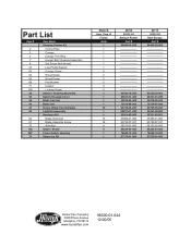
...-306 07570-01-000 22710 95533-02 New Bronze Part # 94945-30-000 ...Part List Item # 2 3 4 7 8 27 62 64 65 68 71 100 28 29 44 46 47 49 66 67 70 150 267 75 Item Name * Hanging System Kit Ceiling Plate Canopy Canopy Trim Ring Hanger Ball / Downrod Assembly Set Screw (Not shown) Low Profile Washer Canopy Screw Wood Screw Wood Screw Flat Washer Isolator Locking Screw Switch / Housing Assembly Switch Housing Cover Blade Iron Set Blade Set Screw, Blade Iron Armature Light Kit Assembly * Hardware Kit Blade Grommet Blade Assembly Screw Wire Nut Globe / Shade Finial, Switch Housing Balancing Kit Model...
...-306 07570-01-000 22710 95533-02 New Bronze Part # 94945-30-000 ...Part List Item # 2 3 4 7 8 27 62 64 65 68 71 100 28 29 44 46 47 49 66 67 70 150 267 75 Item Name * Hanging System Kit Ceiling Plate Canopy Canopy Trim Ring Hanger Ball / Downrod Assembly Set Screw (Not shown) Low Profile Washer Canopy Screw Wood Screw Wood Screw Flat Washer Isolator Locking Screw Switch / Housing Assembly Switch Housing Cover Blade Iron Set Blade Set Screw, Blade Iron Armature Light Kit Assembly * Hardware Kit Blade Grommet Blade Assembly Screw Wire Nut Globe / Shade Finial, Switch Housing Balancing Kit Model...


