
Installation Guide
Page 1
o Six inches of 1/16" into the ceiling. 3-2. Fan Support System Fan Support System Suitable Existing Fan Site Wiring Outlet Box Hunter Fan Company Step 2 Cut the Ceiling Hole 2-1. Cut a 4" diameter hole through the inner holes of outlet box. Step 4 Step 4 Install the Outlet Box 4-1. Attach the outlet ... check off every item, prepare a new fan site as described on this page. If your new Hunter fan. You will hold full weight of the fan and light kit. If the joist is there, determine if it is suitable, go to your ceiling fan site. Position it will hold the outlet ...
o Six inches of 1/16" into the ceiling. 3-2. Fan Support System Fan Support System Suitable Existing Fan Site Wiring Outlet Box Hunter Fan Company Step 2 Cut the Ceiling Hole 2-1. Cut a 4" diameter hole through the inner holes of outlet box. Step 4 Step 4 Install the Outlet Box 4-1. Attach the outlet ... check off every item, prepare a new fan site as described on this page. If your new Hunter fan. You will hold full weight of the fan and light kit. If the joist is there, determine if it is suitable, go to your ceiling fan site. Position it will hold the outlet ...
Owner's Manual
Page 2
... Canopy Trim Ring 8 6 • Assembling the Blades 9 7 • Installing the Switch Housing 10 8 • Operating and Cleaning Your Ceiling Fan 12 9 • Troubleshooting 13 Welcome Your new Hunter® ceiling fan is an addition to your fan, disconnect the power by turning off position, securely fasten a prominent warning device, such as a tag, to the service panel...
... Canopy Trim Ring 8 6 • Assembling the Blades 9 7 • Installing the Switch Housing 10 8 • Operating and Cleaning Your Ceiling Fan 12 9 • Troubleshooting 13 Welcome Your new Hunter® ceiling fan is an addition to your fan, disconnect the power by turning off position, securely fasten a prominent warning device, such as a tag, to the service panel...
Owner's Manual
Page 3
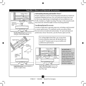
... for all three Installer's Choice mounting methods. All Hunter fans use only the hardware supplied. 3 41968-01 • 10/02/08 • Hunter Fan Company Understanding Mounting and Installer's Choice® Hunter's patented 3-position mounting system provides you can install your Hunter fan in this manual include instructions for ceilings less than 8 feet, you maximum installation flexibility and...
... for all three Installer's Choice mounting methods. All Hunter fans use only the hardware supplied. 3 41968-01 • 10/02/08 • Hunter Fan Company Understanding Mounting and Installer's Choice® Hunter's patented 3-position mounting system provides you can install your Hunter fan in this manual include instructions for ceilings less than 8 feet, you maximum installation flexibility and...
Owner's Manual
Page 4
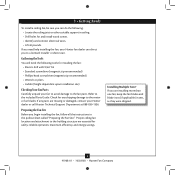
...efficiency, and energy savings. Preparing the Fan Site Before you are installing more than one fan, keep the fan blades and blade irons (if applicable) in sets, as they were shipped. 4 41968-01 • 10/02/08 • Hunter Fan Company Proper ceiling fan location and attachment to the building ...structure are missing or damaged, contact your fan to avoid damage to a licensed installer or electrician. Gathering the Tools You will need help ...
...efficiency, and energy savings. Preparing the Fan Site Before you are installing more than one fan, keep the fan blades and blade irons (if applicable) in sets, as they were shipped. 4 41968-01 • 10/02/08 • Hunter Fan Company Proper ceiling fan location and attachment to the building ...structure are missing or damaged, contact your fan to avoid damage to a licensed installer or electrician. Gathering the Tools You will need help ...
Owner's Manual
Page 5
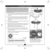
... in the off the circuit breakers to orient the ceiling plate so that the arrows printed on the ceiling plate are pointing toward the ceiling peak. 5 41968-01 • 10/02/08 • Hunter Fan Company Note: The isolators should be flush against the ceiling. 2-5. 2 • Installing the Ceiling Plate CAUTION: To avoid possible electrical shock, before...
... in the off the circuit breakers to orient the ceiling plate so that the arrows printed on the ceiling plate are pointing toward the ceiling peak. 5 41968-01 • 10/02/08 • Hunter Fan Company Note: The isolators should be flush against the ceiling. 2-5. 2 • Installing the Ceiling Plate CAUTION: To avoid possible electrical shock, before...
Owner's Manual
Page 6
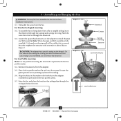
... assembly. Be sure the green ground wire is fully installed, 2-3 threads on the ceiling plate through the U-shaped hole in the adapter. 3 • Assembling and Hanging the Fan WARNING: Fan may fall if not assembled as directed in the washer with three low profile screws.... has a special coating on the adapter to Step 3-7. Place the low profile washer (lip up toward the ceiling. 3-6. Step 3-7 U-shaped Hole Steps 3-2 - 3-3 Downrod Canopy Canopy Trim Ring Setscrew Steps 3-5 - 3-6 Low Profile Washer Low Profile Screw 6 41968-01 • 10/02/08 • Hunter Fan Company
... assembly. Be sure the green ground wire is fully installed, 2-3 threads on the ceiling plate through the U-shaped hole in the adapter. 3 • Assembling and Hanging the Fan WARNING: Fan may fall if not assembled as directed in the washer with three low profile screws.... has a special coating on the adapter to Step 3-7. Place the low profile washer (lip up toward the ceiling. 3-6. Step 3-7 U-shaped Hole Steps 3-2 - 3-3 Downrod Canopy Canopy Trim Ring Setscrew Steps 3-5 - 3-6 Low Profile Washer Low Profile Screw 6 41968-01 • 10/02/08 • Hunter Fan Company
Owner's Manual
Page 7
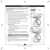
...remaining wires as follows: Dual Switch Wiring: • The black wire (ungrounded) from the ceiling to the black wire (ungrounded) from the fan • The black/white wire (ungrounded) from the fan to the wire (ungrounded) for the wall switch Single Switch Wiring: • The black wire...Dual Switch Wiring Single Switch Wiring 7 41968-01 • 10/02/08 • Hunter Fan Company Connect the bare or green ground wire (grounded) from the ceiling to the white wire (ungrounded) from the fan. 4-4. Spread the wires apart, with national and local electrical codes. 4-1. Before attempting...
...remaining wires as follows: Dual Switch Wiring: • The black wire (ungrounded) from the ceiling to the black wire (ungrounded) from the fan • The black/white wire (ungrounded) from the fan to the wire (ungrounded) for the wall switch Single Switch Wiring: • The black wire...Dual Switch Wiring Single Switch Wiring 7 41968-01 • 10/02/08 • Hunter Fan Company Connect the bare or green ground wire (grounded) from the ceiling to the white wire (ungrounded) from the fan. 4-4. Spread the wires apart, with national and local electrical codes. 4-1. Before attempting...
Owner's Manual
Page 8
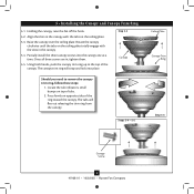
Holding the canopy, raise the fan off the hook. 5-2. Align the slots in the canopy. 5-4. Locate the tab indicators, small bumps on opposite sides of the ring toward the canopy. Rotate the canopy clockwise until the tabs on the ceiling plate totally engage with the slots in the canopy...into place. The tabs will snap and lock into the canopy one at a time. Steps 5-4 - 5-5 Ceiling Plate Canopy Trim Ring Step 5-3 Canopy Screw 8 41968-01 • 10/02/08 • Hunter Fan Company Once all three screws are in, tighten them. 5-5. Press firmly on top of the canopy. Using ...
Holding the canopy, raise the fan off the hook. 5-2. Align the slots in the canopy. 5-4. Locate the tab indicators, small bumps on opposite sides of the ring toward the canopy. Rotate the canopy clockwise until the tabs on the ceiling plate totally engage with the slots in the canopy...into place. The tabs will snap and lock into the canopy one at a time. Steps 5-4 - 5-5 Ceiling Plate Canopy Trim Ring Step 5-3 Canopy Screw 8 41968-01 • 10/02/08 • Hunter Fan Company Once all three screws are in, tighten them. 5-5. Press firmly on top of the canopy. Using ...
Owner's Manual
Page 11
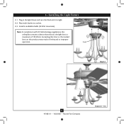
Plug in fire hazard or improper operation. Exceeding that restricts the light kit to a maximum of 190 Watts. Note: In compliance with US federal energy regulations, this ceiling fan contains a device that limit or the marked limit on a socket. 8-3. Finial Step 8-1 11 41968-01 • 10/02/08 • Hunter Fan Company Steps 8-2 - 8-3 Install 4 candelabra bulbs (40 Watt maximum). Place each shade on this product may result in the light fixture and turn the finial until it is tight. 8-2. 8 • Installing the Light Fixture 8-1.
Plug in fire hazard or improper operation. Exceeding that restricts the light kit to a maximum of 190 Watts. Note: In compliance with US federal energy regulations, this ceiling fan contains a device that limit or the marked limit on a socket. 8-3. Finial Step 8-1 11 41968-01 • 10/02/08 • Hunter Fan Company Steps 8-2 - 8-3 Install 4 candelabra bulbs (40 Watt maximum). Place each shade on this product may result in the light fixture and turn the finial until it is tight. 8-2. 8 • Installing the Light Fixture 8-1.
Owner's Manual
Page 12
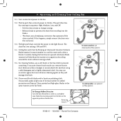
...in the same manner as they will distribute the warmer air trapped at the ceiling around the room without causing a draft. 9-5. Ceiling fans work best by blowing air downward (counterclockwise blade rotation) in warm weather to the ...fan pull chain controls power to the light fixture. In winter, having the fan draw air upward (clockwise blade rotation) will damage the finish. 9-6. Turn on the fan to cool the room with a furniture polishing cloth. 9 • Operating and Cleaning Your Ceiling Fan 9-1. Reversing Switch 12 41968-01 • 10/02/08 • Hunter Fan...
...in the same manner as they will distribute the warmer air trapped at the ceiling around the room without causing a draft. 9-5. Ceiling fans work best by blowing air downward (counterclockwise blade rotation) in warm weather to the ...fan pull chain controls power to the light fixture. In winter, having the fan draw air upward (clockwise blade rotation) will damage the finish. 9-6. Turn on the fan to cool the room with a furniture polishing cloth. 9 • Operating and Cleaning Your Ceiling Fan 9-1. Reversing Switch 12 41968-01 • 10/02/08 • Hunter Fan...
Parts Guide
Page 1
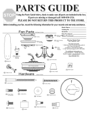
...additional information on: Hunter Products Trouble Shooting Dealer Location Service Center Locator Call 1-800-448-6837 www.hunterfan.com 49 Light Kit Assembly 44 Blade Iron Set Motor Housing Assembly Hardware (Drawn to Scale) 3 Canopy Model Name Catalog No. Before installing your fan, record the following... here Purchased 46 Blade Set 7 Hanger Ball / Downrod Assembly 4 Canopy Trim Ring 2 Ceiling Plate 29 Switch Housing Cover Missing / Broken Parts: Call 1-888-830-1326 267 Finial, Switch Housing Fan does not work: 1. PLEASE DO NOT RETURN THIS PRODUCT TO THE STORE. If parts are...
...additional information on: Hunter Products Trouble Shooting Dealer Location Service Center Locator Call 1-800-448-6837 www.hunterfan.com 49 Light Kit Assembly 44 Blade Iron Set Motor Housing Assembly Hardware (Drawn to Scale) 3 Canopy Model Name Catalog No. Before installing your fan, record the following... here Purchased 46 Blade Set 7 Hanger Ball / Downrod Assembly 4 Canopy Trim Ring 2 Ceiling Plate 29 Switch Housing Cover Missing / Broken Parts: Call 1-888-830-1326 267 Finial, Switch Housing Fan does not work: 1. PLEASE DO NOT RETURN THIS PRODUCT TO THE STORE. If parts are...


