

Installation Guide
Page 1
...lead wires extend from any hardware store or electrical supply house. 5-4. Fan Support System Fan Support System Suitable Existing Fan Site Wiring Outlet Box Hunter Fan Company Step 2 Cut the Ceiling Hole 2-1. Obtain a UL-approved octagonal 4" x 1-1/2" outlet box, plus two #8 x 1-1/2" wood...From Wall or Nearest Obstruction Step 1 Choose the Fan Site Proper ceiling fan location and attachment to your fan manual and begin with 2 • Installing the Ceiling Plate. Tools and Supplies You May Need • Drill • Keyhole saw • 2' x 4' support brace • UL-...
...lead wires extend from any hardware store or electrical supply house. 5-4. Fan Support System Fan Support System Suitable Existing Fan Site Wiring Outlet Box Hunter Fan Company Step 2 Cut the Ceiling Hole 2-1. Obtain a UL-approved octagonal 4" x 1-1/2" outlet box, plus two #8 x 1-1/2" wood...From Wall or Nearest Obstruction Step 1 Choose the Fan Site Proper ceiling fan location and attachment to your fan manual and begin with 2 • Installing the Ceiling Plate. Tools and Supplies You May Need • Drill • Keyhole saw • 2' x 4' support brace • UL-...

Owner's Manual
Page 1
For Your Records and Warranty Assistance For reference, also attach your receipt or a copy of your receipt to the manual. _W_e_s_t_si_d_e__II Model Name _2_1_6_2_1 Model No. Date Purchased Where Purchased Type 3 Models Owner's Guide and Installation Manual English Español Form# 42797-01 20081113 ©2008 Hunter Fan Co.
For Your Records and Warranty Assistance For reference, also attach your receipt or a copy of your receipt to the manual. _W_e_s_t_si_d_e__II Model Name _2_1_6_2_1 Model No. Date Purchased Where Purchased Type 3 Models Owner's Guide and Installation Manual English Español Form# 42797-01 20081113 ©2008 Hunter Fan Co.
Owner's Manual
Page 2
...To avoid possible electrical shock, before installing your fan, disconnect the power by turning off position, securely fasten a prominent warning device, such as a tag, to your records and warranty assistance, record information from the carton and Hunter nameplate label (located on the top... MANUAL CAREFULLY BEFORE BEGINNING INSTALLATION. If you cannot lock the circuit breakers in the world. Use only Hunter speed controls. © 2008 Hunter Fan Company 2 42797-01 • 11/13/08 • Hunter Fan Company SAVE THESE INSTRUCTIONS. • Use only Hunter replacement parts. •...
...To avoid possible electrical shock, before installing your fan, disconnect the power by turning off position, securely fasten a prominent warning device, such as a tag, to your records and warranty assistance, record information from the carton and Hunter nameplate label (located on the top... MANUAL CAREFULLY BEFORE BEGINNING INSTALLATION. If you cannot lock the circuit breakers in the world. Use only Hunter speed controls. © 2008 Hunter Fan Company 2 42797-01 • 11/13/08 • Hunter Fan Company SAVE THESE INSTRUCTIONS. • Use only Hunter replacement parts. •...

Owner's Manual
Page 3
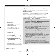
... instructions for ceilings less than 8 feet, you maximum installation flexibility and ease. Considering Optional Accessories Consider using Hunter's optional accessories, including a wall-mounted or remote speed control. Installer's Choice and Optional Accessories Support Brace Standard Mounting Style ... from the ceiling by a downrod (included). Understanding Mounting and Installer's Choice® Hunter's patented 3-position mounting system provides you can install your Hunter fan in . You can purchase Hunter extension downrods. diameter pipe to these instructions, and use the ...
... instructions for ceilings less than 8 feet, you maximum installation flexibility and ease. Considering Optional Accessories Consider using Hunter's optional accessories, including a wall-mounted or remote speed control. Installer's Choice and Optional Accessories Support Brace Standard Mounting Style ... from the ceiling by a downrod (included). Understanding Mounting and Installer's Choice® Hunter's patented 3-position mounting system provides you can install your Hunter fan in . You can purchase Hunter extension downrods. diameter pipe to these instructions, and use the ...
Owner's Manual
Page 4
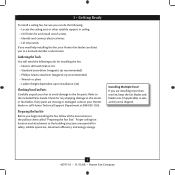
... recommended) • Wrench or pliers • Ladder (height dependent upon installation site) Checking Your Fan Parts Carefully unpack your Hunter dealer or call Hunter Technical Support Department at 888-830-1326. If you are installing more than one fan, keep the fan blades and blade irons (if ...applicable) in ceiling. • Drill holes for installing the fan: • Electric drill...
... recommended) • Wrench or pliers • Ladder (height dependent upon installation site) Checking Your Fan Parts Carefully unpack your Hunter dealer or call Hunter Technical Support Department at 888-830-1326. If you are installing more than one fan, keep the fan blades and blade irons (if ...applicable) in ceiling. • Drill holes for installing the fan: • Electric drill...

Owner's Manual
Page 5
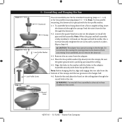
...have a diameter of 9/64 in the outlet box. Place a flat washer on the lower side. 5 42797-01 • 11/13/08 • Hunter Fan Company Tighten the screws into the 9/64 in the ceiling plate into the pilot holes you drilled. Wood Screw For Angled Ceilings: Be sure...plate are on each isolator into the wood support structure through the hole in . pilot holes; 2 • Installing the Ceiling Plate CAUTION: To avoid possible electrical shock, before installing your fan, disconnect the power by inserting the raised areas on the screws. Drill two pilot holes into the ...
...have a diameter of 9/64 in the outlet box. Place a flat washer on the lower side. 5 42797-01 • 11/13/08 • Hunter Fan Company Tighten the screws into the 9/64 in the ceiling plate into the pilot holes you drilled. Wood Screw For Angled Ceilings: Be sure...plate are on each isolator into the wood support structure through the hole in . pilot holes; 2 • Installing the Ceiling Plate CAUTION: To avoid possible electrical shock, before installing your fan, disconnect the power by inserting the raised areas on the screws. Drill two pilot holes into the ...

Owner's Manual
Page 6
Install three (3) assembly screws and tighten them securely. Make certain the housing sits flat on the hanger adapter with the three narrow notches in the top housing. Steps 3-1 - 3-2 Assembly Screw Top Housing Hanger Adapter 6 42797-01 • 11/13/08 • Hunter Fan Company To assemble the housing to the hanger adapter, align the three raised tabs on the adapter. 3-2. 3 • Assembling the Top Housing 3-1.
Install three (3) assembly screws and tighten them securely. Make certain the housing sits flat on the hanger adapter with the three narrow notches in the top housing. Steps 3-1 - 3-2 Assembly Screw Top Housing Hanger Adapter 6 42797-01 • 11/13/08 • Hunter Fan Company To assemble the housing to the hanger adapter, align the three raised tabs on the adapter. 3-2. 3 • Assembling the Top Housing 3-1.
Owner's Manual
Page 7
...; CAUTION: The adapter has a special coating on the ceiling plate through the canopy. Round Hole 7 42797-01 • 11/13/08 • Hunter Fan Company Once assembled, do not remove the downrod. 4-3. To assemble fan to hang down ) into the canopy. 4 • Assembling and Hanging ...(steps 4-1 - 4-2) or for low profile mounting (steps 4-3 - 4-5). Note: For low profile mounting, the downrod is fully installed, 2-3 threads on the adapter to Step 4-6. Skip to install the pipe and ball assembly. Place the low profile washer (lip down from the bottom of the canopy and the two...
...; CAUTION: The adapter has a special coating on the ceiling plate through the canopy. Round Hole 7 42797-01 • 11/13/08 • Hunter Fan Company Once assembled, do not remove the downrod. 4-3. To assemble fan to hang down ) into the canopy. 4 • Assembling and Hanging ...(steps 4-1 - 4-2) or for low profile mounting (steps 4-3 - 4-5). Note: For low profile mounting, the downrod is fully installed, 2-3 threads on the adapter to Step 4-6. Skip to install the pipe and ball assembly. Place the low profile washer (lip down from the bottom of the canopy and the two...

Owner's Manual
Page 8
... • 11/13/08 • Hunter Fan Company This device may cause undesired operation. The jumpers for each fan set to the transmitter. Change the position of the other fans. Make sure that may not cause harmful interference. 2. Install the included 12-volt battery into the ...transmitter. Changes or modifications not expressly approved by Hunter Fan Company could void your authority to have the receiver/transmitter for the transmitter are ...
... • 11/13/08 • Hunter Fan Company This device may cause undesired operation. The jumpers for each fan set to the transmitter. Change the position of the other fans. Make sure that may not cause harmful interference. 2. Install the included 12-volt battery into the ...transmitter. Changes or modifications not expressly approved by Hunter Fan Company could void your authority to have the receiver/transmitter for the transmitter are ...

Owner's Manual
Page 11
Align the holes in the canopy with the mounting holes on the ceiling plate. 7-3. Holding the canopy, raise the fan off the hook. 7-2. Canopy Mounting Screw 11 42797-01 • 11/13/08 • Hunter Fan Company Steps 7-1- 7-3 7 • Installing the Canopy 7-1. Insert and tighten the mounting screws securely.
Align the holes in the canopy with the mounting holes on the ceiling plate. 7-3. Holding the canopy, raise the fan off the hook. 7-2. Canopy Mounting Screw 11 42797-01 • 11/13/08 • Hunter Fan Company Steps 7-1- 7-3 7 • Installing the Canopy 7-1. Insert and tighten the mounting screws securely.

Owner's Manual
Page 13
...tighten all three screws. Install the remaining screw to secure the light kit fitter to the light kit fitter with two ballast screws. 9-7. Steps 9-1 - 9-8 Light Kit Fitter Fluorescent Bulb Globe Trim Band Step 9-9 Ballast Glass Globe 13 42797-01 • 11/13/08 • Hunter Fan Company Align the ...keyholes in the light kit fitter with the three holes in the narrow ends of the keyholes. 9-4. Install the included 22 Watt fluorescent bulb into the globe trim band. Attach the ballast to...
...tighten all three screws. Install the remaining screw to secure the light kit fitter to the light kit fitter with two ballast screws. 9-7. Steps 9-1 - 9-8 Light Kit Fitter Fluorescent Bulb Globe Trim Band Step 9-9 Ballast Glass Globe 13 42797-01 • 11/13/08 • Hunter Fan Company Align the ...keyholes in the light kit fitter with the three holes in the narrow ends of the keyholes. 9-4. Install the included 22 Watt fluorescent bulb into the globe trim band. Attach the ballast to...

Parts Guide
Page 1
... Kit Assembly Globe/Shade Light bulb / Bulb Globe Trim Ring Blade Set Hardware Kit Washer, Installers Choice Screw, #6-32X.500 Canopy Screw Screw, Low Profile Wood Screw Blade Assembly Screw Flat ...Mounting Isolator Balancing Kit Ballast Remote Control Receiver Remote Control Transmitter Remote Control Cradle Model # 21621 Asm. If parts are included in the box. Wood Screw Screw, Low Profile Canopy ...-50 99093-00-860 1 07570-01 1 87108-01 1 87075-01 1 85095-03 1 85093-01 Hunter Fan Company • 2500 Frisco Avenue • Memphis, TN 38114 • www.hunterfan.com •...
... Kit Assembly Globe/Shade Light bulb / Bulb Globe Trim Ring Blade Set Hardware Kit Washer, Installers Choice Screw, #6-32X.500 Canopy Screw Screw, Low Profile Wood Screw Blade Assembly Screw Flat ...Mounting Isolator Balancing Kit Ballast Remote Control Receiver Remote Control Transmitter Remote Control Cradle Model # 21621 Asm. If parts are included in the box. Wood Screw Screw, Low Profile Canopy ...-50 99093-00-860 1 07570-01 1 87108-01 1 87075-01 1 85095-03 1 85093-01 Hunter Fan Company • 2500 Frisco Avenue • Memphis, TN 38114 • www.hunterfan.com •...


