Installation Instructions
Page 1
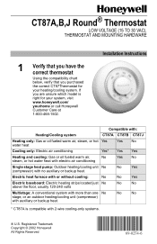
If you purchased the correct CT87Thermostat for your heating/cooling system. Registered Trademark Copyright © 2002 Honeywell All Rights Reserved 69-0274-6 CT87A,B,J Round® Thermostat LOW VOLTAGE (15 TO 30 VAC), THERMOSTAT AND MOUNTING HARDWARE 1 Verify that you have the correct thermostat Using the compatibility chart below, verify that you are unsure which model is compatible with...
If you purchased the correct CT87Thermostat for your heating/cooling system. Registered Trademark Copyright © 2002 Honeywell All Rights Reserved 69-0274-6 CT87A,B,J Round® Thermostat LOW VOLTAGE (15 TO 30 VAC), THERMOSTAT AND MOUNTING HARDWARE 1 Verify that you have the correct thermostat Using the compatibility chart below, verify that you are unsure which model is compatible with...
Installation Instructions
Page 2
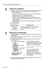
...; Hand or power drill with 1/16-in . You may affect its accuracy. CT87A,B,J ROUND® THERMOSTAT 2 Prepare for your type of MERCURY SWITCH IN A THERMOSTAT system when you reach Step 8 of M20206 this installation. 4. rough handling may need to the heating/cooling system at the main fuse/circuit breaker panel. 2. Necessary if installing on the wall; Locate...
...; Hand or power drill with 1/16-in . You may affect its accuracy. CT87A,B,J ROUND® THERMOSTAT 2 Prepare for your type of MERCURY SWITCH IN A THERMOSTAT system when you reach Step 8 of M20206 this installation. 4. rough handling may need to the heating/cooling system at the main fuse/circuit breaker panel. 2. Necessary if installing on the wall; Locate...
Installation Instructions
Page 4
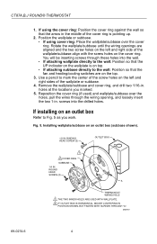
... cover ring, and drill two 1/16-in . screws into the wall. • If attaching wallplate directly to the wall: Position so that the fan and heating/cooling switches are aligned and the two screw holes on the left and right sides of the cover ring is on top. • If attaching...; If using the cover ring: Position the cover ring against the wall so that the arrow in the middle of the wallplate or subbase. 4. ROUND HEAD SCREW (2) A THERMOSTAT WIRING HOLE 1 THE TWO INNER HOLES ARE USED WITH WALLPLATE. 2 IF OUTLET BOX IS HORIZONTAL, MOUNT COVER RING IN POSITION SHOWN, BUT FASTEN WITH...
... cover ring, and drill two 1/16-in . screws into the wall. • If attaching wallplate directly to the wall: Position so that the fan and heating/cooling switches are aligned and the two screw holes on the left and right sides of the cover ring is on top. • If attaching...; If using the cover ring: Position the cover ring against the wall so that the arrow in the middle of the wallplate or subbase. 4. ROUND HEAD SCREW (2) A THERMOSTAT WIRING HOLE 1 THE TWO INNER HOLES ARE USED WITH WALLPLATE. 2 IF OUTLET BOX IS HORIZONTAL, MOUNT COVER RING IN POSITION SHOWN, BUT FASTEN WITH...

Installation Instructions
Page 5
... SPIRIT LEVEL LEVELING POSTS (2) OPENING FOR THERMOSTAT WIRING MOUNTING SLOTS M3319A 2. screws, through the wiring hole on the left side of the cover ring. 3. To level the subbase, use the leveling posts directly below the Heat and Fan indicators. screws. 4. Tighten ...the mounting screws after making sure that the arrow in the middle of the wallplate/subbase. 5 Level the wallplate or subbase IMPORTANT: The wallplate/subbase must be level to the cover ring with two 1/2-in Fig. 6. CT87A,B,J ROUND® THERMOSTAT...
... SPIRIT LEVEL LEVELING POSTS (2) OPENING FOR THERMOSTAT WIRING MOUNTING SLOTS M3319A 2. screws, through the wiring hole on the left side of the cover ring. 3. To level the subbase, use the leveling posts directly below the Heat and Fan indicators. screws. 4. Tighten ...the mounting screws after making sure that the arrow in the middle of the wallplate/subbase. 5 Level the wallplate or subbase IMPORTANT: The wallplate/subbase must be level to the cover ring with two 1/2-in Fig. 6. CT87A,B,J ROUND® THERMOSTAT...

Installation Instructions
Page 7
CT87A WALLPLATE R Y W POWER HEAT TO SYSTEM M20183 Fig. 9. R Y W CT87A WALLPLATE WIRE LABELS (LETTERS ON ORIGINAL THERMOSTAT TERMINALS) R 3-WIRE W HOT WATER ZONE VALVE B M20184 Fig. 10. CT87A for a 4-wire heating/cooling system. COOL • OFF • HEAT FAN ON RH G RC Y W AUTO • CT87B SUBBASE POWER FAN COOL TO SYSTEM HEAT JUMPER RH TO RC M20185 7 69-0274-6 CT87B for a 2-wire heating only system. CT87A for a 3-wire hot water heating only system. CT87A,B,J ROUND® THERMOSTAT Fig. 8.
CT87A WALLPLATE R Y W POWER HEAT TO SYSTEM M20183 Fig. 9. R Y W CT87A WALLPLATE WIRE LABELS (LETTERS ON ORIGINAL THERMOSTAT TERMINALS) R 3-WIRE W HOT WATER ZONE VALVE B M20184 Fig. 10. CT87A for a 4-wire heating/cooling system. COOL • OFF • HEAT FAN ON RH G RC Y W AUTO • CT87B SUBBASE POWER FAN COOL TO SYSTEM HEAT JUMPER RH TO RC M20185 7 69-0274-6 CT87B for a 2-wire heating only system. CT87A for a 3-wire hot water heating only system. CT87A,B,J ROUND® THERMOSTAT Fig. 8.

Installation Instructions
Page 8
CT87B for 4-wire single stage heat pump. CT87J for a 5-wire heating/cooling system. CT87A,B,J ROUND® THERMOSTAT Fig. 11. COOL • OFF • HEAT FAN ON RH G RC Y W AUTO • CT87B SUBBASE HEATING POWER FAN TO SYSTEM COOLING POWER TO SYSTEM COOL HEAT Fig. 12. M20228 69-0274-6 8 M20225 COOL • OFF • HEAT FAN ON WG Y P R B O JUMPER W TO Y AUTO • CT87J...
CT87B for 4-wire single stage heat pump. CT87J for a 5-wire heating/cooling system. CT87A,B,J ROUND® THERMOSTAT Fig. 11. COOL • OFF • HEAT FAN ON RH G RC Y W AUTO • CT87B SUBBASE HEATING POWER FAN TO SYSTEM COOLING POWER TO SYSTEM COOL HEAT Fig. 12. M20228 69-0274-6 8 M20225 COOL • OFF • HEAT FAN ON WG Y P R B O JUMPER W TO Y AUTO • CT87J...

Installation Instructions
Page 9
...15 SCALE .12 .10 M20226 3. CT87A,B,J ROUND® THERMOSTAT 7 Mount the thermostat 1. Fig. 15. Fig. 14. Tightening mounting screws. Adjusting heat anticipator indicator. NOTE: These screws complete the installation of the thermostat. Pull off the thermostat cover and discard the red plastic insert that the... Fig. 15. CAPTIVE SCREWS (3) M20227 9 69-0274-6 Place the thermostat over the wallplate or subbase so that holds the mercury switch in Fig. 14. Using a pencil point, slide the heat anticipator indicator to 1.2 on the wallplate/subbase. 4. Tighten the three ...
...15 SCALE .12 .10 M20226 3. CT87A,B,J ROUND® THERMOSTAT 7 Mount the thermostat 1. Fig. 15. Fig. 14. Tightening mounting screws. Adjusting heat anticipator indicator. NOTE: These screws complete the installation of the thermostat. Pull off the thermostat cover and discard the red plastic insert that the... Fig. 15. CAPTIVE SCREWS (3) M20227 9 69-0274-6 Place the thermostat over the wallplate or subbase so that holds the mercury switch in Fig. 14. Using a pencil point, slide the heat anticipator indicator to 1.2 on the wallplate/subbase. 4. Tighten the three ...

Installation Instructions
Page 10
... furnace stays on the thermometer. The heating system should stop. Turn the dial until the temperature on the setting scale is reached, move the heat anticipator pointer to Heat. 3. Snap on the thermometer. If you recorded in the table below. CT87A,B,J ROUND® THERMOSTAT 8 Set the heat anticipator for your type of system shown in Step 3, sub-step...
... furnace stays on the thermometer. The heating system should stop. Turn the dial until the temperature on the setting scale is reached, move the heat anticipator pointer to Heat. 3. Snap on the thermometer. If you recorded in the table below. CT87A,B,J ROUND® THERMOSTAT 8 Set the heat anticipator for your type of system shown in Step 3, sub-step...

Installation Instructions
Page 11
CT87A,B,J ROUND® THERMOSTAT Check cooling IMPORTANT: To avoid damaging the compressor in the air conditioner, do not operate the cooling system when the outdoor temperature is tested, wait five minutes before switching to Cool. IMPORTANT: After heating is below room temperature. CT87B, J switches Switch System Fan Setting Result Cool Off The thermostat controls your heating system. Operation To...
CT87A,B,J ROUND® THERMOSTAT Check cooling IMPORTANT: To avoid damaging the compressor in the air conditioner, do not operate the cooling system when the outdoor temperature is tested, wait five minutes before switching to Cool. IMPORTANT: After heating is below room temperature. CT87B, J switches Switch System Fan Setting Result Cool Off The thermostat controls your heating system. Operation To...


